TMI HORNET 5600 User manual

TMI HORNET
BACKHOE
OPERATION & INSTALLATION MANUAL BACKHOE
Hornet 5600,6600,7600 & 8600 Backhoes

2
TABLE OF CONTENTS
SECTION PAGE SECTION PAGE
Safety ....................................2 Removal/Storage .....................16
Safety Decals …........................3 Hydraulic Trouble Shooting .......18
Federal Laws and Regulations ....6 Valve Repair ............................21
General Operation ....................7 Control Valves ……………………….23
Controls ..................................8 Assembly ................................25
Operating The Backhoe .............9 Hydraulic Hook-Up ...................26
Placing The Stabilizers ..............9 and 11 Mounting Kits ...........................28
Transporting The Backhoe ........11 Bucket Spec ………………………………..37
Filling The Bucket ....................12
Torque Values …………………………………....38
Backfilling ..............................13 Service Notes …………………….……….…39
Service ..................................14
Parts ……………………………………………….41/49
Beginning Of The Season .........14
Hydraulic System .....…............14
Lubrication ............................15 Warranty………………………………………. 50 & 51
UNDERSTAND SIGNAL WORDS
DANGER: Indicates an imminently
hazardous situation which, if not
avoided, will result in death or serious
injury. This signal word is to be
limited to the most extreme situations.
WARNING: Indicates a potentially
hazardous situation which, if not
avoided, could result in death or
serious injury.
CAUTION: Indicates a potentially
hazardous situation which, if not avoided,
may result in minor or moderate injury. It
may also be used to alert against unsafe
practices.
IMPORTANT SAFETY PRECAUTIONS
This
symbol
is
used
to
call
attention
to
safety
precautions
that
should
be
followed by
the
operator
to
avoid
accidents.
W
hen
you
see
this
symbol,
carefully
read
the
message
that
follows
and
heed
its
advice.
Failure
to
comply
with
safety
precautions
could
result
in
serious
bodily
injury.
In addition to the design and configuration of equipment, hazard control and accident prevention are
dependent upon the awareness, concern, prudence, and proper training of personnel in the operation,
transport, maintenance and storage of equipment. Lack of attention to safety can result in accident,
personal injury, reduction of efficiency and worst of all-loss of life. Watch for safety hazards and correct
deficiencies promptly. Use the following safety precautions as a general guide to safe operations
when using this machine. Additional safety precautions are used throughout this manual for specific
operating and maintenance procedures. Read this manual and review the safety precautions often
until you know the limitations.
AVOID HIGH-PRESSURE FLUID
ESCAPING fluid under pressure can have sufficient force to penetrate the skin and cause serious injury. Be
sure to stop engine and relieve all pressure before disconnecting lines. Be sure all connections are tight and
that lines, pipes, and hoses are not damaged before applying pressure to the system. Fluid escaping not
your hands-to search for suspected leaks. SEE A DOCTOR at once if injured by escaping fluid. Serious
infection or gangrene can develop if proper medical treatment is not administered immediately.

3
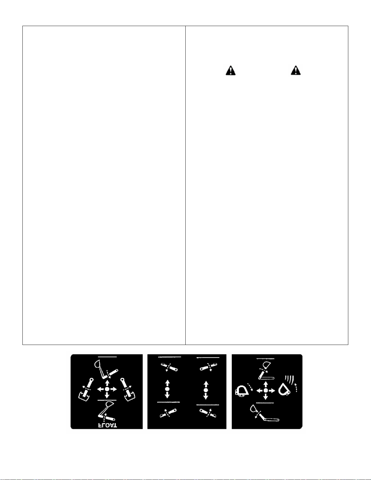
SAFETY DECALS
The safety of the operator was a prime consideration in the design of the backhoe. Proper shielding,
convenient controls, simple adjustment and other safety features have been built into this implement. The
following decals are located on the backhoe. Keep decals clean and replace them immediately if they are
missing. Contact your dealer or The Tractor Man Inc for replacements.
Location: Left Side of Control Tower Location: Left Side Toe Shield Area Location: Right Side of Control Tower
Location: Right Side of Control Tower

4
SAFETY PRECAUTIONS CONTINUED
THE TRACTOR AND/OR LOADER (IF EQUIPPED)
1. Read the tractor and/or loader operator's manual to learn how to operate your tractor and/or loader
safely. Failure to do so could result in serious injury or death and equipment damage.
2. It is recommended that tractor be equipped with Rollover Protective System (ROPS) and a seat belt be
used for all loader operations
3. Add wheel ballast or front weight for stability.
4. Move wheels to the tractor manufacture's widest recommended settings to increase stability.
5. For better stability, use tractor with wide front axle rather than tricycle front wheels.
6. Move and turn the tractor at low speeds.
7. Stop tractor engine, place transmission in park (or neutral), engage parking break, lower loader arms
to ground, cycle all hydraulic controls to relieve pressure, allow machine moving parts to stop, remove
ignition key to prevent unauthorized person from starting engine before dismounting tractor or
serving, repairing, or making adjustments to the equipment.
8. Wear personal protective equipment (PPE), such as, but not limited to, protection for eyes, ears, lungs,
head. hands and feet when operating, servicing, or repairing equipment. Avoid wearing loose clothing
or jewelry that may catch and entangle on equipment moving parts.
THE BACKHOE
1.
DO
NOT
operate the backhoe unless it is rigidly attached to the tractor.
2.
KNOW
your controls. Read this operator's manual and the manual provided with your tractor. Learn how to stop
the tractor, the engine and the backhoe quickly in an emergency.
3.
PROVIDE
adequate front end weight to counter-balance the backhoe at all times. 20% of the total tractor, loader
and backhoe weight must be on the tractor front axle. If unsure of weight distribution, at a weight scale. Total
vehicle weight, including backhoe and counter weights, must not exceed the ROPS certificate for gross vehicle
weight.
4.
BE
SURE
the area is clear of overhead or underground utilities or other hazards.
5.
POSITION
a barricade around the work area.
6.
KEEP
all bystanders a safe distance away.
7.
DO
NOT
attempt to enter operator's platform backhoe by using the stabilizers as a step.
8.
OPERATE
from the backhoe operator's seat only.
9.
ALLOW
only one person to operate the backhoe at any time.
10.
DISENGAGE
safety locks as shown in Figure 1&3 before attempting to operate the backhoe.
11.
NEVER
dig with the backhoe unless the stabilizers are properly set.
12.
DO
NOT
dig under stabilizers or tractor backhoe. Soft ground or sandy soil can cause cave-ins.
13.
KEEP
BUCKET
away from the stabilizer area to avoid possible stabilizer damage.

5
14.
ALWAYS
swing bucket uphill to dump when on a hillside and keep loaded bucket low.
15.
SET
BRAKES
and block wheels when operating on hills and banks to avoid dangerous runaway.
16.
WATCH
for overhead wires. DO NOT touch wires with any part of the backhoe.
17.
NEVER
allow a person to work under a raised bucket.
18.
NEVER
lift a person with the backhoe.
19.
DO
NOT
use the backhoe as a battering ram. Use the backhoe only for digging.
20.
ALWAYS
lower the backhoe bucket and stabilizers to the ground, shut off engine, and apply the parking
break before getting off unit, or when not digging.
21.
NEVER
leave the tractor unattended with the engine running.
22.
DO
NOT
attempt to raise the tractor off the ground or move the tractor forward or backward using the backhoe
Dipper stick or bucket.
TRANSPORTATION
1.
ALWAYS
engage safety locks before transporting backhoe. See Figure 1 & 3.
2.
DO
NOT
drive the tractor near the edge of a ditch or excavation.
3.
ALWAYS
use accessory lights and devices when transporting on a road or highway to warn operators of other
vehicles. Check your local government regulations.
4.
BE
SURE
the SMV emblem is visible to the rear.
ADJUSTMENTS AND INSPECTION
1.
CHECK
pins that attach backhoe to tractor and all pivot pins for tightness several times daily. Replace
any parts that are bent, broken or missing.
2.
ALWAYS
engage safety locks before servicing backhoe. See Figures 1 & 3.
3.
DO
NOT
oil, grease, or adjust the backhoe while it is in motion. For greasing, see Service section for details.
4.
DO
NO
T change any backhoe relief valve settings. They are factory set for best backhoe performance and safety.
5.
PROTECT
YOUR EYES
- WEAR SAFETY GLASSES.
6.
GUARD
AGAINST
INJURY
when driving connecting pins or performing any repair in which particles can
chip from work piece or striking tool.
7.
DO
NOT
remove any guards on backhoe or tractor.

6
IMPORTANT FEDERAL LAWS AND REGULATIONS*
CONCERNING EMPLOYERS, EMPLOYEES AND OPERATIONS.
*(This section is intended to explain in board terms the concept and effect of the following federal laws and
regulations. It is not intended as a legal interpretation of the laws and should not be considered as such).
U.S. Public Laws 91-596 (The Williams-Steiger Occupational and Health Act of 1970) OSHA
This Act Seeks.
"...to assure so far as possible every working man and woman in the nation safe and healthful working
conditions and to preserve our human resources..."
DUTIES
Sec. 5 (a) Each employer-
(1) Shall furnish to each of his employees employment and place of employment which are free from
recognized hazard that are causing or are likely to cause death or serious physical harm to his employees;
(2) Shall comply with occupational safety and health standard promulgated under this Act.
(b) Each employee shall comply with occupational safety and health standards and all rules, regulations
and orders issued pursuant to this Act which are applicable to his own actions and conduct.
OSHA Regulations
Current OSHA regulations state in part: "At the time of initial assignment and at least annually thereafter,
the employer shall instruct every employee in the safe operation and servicing of all equipment with which
the employee is, or will
be involved." These will include (but are not limited to) instructions to: Keep all guards in place when the machine is
in operation;Permit no riders on equipment;
Stop engine, disconnect the power source, and wait for all machine movement to stop before servicing, adjusting,
cleaning or unclogging the equipment, except where the machine must be running to be properly serviced or
maintained, in which case the employer shall instruct employees as to all steps and procedures which are necessary
to safely service or maintain the equipment.
Make sure everyone is clear of machinery before starting the engine, engaging power, or operating the machine.
EMPLOYEE TRACTOR OPERATING INSTRUCTIONS:
1. Securely fasten your seat belt if the tractor has ROPS. 6. Do not permit others to ride.
2. Where possible, avoid operating the tractor near ditch,
embankments, and holes.
7. Operate the tractor smoothly - no jerky turns, starts, or
stops.
3. Reduce speed when turning, crossing slopes, and on
rough, slick, or muddy surfaces.
8. Hitch only to the drawbar and hitch points
recommended by tractor manufactures.
4. Stay off slopes too steep for safe operation. 9. When the tractor is stopped, set brakes securely and
use park lock if available.
5. Watch where you are going, especially at row
ends, on roads, and around trees.
Child
Labor
Under
16
Years
Old
Some regulations specify that no one under the age of 16 may operate power machinery. It is your responsibility to
know what these regulations are in your own area or situation. (Refer to U.S. Dept. of Labor, Employment Standard
Administration, Wage & Home Division, Child Labor Bulletin #102.)
7
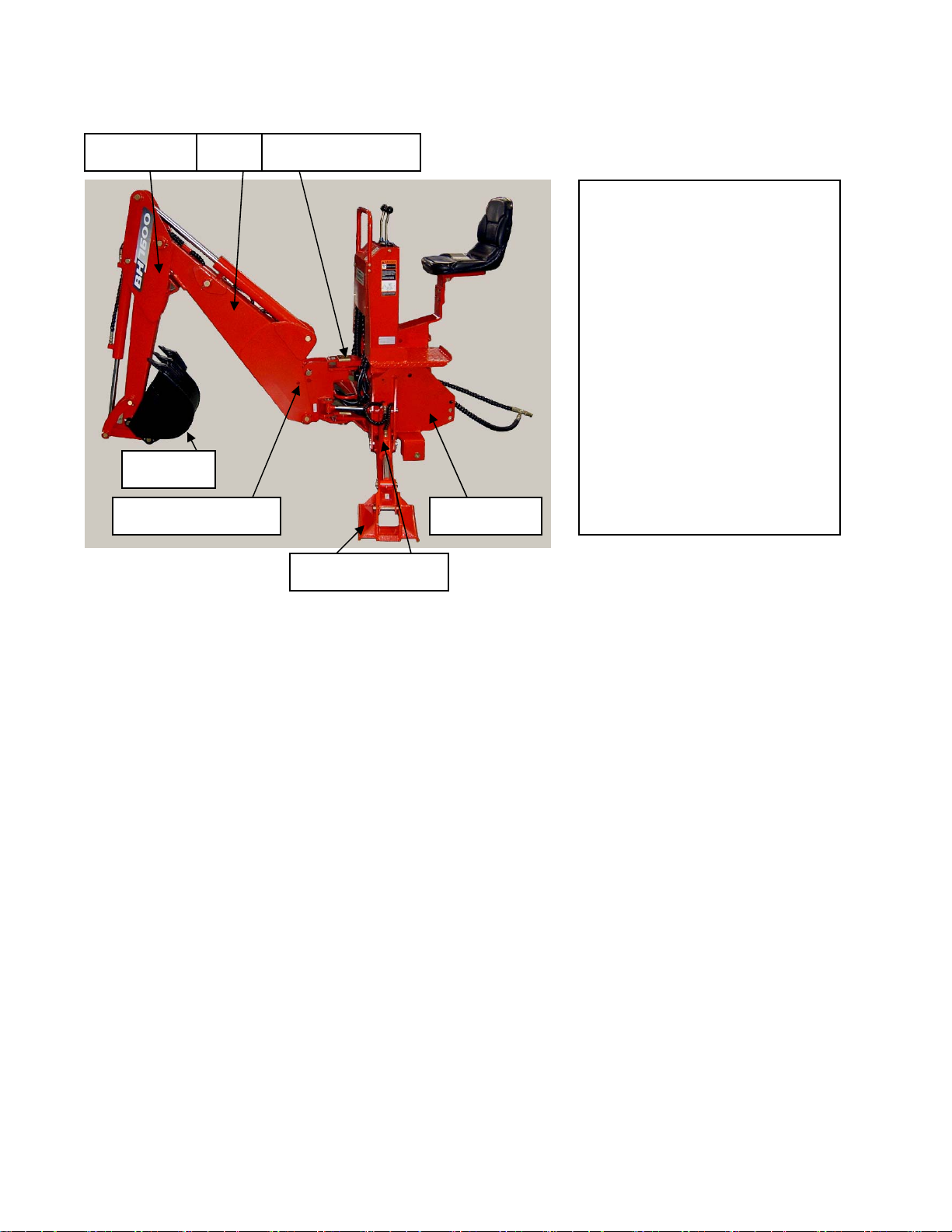
GENERAL OPERATION
Dipper Stick Boom Safety Swing Lock
Boom Safety Lock Main Frame
Stabilizer Cylinder
Bucket
CAUTION
To avoid possible injury,
observe the following safety
rules BEFORE OPERATING the
backhoe:
1. BE SURE the area is clear of
underground utilities or other
hazards
2. POSITION a barricade
around the work area.
3. PROVIDE adequate front
end weight to counter-balance
the tractor at all times.
20% of the total tractor.
8
DIRECTIONS: The terms right, left, front and back
shall be determined from the position of the operator
when seated in the operating position on the backhoe.
ENGINE SPEED
The speed at which the backhoe operates is part-
ially dependent on engine RPM. Use a moderate
engine speed to start and increase it as your
experience permits. Refer to "DIMENSIONS AND
SPECIFICATONS" on Page 42 for hydraulic flow volume
requirement. When powering from tractor systems with
higher output, reduce engine RPM to obtain acceptable
backhoe operating speed.
Figure 2
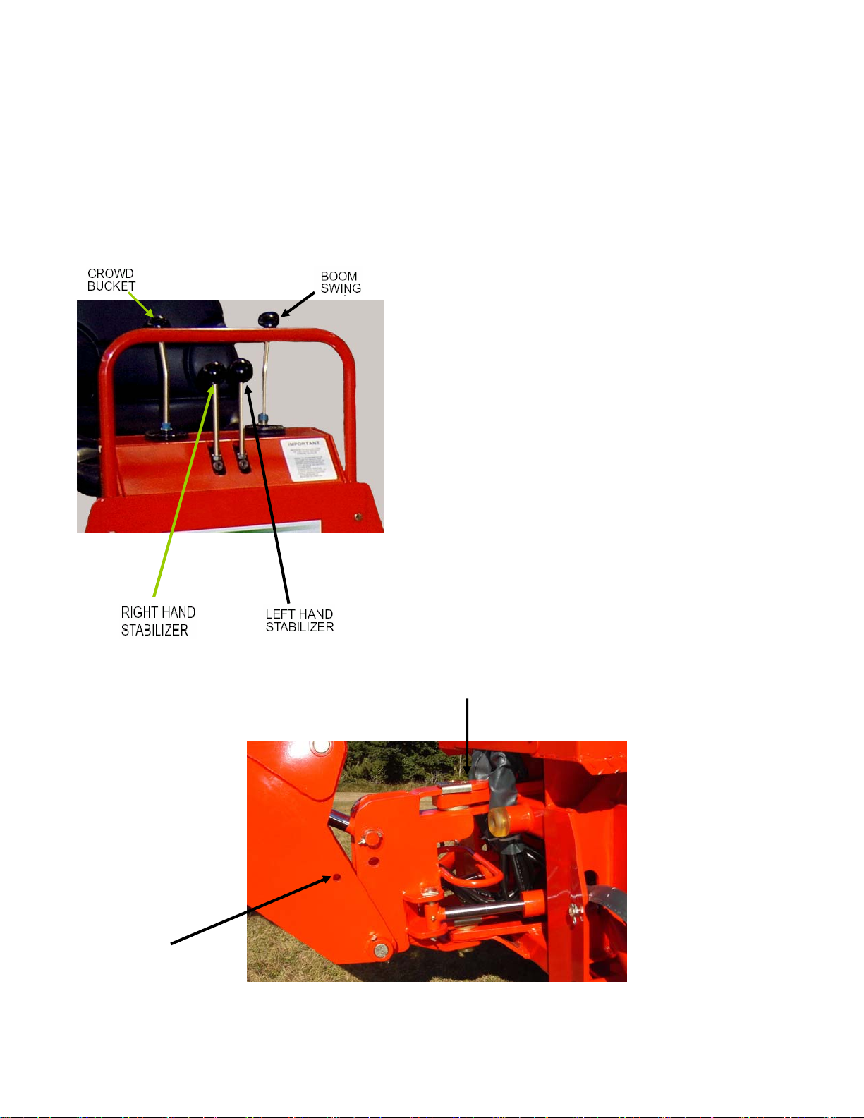
CONTROLS
The backhoe has two major control levers plus the
stabilizer control levers. These controls are located
on the control panel directly ahead of the operator.
See Figure2. The following is a list of the controls,
with the function of each, reading from left to right.
1. Boom/Swing: Push lever forward, the boom
moves down, away from the operator. Pull lever back,
the boom moves up, toward the operator.
The Boom/Swing Control lever has an added "float"
function. A detent or stop should be felt when the
lever is pushed forward to move the boom down.
Pushing the lever forward more will overcome the
detent and cause the boom to float, or move down
or up freely, depending on the forces acting on it.
when the lever is released it should return to the
center, neutral position.
Move lever to the left, the backhoe swings to the left.
Move lever to the right, the backhoe swings to the right.
By moving the lever to one of the intermediate positions,
the boom can be swung left or right at the same it is
being raised or lowered, performing the two operations
simultaneously.
SWING LEFT AND LOWER the boom by moving the
control lever forward and to the left.
SWING LEFT AND RAISE the boom by moving the
control lever back and to the left.
Safety Swing Lock Pin
Boom Safety Lock Pin
Goes Here
9
1. SWING RIGHT AND LOWER the boom by moving
the lever forward and to the right.
2. SWING RIGHT AND RAISE the boom by moving the
lever forward to the right.
3. Left Hand Stabilizer: Push lever downward, the LH
stabilizer lowers. Pull lever upward, the LH stabilizer
raises.
4. Right Hand Stabilizer: Push lever downward, the
RH stabilizer lowers. Pull lever upward, the RH
stabilizer raises.
5. Crowed/Bucket: Push lever forward, the dipper
stick moves out, away from the operator. Pull lever
back, the dipper stick moves in, toward the operator.
Move lever to left, the bucket curls in. Move lever to
right, the bucket extends out.
By moving the lever to one of the intermediate positions,
the dipper stick can be extended or retracted at the same
time the bucket is being loaded or dumped.
EXTEND AND LOAD the bucket by moving the lever
forward and to the left.
RETRACT AND LOAD the bucket by moving the
lever back and to the left.
EXTEND AND DUMP the bucket by moving the lever
forward and to the right.
RETRACT AND DUMP the bucket by moving the
lever back and to the right.
The two operations of the room lever, combined
with the two operations performed by the bucket
and dipper stick control lever, provide four simultaneous
operations from the two levers, keeping cycle time to a
minimum.
In general, the direction of movement of a control
lever corresponds to the movement of the operating
member.
Operating the Backhoe
CAUTION
To avoid possible injury, observe the following
safety rules WHEN OPERATING the backhoe.
1. DISENGAGE safety locks as shown in Figure 3
before attempting to operate the backhoe. Store
lock pins in holes provided in operator platform.
2. OPERATE from the backhoe operator's seat only.
3. LOWER the stabilizers until the rear of the tractor
is totally supported by them. NOTE: Rear tires
should not come up off of the ground.
See diagram on Page 11.
4. DO NOT dig near the stabilizers.
5. DO NOT touch overhead wires with any part of
the backhoe.
6. DO NOT attempt to raise the tractor off the
ground or move the tractor forward or backward
using the backhoe dipper stick or bucket.
7. DO NOT lose stability by swinging the bucket
Down hill when positioned on a slope.
8. DO NOT lower the backhoe boom using the
"float" function (if equipped). It will freefall, and
could result in injury to bystanders or damage to
the backhoe.

10
It is not difficult to become an efficient operator.
Control lever operating decal is located on back of
the control panel. Study this decal. It will assist you
in becoming familiar with the controls.
Smooth, light handling of the controls will result in
the most efficient backhoe operation.
Operate the backhoe control levers to become
familiar with their speed and movements. The
engine speed and the size of the hydraulic system
will determine the speed of cylinder operation.
When powering from tractor systems with higher
output than required, reduce engine RPM to obtain
acceptable backhoe operating speed.
Swing the boom several times to practice controlling
the speed of swing. Do not operate the swing more
than 45 each way for the first few times, then
gradually increase the arc.
IMPORTANT: To avoid damage to the backhoe, do
not slam swing unit into the rubber bumpers.
The boom "float" function (if equipped) may be
used during digging to eliminate down pressure
whencleaning the bottom of a trench. The primary
purpose of the boom "float" function is to protect
the operator from serious injury in the event that
the backhoe or tractor hitch would fail.
Best results are obtained by digging near the center
of the swing arc so material can be dumped on
either side.
Best results are obtained by digging near the center
of the swing arc so material can be dumped on
either side.
As the operator becomes more familiar with the
operation of the backhoe, it will be common practice
to operate two controls at one time. For ex example,
with the bucket extended and the dipper stick
extended, the lift control and crowd control can be
operated together to bring the bucket toward the
operator with down pressure on it. As the dipper
stick approaches the operator, the crowd and
bucket controls can be operated to close the bucket
and trap the material. At the end of the stroke, the
lift and crowd controls are operated to move the
load up and away from the operator to save time
in clearing the excavation.
This dual operation of controls will speed and
simplify the digging operation. Normally the two or
more movements will not be equal or even
simultaneous, but as the pressure within the
cylinders changes, and the resistance on an
operating member of the hoe lessens, it will begin to
move. It is
balancing the force of one member against the
other.
NOTE: Actuating the bucket is the key to powerful
digging. Operating the crowd and bucket controls
simultaneously will insure a full bucket and prevent
waste motion and time.
Transporting the Backhoe:
IMPORTANT: To prevent serious damage to the
tractor, read and follow the instructions on the
following decal:
Location: Right Side of Boom

11
Set the stabilizers to remove weight from the rear wheels. The wheels are to remain touching the
ground as this provides for the widest stabilizer stance and the lowest center of gravity. Raising
the wheels off the ground will not only reduce stability and digging depth, but will perform and
impose unnecessary stress
12
General Operations
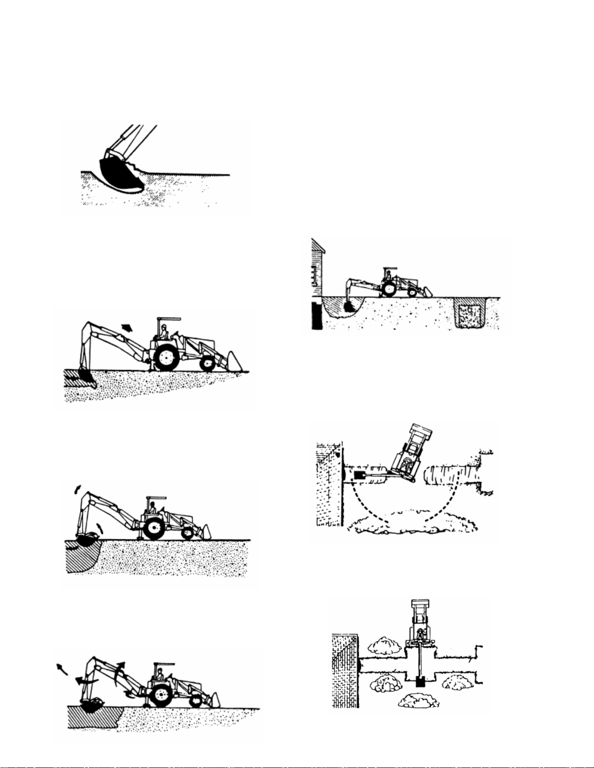
FILLING THE BUCKET
Control the bucket attitude throughout the digging
cycle to keep teeth at the proper angle for best
penetration. This will minimize dragging and
scraping through the ground.
When digging in hard-packed soil, bucket
penetration can be increased by applying down
pressure with the boom while crowding in and
curling the bucket. If the crowed action "stalls" it
may be necessary to apply lift occasionally during
the digging cycle to correct the bucket depth.
To obtain a cleaner trench and avoid the buildup of
material directly in front of the backhoe, crowed
out and completely curl the bucket while starting
to lift it from the excavation. In this way, excess
material will fall back into the excavation.
DUMPING THE BUCKET
To dump the bucket at the end of the digging
cycle, lift the bucket clear of the trench while
crowding it out and swinging it to the spoil pile.
As the pile is approached, dump the bucket. When
the bucket is empty, the dipper stick and bucket
are in position to resume digging upon return to
the trench.
IMPORTANT: Avoid constant jarring or hammering
type contact between the spoil pile and the loaded
bucket, as this may cause premature wear to the
backhoe pins and bushings.
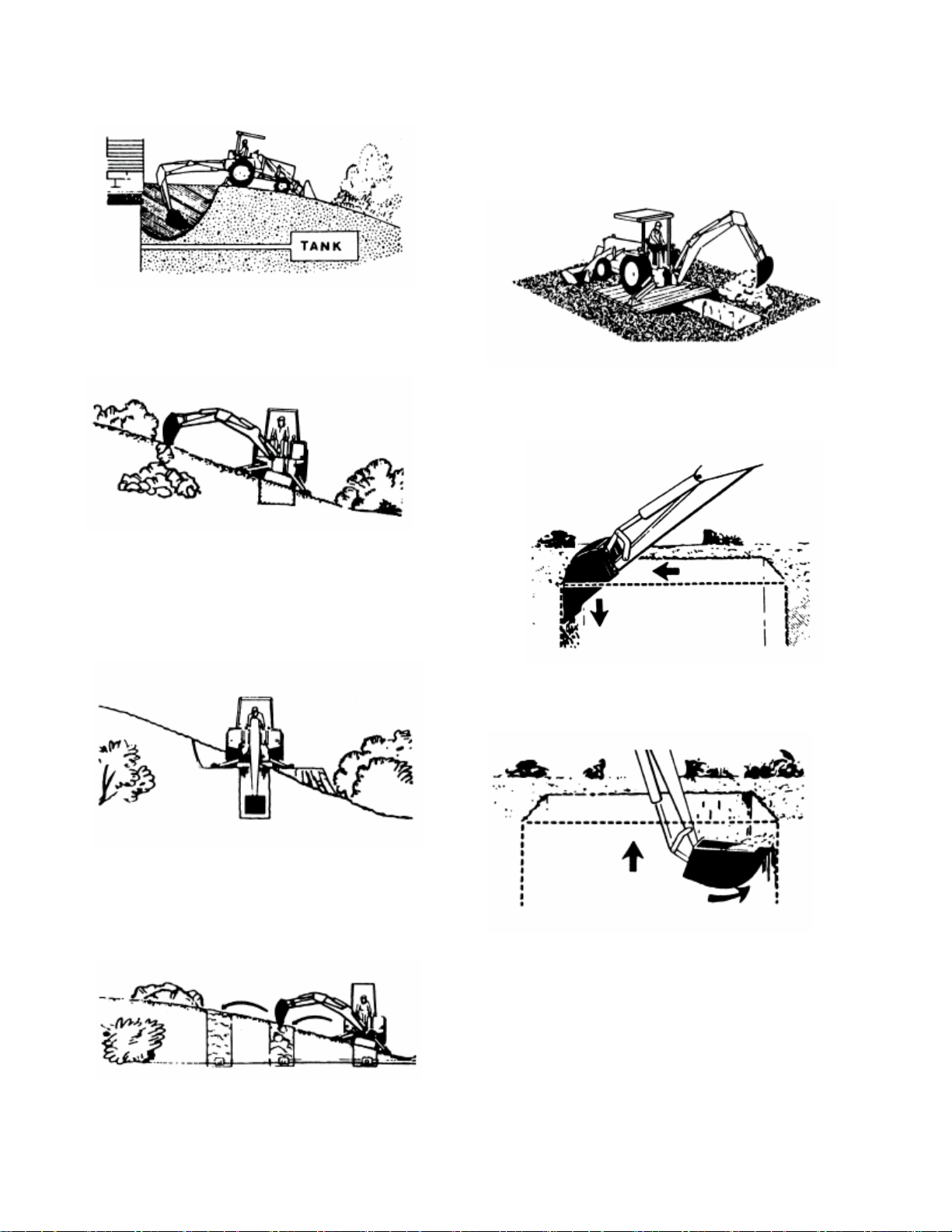
TRENCHING BETWEEN A BUILDING AND
OPEN EXCAVATIONS
Start the trench at the building. Trench out
halfway to the excavation. Then start trenching
from the excavation to the first trench. Dig toward
the first trench until there is just enough room to
move the unit out between the two trenches.
Position the unit so the backhoe swing post is over
the centerline of the trench connection. Dig with
the backhoe at extreme swing positions, and in as
close to the stabilizers as possible. Pile the spoil
on the opposite side of the trenches.
Position the unit forward with the lift and crowed
levers so the two trenches can be connected. Pile
the spoil on the opposite side of the trench.
13
General Operations
SIDE SLOPE EXCAVATING OR TRENCHING
Dig with backhoe uphill whenever possible.
Level the backhoe on slops with the stabilizers to
dig plumb trenches, or use the backhoe or loader
to cut a level slot for the uphill wheel and stabilizer.
Pile the spoil from the slot on the low side.
When on the side of a steep slope, cut a level
surface along the uphill side of the trench with the
loader.
Pile the spoil of the cut downhill. When digging,
pile the spoil of the trench uphill.
Dig field trenched progressively. As soon as one
trench is completed, have the workmen lay the tile.
Start the next trench, using the spoil to fill the
previous trench.
MISCELLANEOUS
When finishing straight walls or bell holes in sandy
soil, use a platform under the rear tires and
stabilizers. The platform distributes the load over a
larger area and lessons the possibility of a cave-in.
The platform also tends to keep the unit from
creeping rearward if hard digging is encountered.
FINISHING STRAIGHT WALLS
Finish the far wall by crowding out while forcing the
bucket down from the boom. Actuate the bucket
(curl out) to keep the bottom of the bucket vertical.
To finish the near wall, lift up and crowd in. Keep
the edges of the bucket horizontal.
BACKFILLING
Backfill by lifting the bucket over the spoil pile and
then crowding in. Pull both the crowd and lift levers
for smooth, even backfilling.
IMPORTANT: Do not backfill by using the swing
circuit and dragging the bucket sideways. Doing so
can cause damage to the dipper stick boom
swing cylinders or mainframe.

14
Service
CAUTION
To avoid possible injury, observe the following safety rules WHEN SERVICING the backhoe.
1. ENGAGE safety locks as shown in figure 1 & 3 before servicing the backhoe.
2. DO NOT oil, grease or adjust the backhoe while it is in motion.
3. DO NOT change any backhoe relief valve setting. They are factory set for best performance and safety.
4. ESCAPING FLUID under pressure can have sufficient force to penetrate the skin and cause serious
injury. Be sure to relieve all pressure before disconnecting lines. Be sure all connections are tight and that
lines, pipes and hoses are not damaged before applying pressure to the system.
5. FLUID ESCAPING from a very small hole can be almost invisible. Use a small piece of cardboard or
wood not your hands - to search for suspected leaks.
6. SEE A DOCTOR AT ONCE if injured by escaping fluid. Serious infection or gangrene can develop if
proper medical treatment is not administered immediately.
7. PROTECT YOUR EYES - Wear safety glasses. Guard against injury when driving connecting pins or
performing any repair in which particles can chip from work piece or striking tool.
BEGINNING OF SEASON
Remove all protective covering.
On the PTO pump contained system, maintain the reservoir oil at the proper level by looking at the oil
gauge. When checking oil level, the backhoe should be extended to full reach with the bucket rolled back
and resting on the ground. All cylinders are retracted except for the boom cylinder. Do not overfill: oil may
be forced out of the breather cap.
Change PTO Reservoir Hydraulic Oil and Filter every 200hrs, or earlier if neccessary.
Fill Reservoir with: SAE 10W40 engine oil with API “SF/SG” classification in northern climates. AW32
Fill Reservoir with: SAE 40W engine oil with API “SF/SG” classification in southern climates or AW42
Or Reservoir oil should be a all purpose tractor hydraulic oil, or AW32/AW42 is another good choice.
Check hydraulic hoses for deterioration and replace, if necessary.
Lubricate all grease fitting and oil handle linkage. Check hydraulic system for loss of fluid and, if
necessary, fill to proper level, or replace it if contaminated. Tighten all loose bolts, nuts and set screw.
Inspect bucket teeth and, if necessary, sharpen or replace them.
Operate the backhoe slowly for a short time before full time operation, to get used to the controls, and also
checking for hydraulic leaks, before placing the unit under full load.
Bleeding Backhoe Hydraulic System
If the hydraulic hoses have been disconnected from the backhoe or tractor, all trapped air must be
15
removed after the hoses are connected. Start tractor engine and operate backhoe through all movements
fully, several times, to purge the system of air.
Hydraulic System Hoses
Oil leaks in the pressure side of the system can be located by carefully inspecting the external area of
the hoses and fittings.
Check the return side of the system for leaks by examining the oil in the reservoir. If air is being
drawn into the system, the oil will contain air bubbles and appear to foam.
When tightening connections, always use two correct size wrenches.
IMPORTANT: Do not over-tighten fittings. Make them just tight enough to eliminate leaks.
NEVER use teflon tape on pipe thread fittings. Always use a paste type sealer.
Hoses on any backhoe are very severely worked and will fail in time. Examine them regularly and replace
any that show signs of failure. Pay careful attention to the routing of hoses so they can move fully and
freely without kinking, and cannot be pinched or cut by any part of the backhoe.
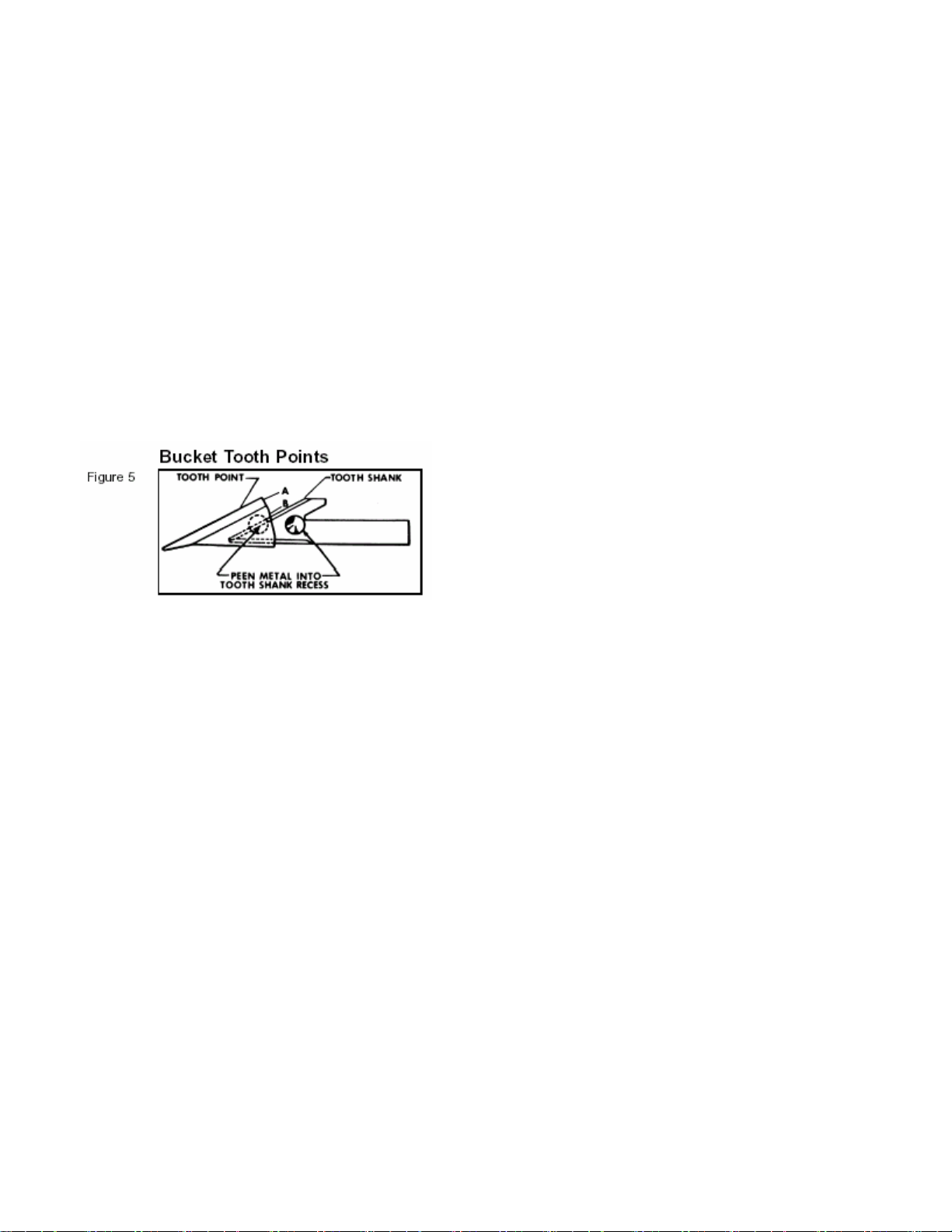
The bucket tooth points are self-sharpening and will require little attention; however, these points on
the bucket shanks can be replaced when they become badly worn or broken.
A tooth points can be removed from the welded tooth shank by hammering at "A" (Figure 5) on the
tooth point or by driving a chisel at "B", just between the tooth point box section and the tooth shank.
Install the new point and anchor it to the shank by peening at the location shown.
If a tooth shank breaks off, becomes damaged or lost so that it cannot hold a tooth point, a new shank
should be welded to the bucket in its place. The newer Style are now bolted on.
Tightening Nuts and Bolts
Periodically, check to be sure all bolts and nuts are tight. See torque chart, page 43.
Check all pivot pins for cotter pins, washers and retainers; if missing, replace.
Lubrication
Economical and efficient operation of the backhoe is dependent upon regular and proper lubrication of
all moving parts with a quality lubricant.
All parts fitted with grease fittings should be lubricated with a good quality chassis lube type grease. If any
grease fittings are missing, replace them immediately. Clean all fittings thoroughly before using grease
gun.
Lubricate all grease fittings at least twice daily, once at the beginning of operation and again approximately

16
halfway through the work day.
Lower stabilizers to the ground, extend dipper stick and bucket and lower boom so bucket rests on the
ground as shown in Figure 7. Refer to these illustrations for the location of all grease fittings.
*IMPORTANT: Before greasing boom to swing frame pivot (
*
) shown in Figure 7, raise boom and install
boom safety lock pin shown in Figure 1.
The following locations should be oiled with SAE 30 oil:
A. Stabilizer Pivot Pins
B. Control Handle Linkage
C. Seat Bracket Pivot
Hydraulic Oil: Most any all purpose Tractor Hydraulic oil can be used, AW32 / AW42 is good.
IMPORTANT: Avoid excessive greasing. Dirt collects on exposed grease and increases wear greatly.
After greasing, wipe off excessive grease from fittings.
① ① ① ① ① ① ①
① ① ① ① ① ① ① ① ①
Figure 5 –Lubrication Points
INSTALLATION AND REMOVAL
Tractor Preparation
1. Remove rockshaft center link.
2. Remove the sway links, lift links, and draft links.
3. Remove drawbar.
The backhoe can be self-assisting during the installation and removal procedures.

17
Installing an Assembled Backhoe on a Tractor
IMPORTANT - Consult the "General Operation" section for proper use and terminology when installing this
backhoe.
1. Center sub frame between tractor rear tires and carefully back over sub frame until hydraulic hoses are
close enough to connect.
2. Stop tractor and set park brake.
3. Disconnect tractor pressure line hose from tractor power beyond hose at rear of tractor. Connect
backhoe pressure line hose to tractor pressure line hose. Connect return hose of backhoe to tank line of
tractor, located on right hand side of tractor, under rockshaft arm.
DANGER
The only time the backhoe should be operated from a position other than the operator's seat is
during the backhoe installation and removal process.
•Engage Swing Lock Pin
•Always stand away from the backhoe stabilizer legs and along side of the tractor rear tires.
CAUTION
Route hydraulic hoses carefully to prevent damage.
4. Start tractor, set throttle at low idle, remove parking brake.
5. Using backhoe hydraulics in the boom and stabilizer leg circuits, raise sub frame enough to align
hooks on sub frame with Tractor lower 3-point hitch connection points.
IMPORTANT - As you raise unit, you will need to alternate back and forth between the boom and stabilizer
circuits. This procedure is needed to keep the front of the sub frame (under the loader mount) as close to
the ground as possible.
6. Roll or drive tractor back until hooks are fully engaged into lower 3-point hitch connection points.
7. Making sure that the Lock Pins and pivoting latches are out of the way in the front of the sub frame,
pivot sub frame up into the Loader Mount Weldment.
Again, this is accomplished by using the boom hydraulics.
8. Shut off tractor and engage parking brake.
9. Secure pivoting latches using Lock Pins and Hair Pin Clips.
Testing Backhoe Hydraulic Hook-Up
1. Start the tractor.
2. Exit the tractor.
3. Sitting in the backhoe operator's seat raise and lower the stabilizer legs and extend and retract the
dipper stick.
4. Exit backhoe, stop engine, and check hydraulic fluid level in tractor.
Removing Assembled Backhoe from Tractor-
1. Start tractor engine, engage park brake, place throttle in low idle position, and exit tractor.
2. Remove Swing Lock Pin from its storage location and install in backhoe.
3. Remove Lock Pins and Hair Pins Clips from front of sub frame. Pivot latches forward to disengage from
loader mount.

18
4. Pivot sub frame down until the sub frame clears the Loader Mount Weldment.
Again, this is Accomplished by using the boom and stabilizer circuit hydraulics.
5. Flip up pivoting latches and reinstall Lock Pins and Hair Pin Clips for storage Purposes.
6. Continuing to use the boom and stabilizer circuit hydraulics, raise sub frame slightly at the Tractor
lower 3-point hitch connection points to take the sub frame weight off of the pins.
IMPORTANT - Watch that hydraulic hoses to backhoe are not kinked or pulled tight.
7. Drive tractor ahead just enough (5" to 6") to clear sub frame hooks from the Tractor lower 3-point hitch
connection points.
8. Again, using boom and stabilizer circuit hydraulics lower backhoe and sub frame to the ground.
9. Shut off tractor, engage parking brake, then disconnect hydraulic hoses from backhoe.
10. Reconnect tractor pressure line hose to tractor power beyond hose, located just above PTO master
shield.
NOTE: For long term storage, coat exposed cylinder rods with grease.
Stabilizer Pads
The backhoe is supplied with flip-over stabilizer pads as standard equipment. They are suitable for
most backhoe work and generally are all that is ever required. However, Street pad kits are available
as an option. This kit bolts to the standard pads and increase the versatility of the backhoe. See figure 10.
Hydraulic Trouble Shooting
The trouble shooting material presented in this section is offered as a guide to diagnosing probable
causes and remedies for general operational problems. Match your problem with the typical problem
examples given, and note the numbers given for the possible cause. These numbers correspond with the
possible cause and correction paragraphs that follow.
NOTE: When using the following chart, if it is decided that an overhaul of components or pressure
adjustments are necessary to correct malfunctioning, it is recommended that your dealer make these
repairs. He is equipped to do this work.
WARNING
Escaping
hydraulic
/
diesel
fluid
under
pressure
can penetrate
the
skin
causing
serious
injury.
Do
not
use
your
hand
to
check
for
leaks.
Use
a
piece
of
cardboard
or
paper
to
check
for
leaks.
Stop
engine
and
relieve
pressure
before
connecting or
disconnecting
lines.
Tighten
all
connections
before
starting
engine
or
pressurizing
lines.
If
any
liquid
is
injected
into
the
skin,
obtain
medical
attention
immediately
or
gangrene
may
result.
Problems
and
Possible
Causes

19
1. Machine fails to operate when started initially -1, 2, 5, 7, 16, 24
2. Machine loses power after operating satisfactory initially - 1, 8, 10, 14, 16, 24
3. Loss of power in lift or crowd cylinder, but other cylinders function properly - 23, 25, 30
Problems
and
Possible
Causes,
Continued
4. Loss of power in any one cylinder including lift and crowd - 8, 9, 10, 11, 12, 13, 23, 25, 26
5. Loss of power in swing cylinders, but other cylinders functioning property - 8, 9, 10, 11, 12, 13, 23, 24,
26
6. Maximum swing action cannot be obtained - 12, 15.
7. Slow operation of machine (lack of power) all cylinders - 1, 4, 6, 14, 16, 24
8. Spongy or jerking action of cylinders and/or noisy operation - 1, 3, 4, 5
9. Lift, crowd or bucket cylinders drop under load when control spools shifted from neutral - 28, 30
10.Load drops or settles - 8, 10, 13, 26, 28
11.Leaky cylinders - 10, 11, 12, 13
12.Leaky valve - 8, 16, 17, 29
13.Sticky valve spool - 17, 20, 21, 22
14.Unable to push valve spool in - 17, 18, 20, 21, 22
15.Spring centered spools do not return to neutral- 17, 18, 19, 20, 21, 22
Causes and Corrections
1. Low oil supply in reservoir - fill to proper level.
2. No oil supply to machine - oil is not being diverted from the prime mover hydraulic system.
Be sure that the proper controls are actuated on the prime mover.
3. Air in system - bleed all circuits of air by operating machine at maximum oil flow and through
full movements.
4. Oil viscosity too heavy, or oil is not at operating temperature - use recommended hydraulic fluid.
Run machine until oil reaches operating temperature.
5. Pump not running - check pump drive to be sure it is engaged.
6. Insufficient pumping - advance engine throttle.
7.
Improper hose connection -
IMPORTANT:
Be
sure
inlet
and
return
hoses
are
hooked
up
correctly
Improper
hook-up
will
result
in
damage
to
the backhoe
valve.
8. Loose oil line connections, leaks in line or broken lines - tighten all hose connections and replace and
damaged O-ring at leaking O-ring fittings. Check and replace any damaged hoses and lines.
9. Restrictions in oil line - check and replace any damaged hoses and lines. Check for pinched hoses.
10.Oil is bypassing cylinder piston, scored piston, worn piston packing, or defective piston assembly
replace or rebuild the cylinder; replace damaged parts.
11.Scored piston rods and worn rod guides in cylinder - replace or rebuild the cylinder; replace damaged
parts.
12. Bent piston rod in cylinder - replace or rebuild the cylinder; replace damaged parts.
13. Worn or damaged rod seals on cylinder; external repack cylinder. Rebuild cylinder, replacing damaged
parts as
necessary.
14. Diverter valve on prime mover leaking externally or bypassing oil internally through valve to reservoir

20
diverter valve may need rebuilding or replacing.
15. Something jamming the swing linkage – remove interference.
16. Excessive back pressure - relief condition. May be restriction from outlet to reservoir.
17. Paint on valve spool; sticking valve spool or scored valve spool - clean valve spool. Binding is usually
caused from an over tightened plug, mounting bolt, fitting in valve body or tie rod bolt. If a plug or
fitting in the valve body is leaking, do not over tighten in an effort to stop leak. This will distort body
casting and cause spools to bind. Instead, the plug and fitting should be removed from valve body and
be reconnected, using a new O-ring. Do not apply excessive pressure on mounting bolts. The rods
should be torqued to 20 ft./lbs. Never force spool, if binding occurs see item 30 at the end.
18. Oil leakage past spool seal into spool cap remove cap. If it contains oil replace spool seal O-rings.
Check O-ring retainer to be sure it is flat. If it has been "belled" check for restriction from outlet to
reservoir of valve which would cause excessive back pressure. See item 30 at the end and item 9.
19. Broken return springs - replace springs, see item 30 at the end and Figure 11.
20. Bent spool - replace with new spool section. See item 30 at the end.
21. Foreign particles - clean system and valve.
22. Misalignment of control handle linkage – check linkage for binding condition.
23. Spool not moved to full stroke - check travel, should be 5/16" either way, or a total of 5/8".
See item 30 at the end.
24. Relief valve setting in backhoe control valve too low or defective - relief pressure will have to
be checked and corrections made. Backhoe system pressure is 2100 psi. Relief valve may
need cleaning and overhauling, or entire cartridge must be replaced. See item 30 at the end.
25. Overload relief valve in the control valve stuck open or malfunctioning - clean relief carefully
but do not disturb its pressure setting as it cannot be field calibrated, or replace cartridge.
See item 30 at the end.
26. Worn control valve - replace the control valve.
27. Check proper in the control valve not holding clean check poppet(s) carefully, being sure that it moves
freely with good spring action and seats properly or replace. See item 30 at the end.
28. Damaged or worn spool seals - replace spool end seals, see item 30 at the end.
29. Ball in check valve is stuck or not seating properly - clean anti-cavitation valve carefully, being sure
that checks move freely and seat properly, or replace cartridge. See item 30 next.
30. Problems involving the control valve proper:
This valve is a precision device and is not intended for any extensive field adjustment or repair. Field
replacement parts are limited to seal kits, cartridges, valve sections and tie rods. Replacement of
these parts, the opening of check cavities and certain relief valve cavities to examine for trapped dirt,
or the resetting of the main relief valve with the use of good pressure gauge, should be referred to
qualified service personnel.
Dirt and shreds of packing material are the usual causes of valve malfunction. Be sure the reservoir oil
supply is kept clean and only factory supplied packings are used in cylinder repair. Everything must be
clean and free of dirt during the oil line removal and replacement, and during any cylinder work.
This manual suits for next models
3
Table of contents
Popular Tractor Accessories manuals by other brands


Hardi
Hardi COMMANDER Classic DELTA Instruction book

BE Ag & Industrial
BE Ag & Industrial BACKHOE BE-BK Series Operations & parts manual

Kverneland
Kverneland Enduro user manual

Avantco
Avantco A440857 Operator's manual

Avantco
Avantco Snow Blower 1150 Operator's manual for Attachment

Avantco
Avantco A36262 Operator's manual for Attachment


