ASA Electronics Jensen MCD5060 User manual

MCD5060
MCD5060
Installation and Operation Manual
MARINE CD PLAYER / RECEIVER
All manuals and user guides at all-guides.com
all-guides.com

MCD5060
2
SAFETY INFORMATION
When Driving
Keep the volume level Iow enough to be aware of the road and traffic conditions.
Protect from Water
Do not expose the product directly to water, as this can cause electrical shorts, fire or other
damage.
Protect from High Temperatures
Exposure to direct sunlight for an extended period of time can produce very high temperatures
inside your vehicle. Give the interior a chance to cool down before starting playback.
Do not mount radio within close proximity of engine compartment.
Use the Proper Power Supply
This product is designed to operate with a 12 volt DC negative ground battery system.
Protect the Disc Mechanism
Avoid inserting any foreign objects into the disc slot. Misuse may cause malfunction or
permanent damage due to the precise mechanism of this unit.
CAUTION:
THIS MOBILE CD PLAYER IS A CLASS I LASER PRODUCT. THIS UNIT USES A VISIBLE/
INVISIBLE LASER BEAM WHICH COULD CAUSE HAZARDOUS RADIATION IF EXPOSED
DIRECTLY. BE SURE TO OPERATE THE MOBILE CD PLAYER AS INSTRUCTED.
USE OF CONTROLS OR ADJUSTMENTS OR PERFORMANCE OR PROCEDURES OTHER
THAN THOSE SPECIFIED HEREIN MAY RESULT IN HAZARDOUS RADIATION
EXPOSURE.
DO NOT OPEN COVERS AND DO NOT REPAIR BY YOURSELF. PLEASE REFER
SERVICING TO A QUALIFIED TECHNICIAN.
WARNING:
• TO REDUCE THE RISK OF FIRE OR ELECTRIC SHOCK, DO NOT EXPOSE THIS
EQUIPMENT DIRECTLY TO WATER.
• TO REDUCE THE RISK OF FIRE OR ELECTRIC SHOCK AND INTERFERENCE, USE
ONLY THE RECOMMENDED ACCESSORIES.
• THIS DEVICE IS INTENDED FOR CONTINUOUS OPERATION.
DISC NOTES
Compatible Disc Types
NOTE: CD-R and CD-RW discs will not play unless the recording session is closed and
the CD is finalized.
Disc Maintenance
• A dirty or defective disc may cause sound dropouts while playing. Before playing, wipe
the disc using a clean cloth, working from the center hole towards the outside edge.
Never use benzene, thinners, cleaning fluids, anti-static liquids or any other solvent.
• Be sure to use only round CDs for this unit and do not use any special shape CDs. Use of
special shape CDs may cause the unit to malfunction.
• Do not stick paper or tape on the disc. Do not use CDs with labels or stickers attached or
that have sticky residue from removed stickers.
• Do not expose discs to direct sunlight or heat sources such as hot air-ducts, or leave them
in a vehicle parked in direct sunlight where there can be a considerable rise in
temperature inside the vehicle.
NOTE: A disc may become scratched (although not enough to make it unusable)
depending on how you handle it and other conditions in the usage environment. These
scratches are not an indication of a problem with the player.
Table 1: General Disc Information
Disc Type Logo Diameter/
Playable Sides Playback Time
Audio CD 12 cm single side 74 minutes
REWRITABLE
RECORDABLE
Insert label Do not bend. Never touch
the under side
of the disc.
Wipe clean from
the center to the
edge.
side up.
All manuals and user guides at all-guides.com

MCD5060
3
INSTALLATION
Before You Begin
1. Disconnect Battery
Before you begin, always disconnect the battery negative terminal.
2. Remove Transport Screws
Important Notes
• Before final installation, test the wiring connections to make sure the unit is connected
properly and the system works.
• Use only the parts included with the unit to ensure proper installation. The use of
unauthorized parts can cause malfunctions.
• Consult with your nearest dealer if installation requires the drilling of holes or other
modifications to your vehicle.
• Install the unit where it does not interfere with driving and cannot injure passengers if
there is a sudden or emergency stop.
• If the installation angle exceeds 30º from horizontal, the unit might not give optimum
performance.
• This unit is not waterproof and is intended for interior mounting applications only.
Exterior mounting of the unit requires use of an ASA approved marine housing.
• Avoid installing the unit where it will be subject to high temperatures from direct sunlight,
hot air, or from a heater, or where it would be subject to excessive dust, dirt or vibration.
• Be sure to remove the control panel before installing the unit.
DIN Front/Rear Mount
This unit can be property installed with either a “Front” (conventional DIN front mount) or “Rear”
(DIN rear mount installation, utilizing threaded screw holes at the sides of the unit chassis)
mount. For details, refer to installation methods A and B.
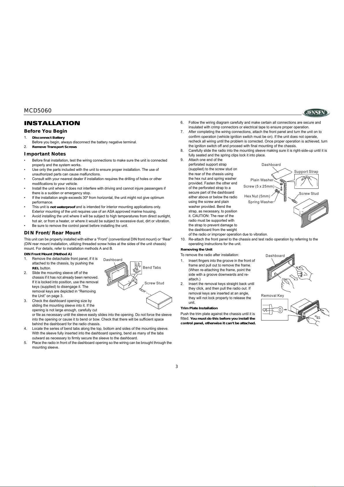
DIN Front Mount (Method A)
1. Remove the detachable front panel, if it is
attached to the chassis, by pushing the
REL button.
2. Slide the mounting sleeve off of the
chassis if it has not already been removed.
If it is locked into position, use the removal
keys (supplied) to disengage it. The
removal keys are depicted in “Removing
the Unit” on page 3.
3. Check the dashboard opening size by
sliding the mounting sleeve into it. If the
opening is not large enough, carefully cut
or file as necessary until the sleeve easily slides into the opening. Do not force the sleeve
into the opening or cause it to bend or bow. Check that there will be sufficient space
behind the dashboard for the radio chassis.
4. Locate the series of bend tabs along the top, bottom and sides of the mounting sleeve.
With the sleeve fully inserted into the dashboard opening, bend as many of the tabs
outward as necessary to firmly secure the sleeve to the dashboard.
5. Place the radio in front of the dashboard opening so the wiring can be brought through the
mounting sleeve.
6. Follow the wiring diagram carefully and make certain all connections are secure and
insulated with crimp connectors or electrical tape to ensure proper operation.
7. After completing the wiring connections, attach the front panel and turn the unit on to
confirm operation (vehicle ignition switch must be on). If the unit does not operate,
recheck all wiring until the problem is corrected. Once proper operation is achieved, turn
the ignition switch off and proceed with final mounting of the chassis.
8. Carefully slide the radio into the mounting sleeve making sure it is right-side-up until it is
fully seated and the spring clips lock it into place.
9. Attach one end of the
perforated support strap
(supplied) to the screw stud on
the rear of the chassis using
the hex nut and spring washer
provided. Fasten the other end
of the perforated strap to a
secure part of the dashboard
either above or below the radio
using the screw and plain
washer provided. Bend the
strap, as necessary, to position
it. CAUTION: The rear of the
radio must be supported with
the strap to prevent damage to
the dashboard from the weight
of the radio or improper operation due to vibration.
10. Re-attach the front panel to the chassis and test radio operation by referring to the
operating instructions for the unit.
Removing the Unit
To remove the radio after installation:
1. Insert fingers into the groove in the front of
frame and pull out to remove the frame.
(When re-attaching the frame, point the
side with a groove downwards and re-
attach.)
2. Insert the removal keys straight back until
they click, and then pull the radio out. If
removal keys are inserted at an angle,
they will not lock properly to release the
unit.
Trim Plate Installation
Push the trim plate against the chassis until it is
fitted. You must do this before you install the
control panel, otherwise it can't be attached.
182
53
Dashboard
Bend Tabs
Screw Stud
Dashboard
Plain Washer
Screw (5 x 25mm)
Hex Nut (5mm)
Spring Washer
Screw Stud
Support Strap
Dashboard
Removal Key
All manuals and user guides at all-guides.com

MCD5060
4
DIN Rear Mount (Method B)
This unit has threaded holes in the chassis side panels which may be used with the original
factory mounting brackets of some vehicles to mount the radio to the dashboard. Please
consult with your local mobile stereo shop for assistance on this type of installation.
1. Remove the existing factory radio from the dashboard or center console mounting. Save
all hardware and brackets as they will be used to mount the new radio.
2. Carefully unsnap the plastic trim ring from the front of the new radio chassis. Remove and
discard the trim ring.
3. Remove the factory mounting
brackets and hardware from
the existing radio and attach
them to the new radio. Select
a position where the screw
holes of the bracket and the
screw holes of the main unit
are aligned (are fitted).
Tighten the screws at 2
places on each side. Do not
exceed M5 x 9 MM maximum
screw size. Longer screws
may damage components
inside the chassis.
4. Wire the new radio to the
vehicle as outlined in the Universal Installation instructions.
5. Mount the new radio assembly to the dashboard or center console using the reverse
procedure of step 1.
NOTE: The mounting box, outer trim ring, and half-sleeve are not used for method B
installation.
Reconnect Battery
When wiring is complete, reconnect the battery negative terminal.
Detachable Control Panel (DCP)
Removing the Detachable Control Panel (DCP)
1. Turn the power off.
2. Press the REL button.
3. Remove the DCP.
Attaching the DCP
1. Attach the panel at the right side first, with point B on the
main unit touching point A on the DCP (as shown in the
diagram).
2. Press the left side of the DCP onto the main unit until a
“click” is heard.
CAUTION:
• DO NOT insert the DCP from the left side. Doing so may
damage it.
• The DCP can easily be damaged if dropped or subjected to a strong shock. When the
release button is pressed and the DCP is unlocked, the vehicle's vibrations may cause it
to fall. To prevent damage to the DCP, always store it in a protective case after detaching
it.
• The rear connector that connects the main unit and the DCP is an extremely important
part. Be careful not to damage it by pressing on it with fingernails, pens, screwdrivers, etc.
• If the DCP is dirty, remove debris with a soft, dry cloth only. You can use a cotton swab
soaked in isopropyl alcohol to clean the socket on the back of the DCP.
Screws
Dashboard
Factory
Mounting
Bracket
Hook (Remove)
PANEL RELEASE
BUTTON
B
A
2
1
All manuals and user guides at all-guides.com

MCD5060
5
WIRING
Power Antenna
Connect to power antenna or amplifier,
If not used, tape bare end of wire.
Ground
Connect to ground terminal or clean
unpainted metal part of chassis.
Memory / Battery
Connect to battery or 12 volt power source
that is always live. The radio will not work if
this wire is not connected.
Accessory / Ignition
Connect to existing radio wire or radio fuse.
12345678910
11 12 13 14 15 16 17 18 19 20
Figure 1: 20 PIN HARNESS PIN CHART
PIN WIRE COLOR FUNCTION / LABEL
1
2
3
4
5
6
7
8
9
10
11
12
13
14
15
16
17
18
19
20
GREY / BLACK
GREY
VIOLET
VIOLET/BLACK
GREEN
GREEN / BLACK
RED
BLACK
RED
WHITE
WHITE / BLACK
BLUE
YELLOW
BLACK
WHITE
RIGHT FRONT SPEAKER ( )
LEFT REAR SPEAKER (+)
N/A
LEFT FRONT SPEAKER (+)
CHASSIS GROUND
LEFT REAR PRE-AMPLIFIER LINE OUT
LEFT FRONT SPEAKER ( )
POWER ANTENNA
BATTERY (+)
RIGHT FRONT SPEAKER (+)
RIGHT REAR SPEAKER (+)
RIGHT REAR SPEAKER ( )
LEFT REAR SPEAKER ( )
IGNITION (ACC)
REAR PRE-AMPLIFIER LINE OUT COMMON
RIGHT REAR PRE-AMPLIFIER LINE OUT
EMPTY
GREY-BLACK RF-
VIOLET-BLACK RR-
RED
YELLOW
BLACK
BLUE
VIOLET RR+
GREY RF+
GREEN-BLACK LR-
WHITE-BLACK LF-
GREEN LR+
WHITE LF+
RIGHT REAR
RIGHT FRONT
LEFT REAR
LEFT FRONT
GREY
688A
FUSE
REAR LINE OUT
RED
R-CH
WHITE
L-CH
AMP
HARNESS
AUDIO/POWER
20-PIN
(See Figure 1)
ANTENNA
JACK
RCA-TO-RCA CABLE
(not supplied)
ANTENNA SOCKET
N/A
EMPTY
N/A
EMPTY
N/A
EMPTY
N/A
EMPTY
All manuals and user guides at all-guides.com
Table of contents
Other ASA Electronics Marine Equipment manuals