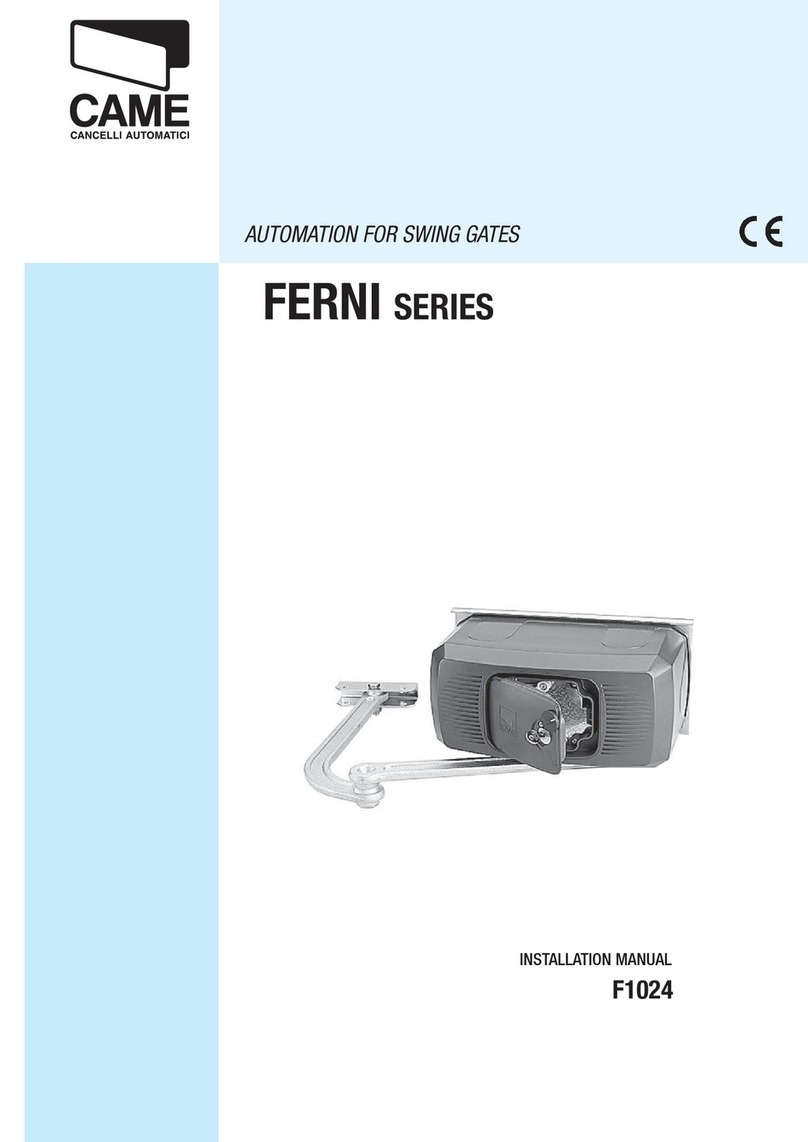
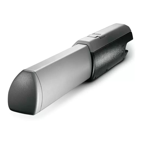
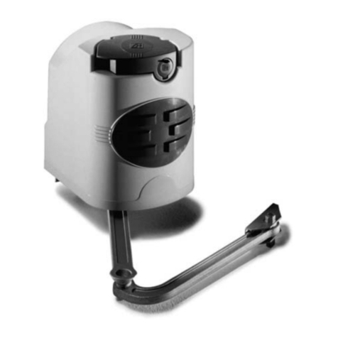
CAME U 1400 Operating instructions

Installation type:
1) Groupe moteur
gauche
2) Groupe moteur droit
3) Armoire de commande
4) Récepteur radio
5) Photocellule de
sécurité
6) Sélecteur à clé
7) Clignotant de
mouvement
8) Nantenne de réception
9) Colonne pour
photocellule
10) Emetteur radio
Standard installation
:
1) Left-hand motor unit
2) Right-hand motor unit
3) Control panel
4) Radio reveicer
5) Safety photocell
6) Key-operated selector
switch
7) Flashing light
8) Receiving antenna
9) Photocell column
10) Radio transmitter
Impianto tipo:
1) Gruppo motore sx
2) Gruppo motore dx
3) Quadro comando
4) Ricevitore radio
5) Fotocellula di sicurez-
za
6) Selettore a chiave
7) Lampeggiatore di movi-
mento
8) Antenna di ricezione
9) Colonnina per fotocel-
lula
10) Trasmettitore radio
Instalación tipo:
1) Conjunto motor izq.
2) Conjunto motor der.
3) Cuadro de mandos
4) Radiorreceptor
5) Fotocélula de
seguridad
6) Selèctor con llave
7) Lámpara intermitente
8) Antena de recepción
9) Columna para
fotocélula
10) Transmisor
Standard montage:
1) Motoreinheit, links
2) Motoreinheit, rechts
3) Steuergerät
4) Funkempfänger
5) Sicherheits-Photozelle
6) Schlüsselschalter
7) Blinkmeldeleuchte
8) Empfangsantenne
9) Lichtschrankeensäule
10) Handsender
Automazione esterna per cancelli a battente con motoriduttore KRONO
External automatic opening system for wing gates with KRONO gearmotor
Automatisme axtérieur pour portails à battant avec motoréducteur KRONO
Externe Automatik für Flügeltore mit KRONO getriebemotor
Automatizacion exterior para puertas batientes con motorreductor KRONO
11
6
5
4 x 1,5
2 x 1
4 x 1,5
2 x 1,5 T RG 58
3 x 1,5
230 V
78
3
4
1
2
4 x 1 - RX
2 x 1 - TX
4 x 1 - RX
9
9
10
2 x 1 - TX
Documentazione
Tecnica
S59
rev. 0.1
del 03/00
©
CAME
CANCELLI
AUTOMATICI
119DS59
SET
COMPLETE
U 1400

2
Descrizione:
- Automazione esterna per cancelli a battente;
- Progettato e costruito interamente dalla CAME S.p.A., rispon-
de alle vigenti norme di sicurezza UNI 8612, con grado di pro-
tezione IP 54;
- Garantito 12 mesi salvo manomissioni.
Versioni:
KR 300 S
Versione sinistra;
KR 300 D
Versione destra;
KR 310 S
Versione sinistra con finecorsa in apertura e chiusura;
KR 310 D
Versione destra con finecorsa in apertura e chiusura.
Limiti d'impiego:
- Dimensione ante fino a 3 metri;
- Apertura dell’anta: max 120°;
- I valori indicati (vedi tab. 2 a pag. 4) sono validi per un servi-
zio ad uso residenziale; per un servizio intensivo ridurre tali
valori dal 10 al 20%.
Accessori:
KR001
Serratura a chiave personalizzata.
Description:
- External automating opening system for wing gates;
- Designed and constructed entirely by CAME in compliance
with current safety standards (UNI 8612), and with an IP54
protecting rating;
- Guaranteed for 12 months, unless tampered with by
unauthorized personnel.
Versions:
KR 300 S
Left side model ;
KR 300 D
Right side model ;
KR 310 S
Versione sinistra con finecorsa in apertura e chiusura;
KR 310 D
Versione destra con finecorsa in apertura e chiusura.
Operational limits:
- Door height up to 3 meters;
- Maximum opening of wing: 120°;
- The values shown (see table 2 on page 4) refer to normal
residential use;for more intensive use, these values should be
reduced by 10 to 20%.
Accessories:
KR001
Personalised key lock.
GENERAL SPECIFICATIONS
ENGLISH
CARATTERISTICHE GENERALI
ITALIANO

3
Descripción:
- Automatizacion exterior para puertas batientes;
- Diseñado y fabricado enteramente por CAME S.p.A., cumple
con las normas de seguridad vigentes UNI 8612, con grado
de protección IP54;
- Garantizado 12 meses, salvo manipulaciones.
Modelos:
KR 300 S
Versión izqierda;
KR 300 D
Version derecha;
KR 310 S
Versión izqierda con final de carrera en apertura y cierre;
KR 310 D
Version derecha con final de carrera en apertura y cierre.
Description:
- Automatisme extérieur pour portails à battant;
- Conçu et construit entièrement par CAME, correspondant aux
normes de sécurité in vigueur (NFP 25-362) avec un degré de
protection IP 54;
- Il est garanti 12 mois sauf en cas d’altérations.
Versions:
KR 300 S
Version gauche;
KR 300 D
Version droite;
KR 310 S
Version gauche avec interrupteur de fin de course en ouverture
et fermeture;
KR 310 S
Version droite avec interrupteur de fin de course en ouverture
et fermeture.
Limites d'emploi:
- Dimensions des portes jusq’a’ 3 mètres;
- L’ouverture standard maximum de la porte est de 120°;
- Les valeurs indiquées (voir tableau 2 - pag. 4) sont valables
pour un service à usage résidentielle; pour un service
particuliérement intensif, il convient de réduire ces valeurs de
10 a 20%. Accessoires:
KR 001
Serrure avec clé personalisée.
Baschreibung:
- Externe Automatik für Flügeltore;
- Vollkommen von der CAME S.p.A. den geltenden
Sicherheitsnormen (UNI 8612) entsprechend entwickelt und
hergestellt. Schutzklasse IP 54;
- Garantie: 12 Monate, vorbehaltlich unsachgemäßer
Handhabung und Montage.
Ausführungen:
KR 300 S
Linke Version;
KR 300 D
Rechte Version;
KR 310 S
Linke Version mit Endanschlag beim Öffnen und Schließen;
KR 310 D
Rechte Version mit Endanschlag beim Öffnen und Schließen.
Einsatzbereich:
- Torflügeldimensionen bis 3 Meter;
- Maximale Standard Toröffnung: 120°;
- die angegebenen Werte (Siehe Tabelle 2 auf Seite 4) gelten
fürdenEinsatzinWohnanlagen;beibesonders starkemFinsatz
sind diese Werte un 10% bis 20% zu reduzieren.
Zubehör:
KR 001
Schloß mit personalisiertem Schlüssel.
CARACTERÍSTICAS GENERALES
ESPAÑOL
Limites de empleo:
- Dimensión hojas hasta 3 metros;
- Apertura standard máxima de la hoja: 120°;
- Los valores indicados (ver tab. 2 - pag. 4) valen para el uso
residencial; para un servicio más intensivo es preciso reducir
dichos valores de 10 al 20%.
Accesorios:
KR 001
Cerradura con llave personalizada.
GENERAL SPECIFICATIONS
DEUTSCH
CARACTÉRISTIQUES GÉNÉRALÉS
FRANÇAIS

4
* Ottenuta mediante quadro comando CAME
* Obtained with CAME control panel
* Obtenue au moyen armoire de commande CAME
* Regulierbarer schub erreicht mit Hilfe der CAME Motorsteuerrung
* Empuje regulable obtenido mediante tablero de control CAME
atnaazzehgraL
gniwetagfohtdiW
liatnavudrueugraL
etierblegülfroT
atreupohcnA
atnaoseP
gniwetagfothgieW
liatnavudsdioP
thciweglegülfroT
atreuposeP
00.2m 008gK
05.2m 006gK
00.3m 004gK
Tab. 1
Tab. 2
CARATTERISTICHETECNICHE -
TECNICHAL CARACTERISTICS
- CONTRÔLES GENERALES -
ALLGEMEINE PRÜFUNGEN
CONTROLES GENERALES
956
194
113
234
304
Corsa
Stroke
Course
Lauf
Recorrido
LIMITI D'IMPIEGO -
USE LIMITS -
LIMITES D'EMPLOI -
VERWENDUNGSBEREICH -
LIMITES DE EMPLEO
MISURE D'INGOMBRO -
EXTERNAL DIMENSIONS
- MEASURES D'ENCOMBRENT -
ABMESSUNGEN
- DIMENSIONES
MOTORIDUTTORE GRADO DI
PROTEZIONE PESO ALIMENTAZIONE ASSORBIMENTO POTENZA INTERMITTENZA
LAVORO SPINTA TEMPO CORSA CONDENSATORE
GEARMOTOR PROTECTION
RATING WEIGHT POWER SUPPLY CURRENT POWER DUTY CICLE PUSH TRAVEL TIME CAPACITOR
MOTORÉDUCTEUR DEGRÉ DE
PROTECTION POIDS ALIMENTATION ABSORPTION PUISSANCE INTERMITTENCE
DE T RAVAIL POUSSÉE TEMPS COURSE CONDENSATEUR
GETRIEBEMOTOR SCHUTZGRAD GEWICHT STROM_
VERSORGUNG STROMAUFNAHME LEISTUNG EINSCHALTDAUER REGELBARER LAUFZEIT KONDENSATOR
MOTORREDUCTOR GRADO DE
PROTECCION PESO ALIMENTACION ABSORBENCIA POTENCIA INTERMITENCIA
TRABAJO EMPUJE TIEMPO DE
RECORRIDO CONDENSADOR
KRONO IP 54 10 Kg 230V a.c. 1,1 A 130W 30 % * Max
3000 N 22 s (90°) 8 µF

5
Comprobar que:
- la estructura de la
puerta sea oportu-
namente recia y que
los goznes estén
lubricados;
- la medida C no
exceda de 60 mm.(50
mm. para aperturas
de hasta 120°), de no
ser así es necesario
actuar sobre el pilar
de modo que alcance
dicha medida.
Überprüfen:
- ob die Torstruktur
ausrelchend robust ist
und ob die Angel-
zapfen geschmiert
sind;
- ob das Maß C 60 mm
nicht überschreitet (50
mm bei Toröffnung bis
zu 120°), sollte dies
nicht der Fall sein, der
Torpfosten dement-
sprechend anpassen.
Controllare che:
- la struttura del cancel-
lo sia adeguatamente
robusta e che i cardi-
ni siano lubrificati;
- la misura C non sia su-
periore a 60 mm (50
mm per aperture fino
a 120°), in caso con-
trario è necessario in-
tervenire sul pilastro
in modo da raggiun-
gere tale misura.
Make sure:
- that the structure of the
gate is sufficiently
strong, and that the
hinges are lubricated;
- that distance C does
not exceed 60 mm (50
mm for opening angles
of up to 120°).
If distance C exceeds
these values the pillar
must be modified so
that the proper
distance is respected.
Vérifier que:
- la structure du portail
soit suffisamment ro-
busteet que les pivots
coulissent correc-
tement;
- la mesire C ne
dépasse pas 60 mm
(50 mm pour des
ouvertures jusqu’à
120°). Dans le cas
contraire, il est
nécessaire d’interve-
nir sur le pilier de
façon à obtenir cette
mesure.
Pilastro
Pillar
Pilier
Pfosten
Pilar
C max.
Hinge
Gozne
Angelzapfen
Cardine
Pivot
Gate wing
Hoja
Torflügel
Anta
Vantail
CONTROLLI GENERALI -
GENERAL CONTROL PROCEDURE -
CONTRÔLES GÉNÉRAUX -
ALLGEMEINE PRÜFUNGEN
CONTROLES GENERALES

6
Den hinteren Bügel unter
Einhaltung der Maße A
und B (Tab. 3) zwischen
Angelzapfen und der
zentralen Bügelbohrung,
die zur Montage des
Getriebmotors dient,
befestigen.
Der hintere Bügel ist mit
einer Reihe von
Bohrungenversehen, die
die Montage des Getrie-
bemotors erleichtern
sowieeineÄnderungdes
Toröffnungswinkels
erlauben. Entsprechend
der Angelzapfenposition
am Torpfosten kann der
hintere Bügel verlängert
bzw. verkürzt werden.
Fixér l’étrier arrière en
respectant les cotes A
et B (Tabl. 3) entre le
gond du portail et le
trou central de l’étrier
(sur lequel sera fixé le
motoréducteur).
L’étrier arrière
comprend d’autres
perforations pour
faciliter le montage du
motoréducteur ou pour
modifier l’angle d’ou-
verture du portail.
Suivant l’installation et
la position du gond du
portail (par rapport au
pilier), il est possible
d’allonger ou de
raccourcir l’étrier
arrière.
Install the rear bracket
while respecting
distances A and B (Tab.
3) between the hinge on
the gate and the hole in
the centre of the bracket
(whichis usedto holdthe
gear motor).
The rear bracket is
equipped with additional
holesto makeinstallation
of the gear motor easier,
or to change the opening
angle of the gate.
The rear bracket can be
lengthened or shortened
to suit the individual
installation site and the
positionof the gate hinge
(with respect to the
pillar).
Fissare la staffa di coda
rispettando le quote A
e B (Tab. 3) tra il cardi-
ne del cancello e il foro
centrale della staffa
(sulla quale deve esse-
re fissato il motori-
duttore).
La staffa di coda è do-
tata di ulteriori forature
per agevolare il mon-
taggio del motori-
duttore o per variare
l’angolo di apertura del
cancello. A seconda
dell’installazione e del-
la posizione del cardi-
ne del cancello (rispet-
to al pilastro) è possi-
bile allungare o accor-
ciare la staffa di coda.
Fijar en soporte trasero
respetando las
medidas A o B (Tabla 3)
entre el gozne de la
puerta y el agujero
central del soporte (en
que se debe fijar el
motorreductor).
El soporte trasero está
dotado de otros
agujeros para sim-
plificar el montaje del
motorreductor o para
variar el ángulo de
apertura de la puerta.
En función de la
instalación y de la
posición del gozne de
la puerta metálica (con
relación al pilar) es
posible alargar o
acortar el soporte
trasero.
Tab. 3
MONTAGGIO -
ASSEMBLY
- MONTAGE -
MONTAGE
- MONTAJE
1
B
A
TIPO
TYPE
TYPE
TYPE
TIPO
APERTURA
OPENING ANGLE
OUVERTURE
Ö
FFNUNG
APERTURA
A
mm B
mm C
mm E
mm
KRONO 3 90° 130 130 60 910
120° 110 50

7
With the gate closed,
install the front bracket
on the gate wing. The
front bracket, when
installed, must be
aligned along the
horizontal axisof the rear
bracket (see figure) and
the distance between the
centre axes of the
brackets must be 910
mm.
Fixer l’étrier avant sur
le vantail du portail
(vantail en position
fermée), de façon à
obtenir un axe
horizontal avec l’étrier
arrière et avec l’entraxe
comme indiqué sur le
schéma (910 mm).
Bei geschlossenem Tor,
den vorderen Bügel auf
gleicher Achse des
hinteren Bügels und mit
einem Achsabstand
gemäß Abbildung (910
mm.) am Torflügel
befestigen.
Estando la puerta
metálica cerrada, fijar
el soporte delantero en
la hoja de la puerta, en
línea horizontal con el
soporte trasero y con la
distancia entre los ejes
indicada (910 mm.).
A cancello chiuso, fis-
sare la staffa di testa
sull’anta del cancello,
in asse orizzontale con
la staffa di coda e
interasse come indica-
to (910 mm.).
Procedere al montag-
gio del motoriduttore
alle due staffe.
Install the gear motor on
the two brackets.
Réaliser le montage du
motoréducteur sur les
deux étriers.
Getriebemotor auf beide
Bügel montieren.
Montar el motor-
reductor en los dos
soportes.
3
2
Staffa di coda
Rear bracket
Etrier arriére
Hinterer Bügel
Soporte trasero
Livellare le staffe
Levelling the brackets
Mettre les étrier de niveau
Bügel ausrichten
Nivelar los soportes
Staffa di testa
Front bracket
Etrier avant
Vorderer Bügel
Soporte delantero
E = 910
Viti ø 3,9 x 9,5
Screws 3,9 x 9,5
Vis 3,9 x 9,5
Schrauben 3,9 x 9,5
Tornillos 3,9 x 9,5
Vite M8 x 35
Screws M8 x 35
Vis M8 x 35
Schrauben M8 x 35
Tornillos M8 x 35
Boccola
Bush
Douille
Buchse
Casquillo Rosetta ø 12
ø 12 Washer
Rondelle ø 12
Unterlegscheibeø12
Arandela ø 12
Dado M8
M8 nut
Ecrou M8
Mutter M8
Tuerca M8
Dado M12
M12 nut
Ecrou M12
Mutter M12
Tuerca M12
Viti ø 3,9 x 9,5
Screws 3,9 x 9,5
Vis 3,9 x 9,5
Schrauben 3,9 x 9,5
Tornillos 3,9 x 9,5

8
Prevedere una battuta
di arresto meccanico
(ben fissata al suolo) in
chiusura per evitare
l’oltrecorsa anta
motoriduttore.
Install a mechanical
doorstop (which must be
solidly implanted in the
ground) at the closed
points of the gate wing to
prevent the gate wing
from exceeding its
maximum travel at the
open and closed
positions.
Prévoir un dispositif
d’arrêt mécanique
(correctement fixé au
sol) dans la phase de
fermeture afin d’éviter
une course excessive
vantail/motoréducteur.
Einen mechanischen
Endanschlag (gut am
Boden befestigt) in
Öffnungs vorsehen; dies
um Torüberlauf des
Getriebemotors zu
verhindern.
Disponer un tope (bien
fijado en el suelo) para
el cierre para evitar que
la carrera de la hoja
motorreductor sobre-
pase el umbral.
4
Battuta
Doorstop
Dispositif d'arrêt
Anschlag
Tope
Anta
Gate wing
Torflügel
Hoja
Vantail
Battuta (solo per KR300 D/S)
Doorstop (only for KR300 D/S)
Dispositif d'arrêt (uniquement pour KR300 D/S)
Anschlag (Stop) - nur bei KR300 D/S
Tope (sólo para KR300 D/S)

9
- Eseguire i collega-
menti elettrici, come
indicato sull’apposita
etichetta fissata sul
motoriduttore stesso
(Fig. 1);
- per il cavo di collega-
mento utilizzare l’ap-
posito pressacavo
(part. A) in dotazione
fissandolo alla
calottina porta-con-
densatore (part. B).
- Wire the gear motor by
following the wiring
diagram on the label
which is fastened to the
gear motor. (Fig. 1);
-forthecableconnection,
use the appropriate
cable clamp (part. A)
supplied, fixing it to the
capacitor support (part.
B).
- Brancher le
motoréducteur de la
manière indiquée sur
l’étiquette appliquée
sur le motoréducteur
(Fig. 1);
- pour le câble de
branchement, utiliser
le serre-câble (pièce
A) fourni de série en le
fixant à la calotte por-
te- condensateur
(pièce B).
- Den Getriebemotor
gemäß des Motor-
schildesanschließen
(Abb. 1);
- für das Anschlußkabel
die mitgelieferte
kabelführung (A)
verwenden, die am
Deckel der Konden-
satorhalterung (B)
angebracht wird.
- Conectar el
motorreductor como
se indica en la
etiqueta específica
incorporada al motor-
reductor (Fig. 1);
- para el cable de
conexión use el
sujetador de cable
(det. A) de serie
fijándolo a la tapa
portacondensador
(det. B).
COLLEGAMENTO ELETTRICO -
ELECTRICAL CONNECTONS
- BRANCHEMENTS ÉLECTRIQUES
ELEKTRISCHE ANSCHLÜSSE
- CONEXIONES ELÉCTRICAS
5
- Per le regolazioni dei
finecorsa in apertura e
chiusura, agire sulla
vite A per il finecorsa
APRE, sulla vite C per
il finecorsa CHIUDE.
Fig 1
Terra
Ground
Terre
Erde
Tierra
UVW
Morsettiera
Terminal block
Borne
Klemmenleiste
Caja de terminales
U/XV/YW
Part. A Part. B
REGOLAZIONE FINECORSA -
LIMIT SWITCH ADJUSTMENT
- RÉGLAGE INTERRUPTEURS DE FIN DE COURSE
EINSTELLUNG ENDANSCHLAG
- REGULACIÓN DEL FINAL DE CARRERA
- Pour régler les
interrupteurs de fin de
course en ouverture et
fermeture, agir sur la
vis A pour l’inter-
rupteur de fin de
course en OUVRIR et
sur la vis C pour
l’interrupteur de fin de
course FERMER.
- Para la regulación de
los finales de carrera
de apertura y cierre,
gire el tornillo A para
el final de carrera
ABRIR, y el tornillo C
para el final de carrera
CERRAR.
- for opening and closing
limitswitchadjustments,
turn screw A for the
OPEN limit switch, turn
screw C for the CLOSE
limit switch.
- Zur Einstellung vom
Endanschlag an der
Schraube A für den
Endanschlag ÖFFNEN
und an der Schraube C
für den Endanschlag
SCHLIESSEN drehen.
+
+
A
C
C
KR310 S
+
+
KR310 D

10
SBLOCCO MOTORIDUTTORE -
GEAR RELEASE
- OPÉRATION DE DÉBLOCAGE -
ANTRIEBSENTRIEGELUNG
DESBLOQUEO MOTORREDUCTOR
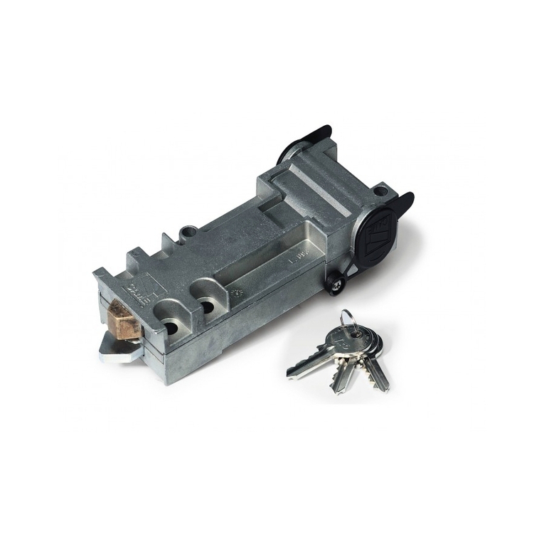
- Inserire la chiave (A)
nella serratura ,ruotar-
la per permettere alla
leva di sblocco (B) di
sganciarsi ed estrarre
la chiave (fig. 2-3);
ruotare quindi la leva
disbloccodi 90° in uno
dei due sensi (fig. 4).
- Per ribloccare l’anta, ri-
portare la leva di
sblocco nella posizio-
ne iniziale (fig. 5).
AB
Fig 2 Fig 3 Fig 4
Fig 5
- Introduire la clé (A)
dans la serrure, tour-
ner pour permettre au
levier de dèblocage
(B) de se décrocher et
extraire la clé (fig.2-3);
tourner ensuite le
levier de déblocage de
90° dans un des deux
sens (fig. 4).
- Introduzca la llave (A)
en la cerradura, gírela
para que la palanca de
dsbloqueo (B) se de-
senganche y extraiga
la llave (fig. 2-3);
entonces gire la
palanca de desblo-
queo 90° en una des
las dos direcciones
(fig. 4).
- Insert key (A) in the
keylock, turn it to allow
the release lever (B) to
unlock and remove the
key (fig. 2-3); then turn
the release lever 90° in
either direction (fig. 4).
-DenSchlüssel(A)indas
Schloß stecken und
drehen, damit der
Entriegelungshebel (B)
freigegeben wird und
denSchlüsselabziehen
(Abb.2-3) Anschließend
denEntriegelungshebel
um 90° in eine der
beiden Richtungen
drehen (Abb. 4).
- Pour bloquer à
nouveau le vantail,
remettre le levier de
déblocage dans sa
positioninitiale(fig.5).
- Para volver a bloquear
la hoja, coloque
nuevamente la palan-
ca de desbloqueo en
la posición inicial (fig.
5).
-To relockthedoor,reset
the release lever to the
initial position (fig. 5).
-Um denTorflügel wieder
zu verriegeln, den
Entriegelugshebel zu-
rüch in die Aus-
gangsstellung bringen
(Abb. 5).

11
MANUTENZIONE PERIODICA /
PERIODIC MAINTENANCE /
ENTRETIEN PERIODIQUE /
REGELMÄßIGE WARTUNG
MANTENIMIENTO PERIÓDICO
- Lubrificare la testa nylon e i perni di rotazione;
- Controllare le viti di fissaggio;
- Verificare l'integrita' dei cavi di collegamento.
- Lubricate the nylon head and the rotation pins;
- Ceck the clamps screws;
- Ceck the connection cable's soundness.
- Lubrifier la tête en nylon et les goujons de rotation;
- Contrôler les vis de fixation;
- Contrôler l'intégrité des câbles de branchement.
- Den Nylonkopf und die Drehzapfen abschmieren;
- Kontrollieren Sie die Befestigungsschrauben.
- Kontrollieren Sie, ob die Anschlußkabel unversehrt sind.
- Lubrique la cabeza nylon y los pernos de rotación;
- Controle los tornillos de sujeción;
- Controle el estado de los cables de conexión.

NOTE /
NOTES
/ NOTE /
HINWEIS
/ NOTA
CAME CANCELLI AUTOMATICI S.P.A.__ITALIA
VIA MARTIRI DELLA LIBERTÀ, 15
31030 DOSSON DI CASIER
TREVISO
CAME SUD S.R.L.__________________ITALIA
VIA FERRANTE IMPARATO, 198
CM2 LOTTO A/7
80146 NAPOLI
CAME FRANCE S.A._______________FRANCE
7 RUE DES HARAS
92737 NANTERRE CEDEX
CAME AUTOMATISMOS S.A._______ESPAÑA
C/JUAN DE MARIANA, 17
28045 MADRID
CAME GMBH______________DEUTSCHLAND
BERGSTRASSE, 17/1
70825 KORNTAL
STUTTGART
CAME GMBH______________DEUTSCHLAND
AKAZIENSTRASSE,9
16356 SEEFELD
internet
www.came.it
e-mail
N° 12 100 8953
NUMERO VERDE
800-295830
ASSISTENZA TECNICA
Table of contents
Other CAME Gate Opener manuals
Popular Gate Opener manuals by other brands

DoorKing
DoorKing 9150 Series Installation & owner's manual

BFT
BFT Maxima Ultra 68 Installation and user manual

Chamberlain
Chamberlain LA400 Owner's manual addendum

Viking Access Systems
Viking Access Systems G-5 Installation instructions and safety information

FAAC
FAAC S800H ENC manual

Amazing Gates
Amazing Gates 1000 installation manual