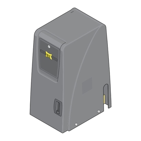
TMT Automation Clifford 400 User manual


2
UL Classication
Contents
1. Class I - Residential Vehicular Gate Operator
A vehicular gate operator (or system) intended for use in a home of one to four single
family dwellings, or garage or parking area associated therewith.
2. Class II - Commercial/General Access Vehicular Gate Operator
A vehicular gate operator (or system) intended for use in a commercial location or
building such as a multi-family housing unit (ve or more single family units, hotel,
garages, retail store or other building servicing the general public.
3. Class III - Industrial /Limited Access Vehicular Gate Operator
A vehicular gate operator (or system) intended for use in a commercial location or
building such as a multi-family housing unit (ve or more single family units, hotel,
garages, retail store or other building servicing the general public.
4. Class IV - Restricted Access Vehicular Gate Operator
A vehicular gate operator (or system) intended for use in a guarded industrial location
or building such as an airport security area or other restricted access location not
servicing the general public, in which unauthorized access is prevented via supervision
by security personnel.
Product Usage
This product meets all the safety requirements as set forth by the UL 325 standards.
This product is meant to be used as a Class I Residential Vehicular Gate Operator, and
is intended for this sole purpose.
------Important Instructions-------- 3
I. Before Installation 4
II. During Installation 5
III. After Installation 5
Warranty Information 6
Technical Specications 6
List of Parts 6
Tools Needed 7
Installation 8
I. Preparing the Gate 8
II. Pull to Open Installation 9
III. Push to Open Installation 13
IV. Control Box Installation
15
V. Connecting to the Control Box
15
VI. Connecting Batteries
16
VII. Connecting to an AC Adapter
18
VIII. Connecting the Solar Panels
18
IX. Setting Limit Switches 20
Control Board Setup 21
I. Push/Pull Switch
21
II. APP Override Switch 21
III. Stall Force Dial 21
IV. Autoclose Dial 22
Accessories 22
Wiring Accessories 22
Pairing Remotes 23
I. Using Factory Remotes 23
II. Unpairing Remotes 23
III. Connecting Other Controllers 24
IV. System Learning 24
V. Using the Remote 24
VI. Community Mode 24
VII. System Reset Via Remote 25
Troubleshooting 25
Manual Operation 27
I. To Disengage Motor Gear 27
II. To Remove the Gate Operator 27

3
Safety Overview
------Important Instructions--------
Thank you for choosing TMT Automation® Automatic Gate Opener System, a leader and
innovator in the eld of gate automation systems. This manual will guide you through the
steps of installation and maintenance. PLEASE READ AND FOLLOW THE STEPS CAREFULLY
TO REDUCE the risks of injury or death. Failure to meet the requirements set forth in the
instructions manual could result in result in damages for which the manufacturer cannot
be held responsible.
1. Keep in mind that the gate operator is just one component of the entire gate
operation system. To achieve optimal performance, be sure to properly install and
maintain all the components.
2. The gate operator is intended for use on vehicular gates only and not for pedestrian
gates. Unauthorized applications may induce safety risks.
3. The gate opener should be installed inside the fence and property line. Swing gates
must not open into areas where the public has access.
4. Do not let children operate or play with the gate controls.
5. Please keep people and objects clear of the gate its area of travel. No one should
cross the path of a moving gate.
6. Do not make any modifications to any components except to those that are
mentioned in this manual.
7. Make sure to comply with all local electrical and building regulations.
8. If you suspect that there is a problem with your gate opener, consult qualified
personnel before attempting to operate the gate.
9. While this system is equipped with safety measures designed to prevent injury and
damages to you and your vehicles, it is recommended that you purchase additional
devices such as photosensors to further enhance safety measures.

4
I. Before Installation
1. Please make sure your gate is in proper
working condition:
a. The gates should be level, firm and
able to swing freely in both directions.
b. The gate should be able to open and
close with minimal force applied.
c. The gate should be able to support
itself without wheels.
2. This gate opener can be used on metal,
chain link, tubular and wrought iron
gates. Use on wooden gates is not
recommended. Use discretion when
used on solid surface gates.
3. When planning the position of the
gates, leave ample room away from the
road to avoid traffic congestions. It is
recommended that you leave clear 10
feet in each direction of the operation
of the gate, if possible.
4. The entrapment zones are highlighted
in the diagram and are as follows:
a. The path of the gate. This may include
areas behind the driveways as the
gate can often have a swing angle of
over 90°.
b. Pinch points between the operator
and the gate.
c. Areas between the gate and the
column post.
STAY CLEAR AND BE AWARE OF THE
HIGHLIGHTED AREAS.
The terms gate opener and gate operator will be used interchangeably.

5
II. During Installation
III. After Installation
You can refer to the diagram below for a full system setup.
Note: Add additional components as desired.
Actual installation may differ from diagram.
1. Be aware of moving parts. Moving parts could pinch hands and ngers.
2. The gates should not open into public access areas to prevent unwanted collisions and
injuries.
3. Do not install the gate opener in an area that the public has access to; the gate openers
can be tampered with and cause security and other dangers.
4. Secure gate opener controls to prevent unauthorized users from gaining access.
5. For dual gate openers, be sure to leave room for a trench to run power lines.
6. When working with any electric components, be make sure the power is disconnected
and that your system is properly grounded to avoid risk of shock.
7. All power cables should be properly enclosed and insulated.
8. Other devices such as sensors can be added to provide additional protection against
entrapment.
1. Do not cross the path of a moving gate.
2. Attach warning signs to each side of the gate. The signs should be clearly legible.
3. Do not let children and unauthorized users operate the gate.
4. Keep pets and children away from the gates.
5. Periodically maintain the gates. Always turn OFF power before attempting to perform
any maintenance.
6. Apply properly lube on the actuator tube to make sure smooth operation. Silicon-based
lube is recommended.
7. Keep the key for manual release in an easily accessible location in case of an emergency.
8. Make sure you know how to use the manual release. If you still have doubts, refer to the
section in the back on how to operate the manual release.
9. In the event that you sell or lease your property, make sure to share this safety manual
with the new owners.
10. Periodically inspect if the wires are properly housed. Frayed or exposed wires can cause
serious risk of electrical res or shock.

6
List of Parts
Warranty Information
Our products are made to pass the most rigorous quality inspections. Our Limited Warranty
covers all defects in workmanship and material. Product registration is required, or warranty
is in effect starting from the date of purchase. TMT Automation will, at its discretion,
provide replacements for any defective parts within the terms of the warranty, free of any
charge.
To register, you can visit our website at www.tmtautomation.us.
Technical Specications
After opening the box, make sure to check for all the parts listed below. Please do not begin
installation until you have checked that all parts are present. If there are parts missing,
contact customer support and you will be provided with a replacement promptly.
Actual quantities can differ depending on the kit purchased.
Clifford 400
Gear Type Worm Gear
Power Supply 24V DC
Maximum Stroke Distance 23 in
Maximum Gate Length 20 ft
Maximum Gate Weight 1000 lbs
Operating Temperature -4°F ~122°F
Mounting Accessories

7
Tools Needed
Below is a list of tools recommended for installation. Please have them prepared before you
start your installation to save time.
Adjustable wrench
Wire Stripper Level
Drill Bits Saw Tape Measure
Hammer
Philips Screwdriver Flathead Screwdriver Pliers

8
1. The gate should swing freely, smoothly
and leveled.
2. The gate should be able to hang
without support from wheels. It is
recommended that gates weighing
above 250 lbs. use ball bearing hinges
designed to support such weights. The
hinges should be regularly maintained
and properly greased.
3. The gates should not swing uphill or
downhill while opening or closing. Any
incline in the process of gate operation
could affect the operator and may
require adjustments to the controller
variables.
4. There should be ample space on the
mounting column for the gate opener
to be mounted. The mounting brackets
need approximately 10 inches.
5. The gate openers should be mounted
near the center of the gate, otherwise
damage may be done to the gate.
The diagram below shows the optimal
position to mount the gate opener.
Top mounted and bottom mounted
congurations are not recommended.
6. It is recommended that the mounting
columns have the following specications:
a. Metal posts should be at least 3
inches in diameter, with at least a
foot with poured concrete set in the
ground.
b. Wooden posts should be at least 3
inches in diameter, with at least a
foot with poured concrete set in the
ground.
c. For masonry or brick columns, please
use the expansion bolts included.
Installation
Prior to installing the automatic gate operator, make sure of the following:
Center Mount
Top Mount
Bottom Mount
I. Preparing the Gate

9
7. Find a suitable location to mount the
control box and battery box. The control
box and battery box should be in range
of both gate operators. They should
also be at least a foot above the ground
to avoid splash and moisture damage.
8. If you live in a rural area where lightning
strikes may be of concern, make sure
to ground your gates. You can find
grounding systems (not included) in
most local hardware stores. These
systems will minimize the damage to
your gates and operator system.
9. If you wish to add other options such
as solar panels, electronic locks or other
sensors, make sure that your designated
mounting spot for the control box is
also within the range of these options.
10. Determine whether you wish to operate
your gate as a PUSH-to-OPEN or PULL-
to-OPEN gate. Consult the following
diagram for the two types of operations.
(Note that if you wish to operate the
gate as PUSH-to-OPEN, make sure that
the gate does not open into an area
which the public has access to and may
obstruct the movement of pedestrians
or trafc.)
Note: For your security, no matter the
direction in which your gate opens,
your gate opener should always be
installed on the inside of your property
to avoid any tampering and theft.
Push-to-Open gates have the actuator arm extend to open
the gates, often they open away from the property.
Pull-to-Open gates have the actuator arm retract to open
the gates, often they open towards the property.

10
1. Mark out the positions for the gate opener. Make sure that the mounting spots on the post
and the gate are leveled to the ground. You may want to use a Sharpie or tape to mark your
positions.
For dual opener setups, locate a place for the control box. The two operators come with
different length wires, so the operator with the shorter wire will have to be installed closer to
the control box.
Alternatively, you can also choose to use the square column mounting bracket. The square
mounting brackets can only be used for PULL-TO-OPEN applications, but the circular
mounting columns can be used for both.
2. Refer to the diagram below for the
proper positioning of the brackets.
• A is the vertical distance between the
hinge point and the mounting point
of the operator.
• B is the horizontal distance between
thehinge point and the operator
mounting point.
Choose the appropriate distances for
the desired opening angle.
3. Assemble the mounting brackets.
a. The mounting brackets should be
made up of two post brackets and
one pivot bracket in between.
b. Adjust the position of the pivot
bracket as needed.
c. Thread two bolt through the holes in
which the pivot brackets are properly
positioned.
d. Attach the nuts on the other side to
secure the bolts.
Refer to the diagram on the right
for assembly. You may want to leave
the nuts loose so that you can make
adjustments later.
II. Pull to Open Installation
CL''Centerline''

11
4. Use the clamps to notch the mounting brackets to the post. The center of the mounting
bracket should align with the center line as labelled in the diagram in Step 1. Mark the
positions where the mounting brackets should latch on to the post.
5. Release the clutch of the gate operator as shown below. When your opener is fully released,
you should be able to move the actuator arm with minimal force.
6. Use the gate opener to help you adjust the angle of the mounting bracket. When the gate
opener is fully extended, the gate should be in the closed position. You may want to adjust
the clutch release to fully extend the gate opener arm. Adjust the angle of the mounting
bracket accordingly. (Refer to the diagram below.) Make sure that the angle of operation is
not obstructed.

12
7. After you have set the angle, insert the bolt and washer to set the angle of the mounting
bracket.
9. Repeat the process for the mounting brackets on the gate. This bracket only needs two bolts.
Alternatively, if you have a tubular gate, you can choose to use U-shaped mounting brackets
which will allow you to not drill holes.
10. With the clutch of the gate opener released, try to open and close the gate to see if
operation is smooth. Once you are satised with the position, tighten all nuts and bolts.
Note: Before the gate system will be able to work, you need to complete system learning.
11. Repeat the process for the other gate leaf.
8. Once the positions of the mounting brackets are measured and checked, you can now drill
holes to fasten the brackets. You may want to keep the clamps to hold the post mounting
brackets in place, and slowly drill one hole at a time. After drilling the hole, insert the bolt
through it to make sure that the holes are large enough and properly aligned. Once all holes
are drilled and the bolts threaded through, tighten the nuts to secure the mounting bracket.
Refer to the diagram below.

13
3. Refer to the diagram below for the proper
positioning of the brackets.
• A is the vertical distance between the
hinge point and the mounting point of the
operator.
• B is the horizontal distance between the
hinge point and the operator mounting
point.
Choose the appropriate distances for the
desired opening angle.
1. To have a push to open gate, make sure that you will not be at risk of colliding into
pedestrians or oncoming trafc.
2. Mark out the positions for the gate opener. Make sure that the mounting spots on the post
and the gate are leveled to the ground. You may want to use a Sharpie or tape to mark your
positions.
III. PUSH to OPEN Installation
CL''Centerline''
4. Assemble the mounting brackets.
a. The mounting brackets should be
made up of two post brackets and
one pivot bracket in between.
b. Adjust the position of the pivot
bracket as needed.
c. Thread two bolt through the holes in
which the pivot brackets are properly
positioned.
d. Attach the nuts on the other side to
secure the bolts.
Refer to the diagram on the right
for assembly. You may want to leave
the nuts loose so that you can make
adjustments later.
For dual opener setups, locate a place for the control box. The two operators come with
different length wires, so the operator with the shorter wire will have to be installed closer to
the control box.

14
5. Use the clamps to notch the mounting brackets to the post. The center of the mounting
bracket should align with the center line as labelled in the diagram in Step 2. Mark the
positions where the mounting brackets should latch on to the post.
6. Use the gate opener to help you adjust the angle of the mounting bracket. When the gate
opener is fully retracted, the gate should be in the closed position. You may want to adjust
the clutch release to allow for free movement of the gate opener arm. At no point should the
bracket or gate opener be trapped by the posts. If this situation happens, adjust the pivot
bracket length and the angle of the mounting bracket.
7. Secure the mounting brackets onto the post. Then secure the gate opener onto the
mounting bracket.
8. Extend the gate opener fully and push the gate to the open position. Secure the gate opener
to the gate.
9. With the clutch released, try opening and closing the gate to make sure that it is working
smoothly. When you are satised tighten all nuts and bolts.
10. With the clutch of the gate opener released, try to open and close the gate to see if
operation is smooth. Once you are satisfied with the position, tighten all nuts and bolts.
Note: Before the gate system will be able to work, you need to complete system learning.
11. Repeat the process for the other gate leaf.

15
1. After determining the position of the control box, you may want to use the clamps to
mark up the position of the holes and help you secure the box. Note that the control box
should be at least one foot from the ground and within ve feet of at least one of the gate
operators.
2. Drill holes as necessary at the bottom of the control box. The holes should be large enough
to feed the wires through.
3. Drill four holes into the back of the control box and through the mounting posts where you
will be securing the control box to.
4. Make sure that the orientation and the position of the box is correct, then tighten the screws
to secure the control box.
5. Check that the control box power is switched to the OFF position before attempting to
connect other components.
1. Make sure that power is not connected and is switched OFF.
2. Loosen the sealing nut at the bottom of the control box, and thread the wires of one gate
operator (there should be ve wires) through the strain relief, then tighten the sealing nut
until the cable locks in place.
3. The wires leading from the operator should be connected to the terminal blocks by matching
the colors as shown below. The bundle of 2 wires contains a white and a yellow wire that
should be connected to the M+ and M- terminals (they can be labelled as M1+/M1- or
M2+/M2-).
IV. Control Box Installation
V. Connecting to Gate Opener to Control Box
M+ M- LMT 1 LMT 2 GND
Yellow White Red Green Black

16
4. There should not be any exposed strands of wires, and the screws should screw into wire and
not the wire insulation.
5. If you have more than one opener, repeat the process for the other gate opener. Note that
for the second set of openers, you should connect to a terminal block that is different from
the one that the rst opener is connected to.
NOTE: This system requires batteries to be connected
to work.
1. Batteries are not included in this kit. The system
should be powered by two 12 V batteries. We
recommend 12 V 5 Ah batteries as the battery box is
designed with their dimensions in mind.
2. Find a position close to control box and mount the
battery box. The battery box should also be at least
one foot above the ground, to avoid water and dirt
damage.
3. Before attempting to connect batteries to the control
board, make sure the power switch for the control
board is in the OFF position.
4. First connect each of the batteries to the battery
harness included in the battery box.
The batteries should be in series, connect the red
wire to the positive (+) terminal of Battery 1. This
should be connected rst. Connect the black wire to
the negative (-) terminal of Battery 2. Then connect
the negative (-) terminal of Battery 1 to the positive
(+) terminal of Battery 2.
VI. Connecting Batteries as a Power Supply

17
5. The negative terminal of the battery should be connected to the black wire, and the black
wire should be connected to the slot labelled BAT-. It is recommended that you connect the
negative terminals before the positive terminals.
6. The positive terminal of the battery should be connected to the red wire, and the red wire
should be connected to the terminal labelled BAT+.
7. When the batteries are properly connected, the BATTERY LED should light up. If the BATTERY
LED is flashing, it means that the batteries do not have enough voltage and need to be
charged.

18
1. Make sure the power switch for the control
board is in the OFF position. DO NOT connect
the AC adapter to a power source until you have
nished wiring the adapter to the control board.
The AC Adapter unit consists of an AC
transformer block, an adapter wire to the
control board and an adapter wire to the outlet.
Assemble the units as shown below.
2. Connect the two wires to the two terminals
marked by Power+ and Power-. Each of the
wires should go in a separate terminal.
3. After connecting the wires to the terminals,
tighten the screws. There should not be any
exposed strands of wires.
4. If the AC adapter is connected properly, the
POWER LED will light up after the control board
is switched ON and power is connected.
VII. Connecting the Control Box to an AC Adapter
1. Find a suitable position to mount the solar panels near the control board.
2. To install the solar panels, secure the U-shaped mounting brackets to the back of the solar
panels, and tighten it against the curved pipe. The 2 pieces of solar panel should t on the
long end of the curved pipe, and the shorter end should be attached to the mounting post/
column.
VIII. Connecting the Solar Panels

19
6. If the solar panels are connected properly, you should see the POWER LED flash for five
seconds before returning to its prior status.
4. The solar panels should be connected in parallel. All the positive (+) terminals should be
connected to each other, and all the negative (-) terminals should be connected to each
other.
5. Connect the wires into the terminal block labelled power. The red wire leading from the solar
panel should be connected to the terminal marked Power+ and the black wire leading from
the solar panel should be connected to the terminal marked Power-.
3. The mounting brackets are equipped with a notch that can t into the holes on the curved
pipe, as seen below. If you want to change the orientation of the panels, drill a hole through
the mounting brackets and pipe and secure with a screw.
Make sure the power switch for the control board is in the OFF position before attempting to
connect the solar panels.

20
1. To set limit switches, rst remove the screws at the end of the operator.
2. After removing the screws, you can remove the top cover. You should be able to see the
actuator inside and the limit switches that run along rails at the top.
Unscrew the screws on the limit switches as shown below, this will allow you to move the
limit switches.
3. Move the two limit switches to the desired position. These positions would be where the
operator starts to slow down. You would want to have the limit switches be in a position
where they would initiate before the operator nishes its full length of travel.
4. After moving the limit switches to the desired positions, put the screws back on the limit
switches and put back the top cover along with the screws.
IX. Setting Limit Switches
Table of contents
Other TMT Automation Gate Opener manuals
Popular Gate Opener manuals by other brands

ALLOMATIC
ALLOMATIC SL-100AC manual
GiBiDi
GiBiDi MODO12 Instructions for installations
G-Force
G-Force AG 5 DC2 Installation and setup instructions

HySecurity
HySecurity Nice 3501 installation manual

Keyautomation
Keyautomation STAR3024 Instructions and warnings for installation and use

Elite
Elite CSW200UL instruction manual
