TOA-DKK OBM-100H User manual

Please keep this instruction manual close at hand of the persons who are in charge of
the operation of this product.
Before operating this product, please read this instruction manual carefully for its
correct handling.
DISSOLVED OXYGEN
ANALYZER/TRANSMITTER
MODEL OBM-100H
No. OBM-IB45802E

Model: OBM-100H Introduction
-
1
-
Introduction
(a)Thank you for your purchase of our product. The Model: OBM-100H dissolved oxygent
Analyzer/Transmitter (hereafter called the transmitter or the product) is an indicating transmitter in
a measurement system to measure dissolved oxygen (DO) in solution and is installed in various
processes.
When extension cable is used
Extension cable
Connector box
Analyzer/Transmitter
Model OBM-100H Recorder, etc.
Sensor
(Model OC-64, BOC-64)
Example of a Measurment System
(b)The entire measuring range of DO is 0.00μg/L to 20.00mg/L. Any measuring range can be selected
within this range but normally the measuring range is preset according to the ordered
specifications. The power source voltage is 90 to 26VAC. For other specifications, refer to 6.1
“Specifications”
(c)The following screens are provided. Among them, note, however, that transmission output
accommodates to DO measured values only.
DO Measured Value Screen (unit: μg/L)······Dissolved oxygen concentration in water
O2Measured Value Screen (unit: %)············Oxygen (O2) concentration in the air
SAT Measured Value Screen (unit: %) ·········Saturation ratio of dissolved oxygen in water
(hereafter called SAT)
Atmospheric pressure measurement (unit: hPa) screen····· Atmospheric pressure
Temperature Display Screen (°C) ···································· Temperature in water
(d)Measurement with automatic temperature compensation can be performed if a DO electrode of
DKK-TOA such as Model 7561L, 7562L, 7563L, 7564L, 7535L or 7538L is combined with the
transmitter.
(e)DO measured value is affected by the atmospheric pressure. However, a pressure sensor is built in
the transmitter and the effect of the atmospheric pressure will be automatically corrected.
(f) This manual mainly describes the transmitter. For the DO electrode or sensor combined with the
transmitter, refer to the instruction manual attached to the DO electrode or sensor.
(g)There is a possibility that the product indicates or outputs an erroneous measured value by the
following causes. Prepare a backup system so that no damage occurs to the related facilities even
in the case like these.
•Any problem of the product such as deterioration or damage of the detecting section or
inappropriate insulation of cables.
•Improper setting of operating conditions or calibration operation.

Model: OBM-100H Introduction
-
2
-
•Electrical interference such as noise in the vicinity or improper grounding.
•Other unpredictable phenomena
(h)Since important items are described in “Safety Information”, read the contents carefully.
(i) The product should be handled by persons who have received proper training. In addition, for
technical services such as repairs, ask a specialist to do who is qualified for the technical
certification system in our company or a person who has technical skills equivalent to that
certification system.

Model: OBM-100H Safety Information
-
3
-
Safety Information
(1) Meaning of markings
Meaning of symbols such as the ones used in notations of warning in the instruction manual is
described below. In addition, the alert symbol ( : General caution symbol) used on a product label,
etc. is meant to notify the existence of hazard/loss and it also means “Refer to the Instruction
Manual”.
:
Indicates the degree of hazard which can lead to death or serious injury if you fail to operate the
product properly.
Serious injury means an injury such as loss of sight, burns (high temperature or low temperature),
electric shock, bone fracture and poisoning, and the aftereffects of the injury remains or the injury
requires hospitalization or long periods of outpatient treatment.
:
Indicates the degree of hazard/loss which can result in minor injury or property damage if you fail to
operate the product properly.
Minor injury means an injury not requiring hospitalization or long periods of outpatient treatment.
Property damage refers to damage that affects property around the product such as equipment and
buildings (wide-ranging damage).
【IMPORTANT】: Indicates important matters such as to prevent damage to the product main body,
prevent data destruction, prevent wasting time, and maintain performance.
〔NOTE〕 : Indicates comments, reasons, background information, a case example and other
items to help the reader understand the meaning.
: Indicates reference items.
①, ②, ③: Indicates item numbers such as the ones used in operations.
(2) Safety compliance items
Hazardous Gasses
Do no use the product in an area where explosive gas, flammable gas exists. Using
the product in any of these areas can cause explosion or fire.
Electric Shock
Do not touch the terminal board while power is applied. Touching the terminals may
cause electric shock.
The ground terminal must be grounded. If the terminal is not grounded and a problem
occurs in the power supply system, electric shock may result.

Model: OBM-100H Safety Information
-
4
-
Disassembly and Modification
Do not disassemble or modify the sections of the product that are not described in
the instruction manual. The product can be damaged.
Warning Label Lost
If any warning label affixed to this product becomes too difficult to read or lost,
please order a new one through your local sales agent or our sales office and affix it
to its original position.
Disposal
In case you dispose of this product or any part of this product, handle it as industrial
waste as specified by law.
(3) Notes on use of the instruction manual
Important items such as “Safety compliance items” are described in this manual. Handle the manual
as follows:
(a)The instruction manual is required not only at the start of operation but also required when
maintenance is performed or in case a failure occurs. Please keep the manual at hand all the time so
that the operator who actually operates the product can read the manual at any time.
(b)If the manual is lost or too smeared to read, please order a new copy through your local sales agent
or directly from our sales office.
(c)Some of the diagrams used in the manual or on product labels may be modified with part of their
shapes or displays omitted or they may be described in abstract form. In addition, numbers etc.
shown on the screen example are just examples for such cases.
(d)The contents of the manual may be changed without prior notice for reasons such as to improve
performance.
(e)Intellectual property right of the manual belongs to DKK-TOA. All or part of the manual must not
be reproduced without permission.

Model: OBM-100H Product Warranty
-
5
-
Product Warranty
(1) Scope
DKK-TOA Corporation (hereafter referred to as “our company”) warrants that if a product
manufactured by our company proves to be defective in material or workmanship, our company will
provide the customer, without charge, the parts necessary to remedy any such defect for a period of
one (1) year.
(a) The warranty period shall commence on the date the product is purchased by the original retail
consumer. When the delivery date is unavailable, the warranty period shall be 24 months from the
first day of the month following the month and year of manufacture indicated on the product
nameplate.
(b)This warranty is valid unless otherwise contracted.
(c) In case of failure or damage outside the scope of this warranty and such failure is attributable to
our company, legal rights are not restricted regardless of warranty period.
(2) Out of scope
This warranty does not apply to the following items. Repair shall be available for a fee.
(a) Direct or indirect failure or damage due to application outside the specifications of the product or
an operating method exceeding the range described in the instruction manual.
(b)Direct or indirect failure or damage due to natural disasters, such as earthquake, wind and flood
damage and lightning, accident, fire, abnormal voltage, salt damage, or gas damage.
(c) Failure or damage due to inappropriate repair or modification by the customer.
(d)Failure or damage due to transportation or relocation by the customer or falling that occurred after
acceptance of the product.
(e) Electrodes and consumables (Warranty period for each part has priority when the period is shorter
than that for the main unit of the product. If the customer requires any part after more than six
months from the date of manufacture, consult our company.)
(f) Failure or damage due to use of consumables, parts, and software manufactured by other
companies.
(g)Failure or damage due to a connection to a device manufactured by another company.
(h)Loss of data, settings information, programs, and software saved in the product by the customer.
(i) When our product is combined with a product specified by the customer and manufactured by
another company or when our product incorporates such a product, the warranty from our
company applies only to our product. The product manufactured by another company shall be
provided with a warranty according to the warranty document (*1) prepared by the other company.
(j) Defect or damage due to failure to follow the maintenance procedures specified by our company in
the instruction manual.
(k)The product with no nameplate of our company unless evidence of delivery from our company
exists.
(3) Others
(a) Maintenance parts (*2) for the product can normally be supplied for five years (*3) after
manufacturing or sales of the product are discontinued.
(b)Engineers from our company shall determine the cause of failure or damage.
(c) Request repairs from our sales section.
*1: Store the warranty document for a product manufactured by another company.
*2: The maintenance parts mean those necessary for maintaining operation of the product.
*3: If a part cannot be procured and no alternative is found, this period may be shorter.

Model: OBM-100H Reading Guide
-
6
-
Reading Guide
Refer to the necessary sections of this instruction manual depending on your purposes such as
understanding the outline of this product or starting the product as shown below. The numbers in
circles indicate sections to be referred to in sequential order.
Purpose
Section
Perform
respective
operations
Maintenance
and inspection,
and
troubleshooting
Understand
the outline of
this product
Check
installation,
piping and
wiring
Start
(start-up)
2. Transmitter Operation
and Calibration
1. Names of Each Part
5. Troubleshooting
4. Maintenance
3. Modes of Operations
8. Installation
7. RS-232C Connector
6. Specifications and
Description
Safety Information
Introduction

Model: OBM-100H Table of Contents
-
7
-
Table of Contents
●Introduction················································································································1
●Safety Information·······························································································3
(1) Meaning of markings ⋅⋅⋅⋅ 3
(2) Safety compliance items ⋅⋅⋅⋅ 3
(3) Notes on use of the instruction manual ⋅⋅⋅⋅ 4
●Product Warranty·································································································5
●Reading Guide ·······································································································6
1. Names of Each Part····················································································10
(1) Names of main components ⋅⋅⋅⋅ 10
(2) Key and indicating functions ⋅⋅⋅⋅ 11
(3) Operation screen map ⋅⋅⋅⋅ 13
2. Transmitter Operation and pH Calibration·····························15
2.1 Operation Start Procedure·····················································································15
2.2 Calibration··············································································································18
(1) Zero calibration using a solution ⋅⋅⋅⋅ 18
(2) Electrical zero calibration ⋅⋅⋅⋅ 21
(3) Span calibration using air ⋅⋅⋅⋅ 22
(4) Span calibration using air saturated water ⋅⋅⋅⋅ 23
(5) Indicated value at the time of span calibration ⋅⋅⋅⋅ 25
2.3 Stopping the Operation··························································································26
(1) Stopping the operation for a short period of time ⋅⋅⋅⋅ 26
(2) Stopping the operation for a long period of time ⋅⋅⋅⋅ 26
3. Modes of Operations··················································································28
3.1 Modes and Switching Method···············································································28
(1) Checking the current mode ⋅⋅⋅⋅ 28
(2) Switching between modes ⋅⋅⋅⋅ 28
3.2 Measurement Mode Operation··············································································29
(1) Screen group of measurement mode ⋅⋅⋅⋅ 29
(2) Selecting the measured value screen ⋅⋅⋅⋅ 30
(3) Alarm check ⋅⋅⋅⋅ 31
(4) Checking the measuring range ⋅⋅⋅⋅ 33
(5) Checking other setting values ⋅⋅⋅⋅ 33
3.3 Setting Mode Operation·························································································36
(1) Setting mode screen groups ⋅⋅⋅⋅ 36
(2) Alarm setting ⋅⋅⋅⋅ 37

Model: OBM-100H Table of Contents
-
8
-
(3) Description of calibration related screens ⋅⋅⋅⋅ 41
(4) DO value adjustment setting ⋅⋅⋅⋅ 42
(5) Temperature shift setting ⋅⋅⋅⋅ 43
(6) Setting the atmospheric pressure shift ⋅⋅⋅⋅ 44
(7) Setting the measuring range ⋅⋅⋅⋅ 45
(8) Setting the zero calibration signal value and span calibration signal value ⋅⋅⋅⋅ 47
(9) Burnout setting ⋅⋅⋅⋅ 48
(10) Setting mode transmission output type setting ⋅⋅⋅⋅ 49
(11) Setting the response speed ⋅⋅⋅⋅ 50
(12) Setting the stability check on/off for calibration ⋅⋅⋅⋅ 51
(13) Setting the impress voltage ⋅⋅⋅⋅ 52
(14) Setting the manual temperature compensation ⋅⋅⋅⋅ 53
(15) Atmospheric pressure correction setting ⋅⋅⋅⋅ 54
(16) Setting the measurement mode auto return ⋅⋅⋅⋅ 55
3.4 Transmission Adjustment Mode Operation···························································56
4. Maintenance·······································································································57
4.1 Maintenance List····································································································57
4.2 Spare Parts·············································································································58
4.3 Operation Check Using Equivalent Input ·····························································58
4.4 Checking the Insulation Resistance of Extension cable······································62
5. Troubleshooting·······························································································64
5.1 Error Message········································································································64
(1) Error messages for calibration and necessary actions ⋅⋅⋅⋅ 64
(2) Other error messages and necessary actions ⋅⋅⋅⋅ 66
5.2 Troubleshooting Flowchart····················································································68
5.3 Measures Against Noise························································································69
6. Specifications and Description ·························································70
6.1 Specifications·········································································································70
6.2 Factors that Influence the Measurement······························································72
7. RS-232C Connector····················································································74
(1) RS-232C connector function ⋅⋅⋅⋅ 74
(2) Pin arrangement and communication cable ⋅⋅⋅⋅ 74
(3) Wiring ⋅⋅⋅⋅ 75
(4) Command format ⋅⋅⋅⋅ 76
8. Installation············································································································77
8.1 Transmitter Mounting·····························································································77
(1) Installation location ⋅⋅⋅⋅ 77
(2) Dimensions and mounting example ⋅⋅⋅⋅ 77
8.2 Wire Connection·····································································································79

Model: OBM-100H Table of Contents
-
9
-
(1) Connection diagram ⋅⋅⋅⋅ 79
(2) Electrode signal input terminals ⋅⋅⋅⋅ 80
(3) Transmission output terminal ⋅⋅⋅⋅ 80
(4) Power input terminals ⋅⋅⋅⋅ 80
(5) Ground terminal ⋅⋅⋅⋅ 81
(6) Alarm signal output terminals ⋅⋅⋅⋅ 81
(7) Maintenance-in-progress signal output terminals ⋅⋅⋅⋅ 82
(8) Error signal output terminals ⋅⋅⋅⋅ 82
(9) Wire connection to terminal board ⋅⋅⋅⋅ 83
8.3 Extension Cable and Connector Box····································································84
(1) Extension cable installation ⋅⋅⋅⋅ 84
(2) Mounting the connector box ⋅⋅⋅⋅ 85
(3) Wire connection for electrode lead wires ⋅⋅⋅⋅ 85
(4) Wire connection for extension cable ⋅⋅⋅⋅ 87
(5) Ground wire connection for connector box ⋅⋅⋅⋅ 87
(6) Wiring to the connector box using conduit pipe ⋅⋅⋅⋅ 88
(Last page ⋅⋅⋅⋅ 88)

Model: OBM-100H 1. Names of Each Part
-
10
-
1. Names of Each Part
(1) Names of main components
Terminal board cover
Control panel
Fixture
Stand-by indicator
Range indicator
OUT indicator
Alarm indicator
Alarm key
Stand-by/Meas key
CAL key Up key Down key Data key
Wait indicator
Sub display
CAL indicator
Enter key
DISP key
Range key
OUT key
Temperature
indicator
% unit mark
Main display (when all of the lights are indicated)
When RS-232C connector (option) is
used, the shape of the terminal block
cover differs partly.
mg/L unit mark
g/L unit mark
hPa unit mark
Names of Main Components
Model: OBM-100H 1. Names of Each Part
-
11
-
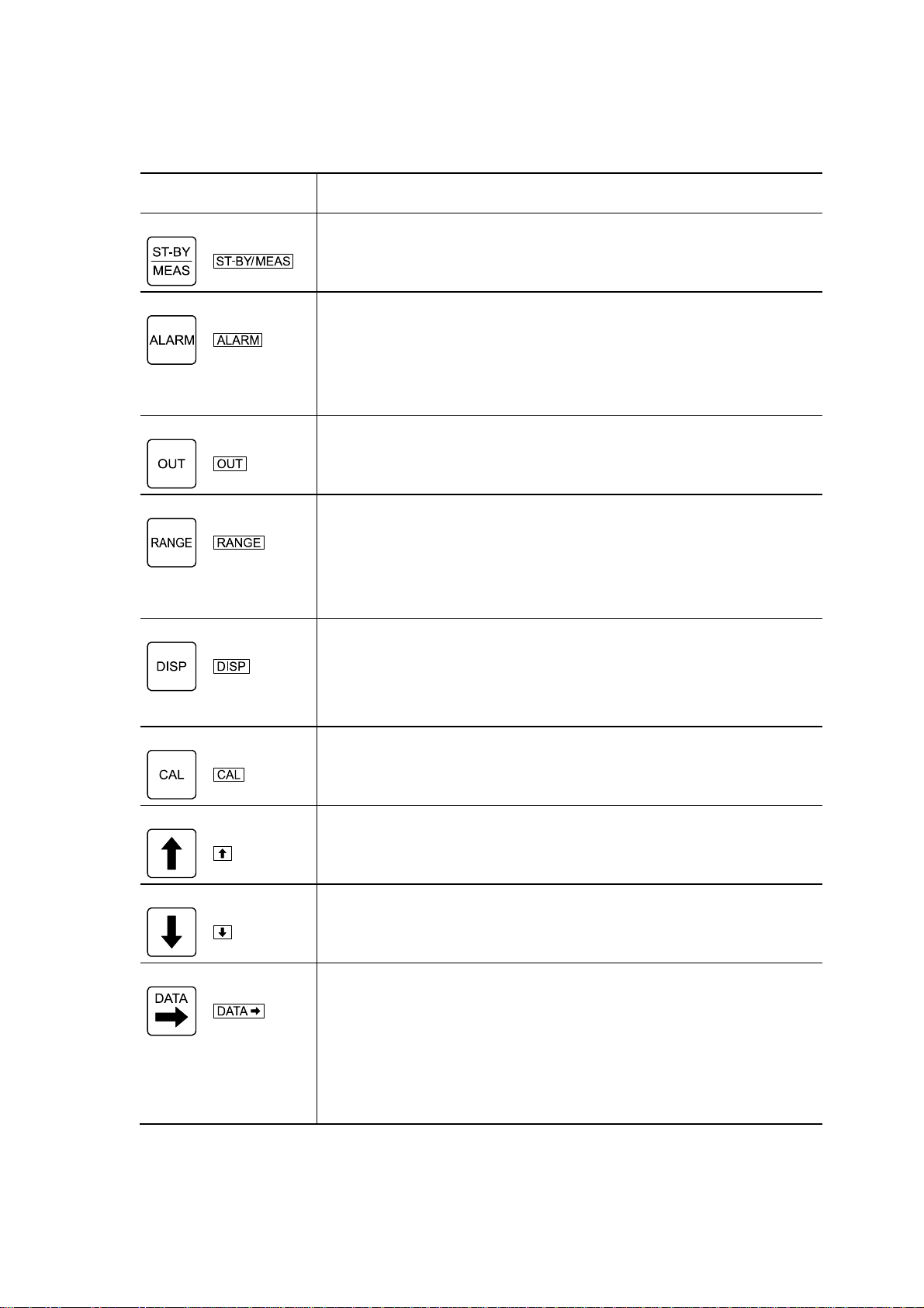
(2) Key and indicating functions
Key function
Operation key
(notation in the text) Function
Stand-by key
( )
•When pressed longer (3 seconds or more) in the measurement mode, the Initial
Screen of the setting mode appears
•When pressed longer in the setting mode, the screen returns to “DO measured
value (DO)” screen.
Alarm key
( )
•When pressed while a screen of the measured value screen group is displayed,
the screen goes to the alarm display screen group and when this key is pressed
repeatedly, the screen changes sequentially within this group and finally the
screen returns to “DO measured value (DO)” screen.
•When pressed longer while the Initial Screen of the setting mode is displayed,
“Alarm 1 on/off ” screen, the initial screen of the alarm setting screen group
appears.
Out key
( )
•When pressed longer in the measurement mode, the transmitter goes to the
transmission adjustment mode and when this key is pressed longer in the
transmission adjustment mode, the screen returns to “DO measured value (DO)”
screen.
Range key
( )
•When pressed while a screen of the measured value screen group is displayed,
the screen goes to the measuring range check screen group and when this key is
pressed repeatedly, the screen changes sequentially within this group and finally
the screen returns to “DO measured value (DO)” screen.
•When pressed longer while “Setting mode initial” screen is displayed, the “DO
measuring range unit setting (UNIT)” screen of the measuring range setting
screen group appears.
DISP key
( )
•Pressing this key repeatedly in the measured value screen group changes the
screen sequentially within the group and finally the screen returns to “DO
measured value (DO)” screen.
•When pressed longer in the “Setting Mode Initial” screen, the “DO Value Adjust
On/Off” (D.ADJ) screen, the initial screen of the adjustment screen group,
appears.
CAL key
( )
•When pressed longer in the “Setting mode Initial” screen, the “Calibration
select” screen (AUTO, etc.), the initial screen of the calibration screen group,
appears.
Up key
( )
•This key is used to increase the number to set or change the symbol in the setting
mode or in the transmission adjustment mode.
Down key
( )
•This key is used to decrease the number to set or change the symbol in the setting
mode or in the transmission adjustment mode.
Data key
( )
•When pressed while a screen of the measured value screen group is displayed,
the screen goes to the other setting value display screen group and when this key
is pressed repeatedly, the screen changes sequentially within this group and
finally the screen returns to “DO measured value (DO)” screen.
•When pressed longer while the Initial Screen of the setting mode is displayed,
the “Zero calibration signal value setting (ZERO)” screen, the initial screen of
the other setting screen group, appears.
•When pressed in the setting mode or in the transmission adjustment mode, the
digit of the number to set moves to the right by one.
(To be continued)

Model: OBM-100H 1. Names of Each Part
-
12
-
(Continued from previous page)
Operation key
(notation in the text) Function
Enter key
( )
•This key is used to change the screen in the setting mode or in the transmission
adjustment mode. In addition, this key is used to confirm the entered number or
symbol and change the screen to the next one at the same time.
Indicating Function
Indicating function Function
Main display
•4-digit number or 4 alphabetic characters can be displayed. The minus symbol can
be displayed on the left.
•The measured value is mainly displayed in the measurement mode, and setting
values and selected items, etc. are displayed in the setting mode and in the
transmission adjustment mode.
Sub display
•4-digit number or 4 alphabetic characters can be displayed. The minus symbol can
be displayed on the left.
•Temperature value is mainly displayed in the measurement mode, and setting
values and selected items, etc. are displayed in the setting mode and in the
transmission adjustment mode.
Unit mark
•This mark indicates the unit shown on the main display.
Temperature indicator
°
C
•This indicates the unit for the number shown on the sub display.
Stand-by indicator
ST-BY
•This indicates the transmitter is not in the normal measurement state.
•This indicator when lit indicates the transmitter is currently in the setting mode or
in the transmission adjustment mode. Blinking state indicates the setting is
currently being changed.
CAL indicator
CAL
•When this indicator is lit, it indicates that the transmitter is in the calibration
screen group of the setting mode.
•When this indicator is blinking, it indicates that the transmitter is in the process of
calibration or in the transmission adjustment mode.
Range indicator
RANGE
•This indicates that the current main display is related to the measuring range.
OUT indicator
OUT
•This indicates the current screen is related to the transmission output.
Alarm indicators
ALARM1
ALARM 2
•This indicates the current screen is related to the alarm output.
•ALARM1 indicates the condition of Alarm 1 and ALARM2 indicates that of
Alarm 2.
Wait indicator
WAIT
•This indicates the stability check for calibration is in progress.
Model: OBM-100H 1. Names of Each Part
-
13
-
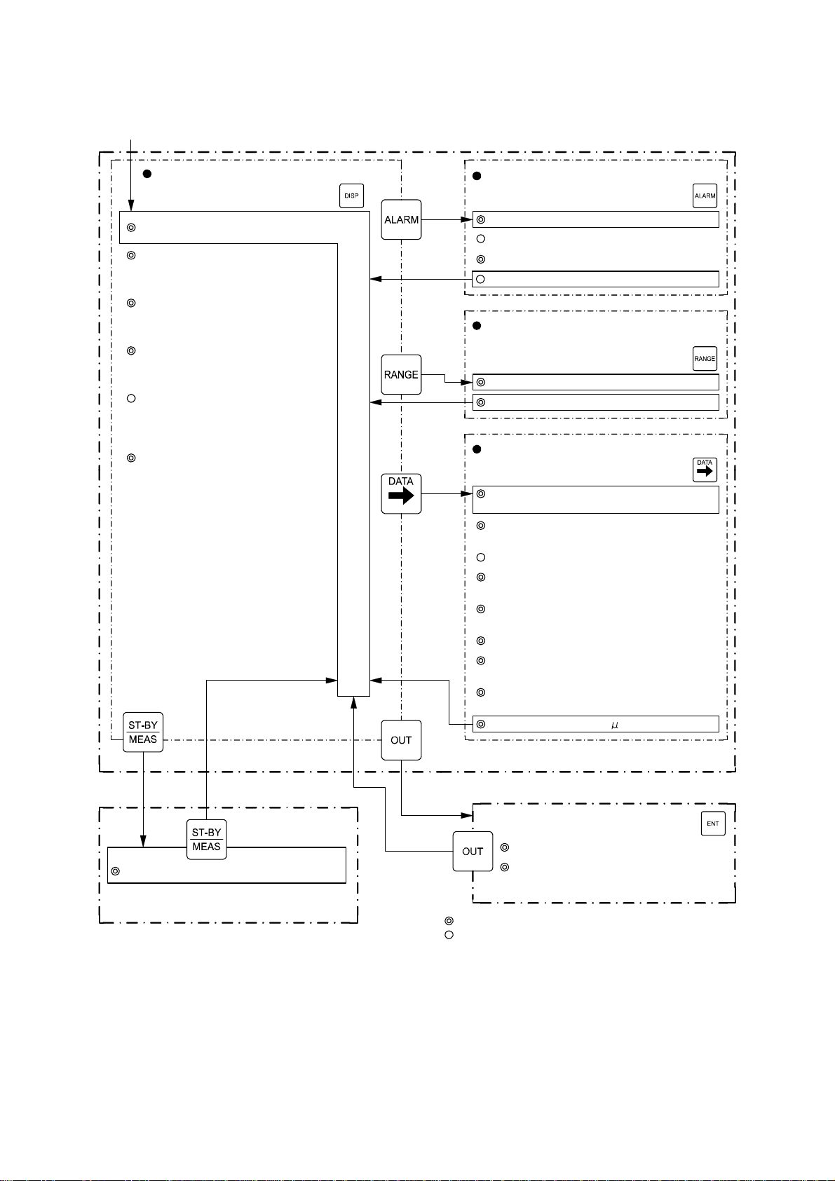
(3) Operation screen map
Power turned on (ON) [Measurement mode]
(To switch screen: )(To switch screen: )
(To switch screen: )
(To switch screen: )
Measured value screen group
DO measured value (DO) screen
O2measured value (O2) screen
(Returns to “DO measured value”
screen in 20 seconds.)
SAT measured value (SAT) screen
Temperture measured value screen
DO/Temperature screen
(Temperature measured value)
(Returns to “DO measured value”
screen in 20 seconds.)
(Returns to “DO measured value”
screen in 20 seconds.)
Alarm check screen group
Alarm 1 set point check (-/L/H) screen
Alarm 1 dead band check (BAND) screen
Alarm 2 set point check (-/L/H) screen
Alarm 2 dead band check (BAND) screen
Measuring range check screen group
(transmission output range)
DO measuring range low limit (4mA) screen
DO measuring range high limit (20mA) screen
Other setting values check screen group
Zero calibration signal value check (ZERO)
screen
Span calibration signal value check (SPAN)
screen
Burnout check (B.OUT) screen
Setting mode transmission output type check
(S.OUT/12.00 etc.) screen
Transmission response speed check (RESP)
screen
Calibration stability check on/off (WAIT) screen
Impress voltage check (V.SET) screen
(for technical services)
Measurement mode auto return check (M.RET)
screen
Electrode current check ( A) screen
(To switch screen: )
Press longer
Press longer
Press longer
Press
longer
[Setting mode]
Setting mode initial screen
(Refer to <Operation Screen of Setting Mode>
on next page.)
[Transmission adjustment mode]
Transmission 4mA adjust screen
Transmission 20mA adjust screen
(For technical services)
Press longer: Press the key for 3 seconds or more.
: Screens that appear always
: Screens that appear when necessary setting is made.
Atmospheric pressure measurement
screen
(Returns to “DO measured value”
screen in 20 seconds.)
Operation Screen Map (1/2)

Model: OBM-100H 1. Names of Each Part
-
14
-
[ Setting mode ]
(To switch screen: )
Press longer
Press longer: Press the key for 3 seconds or more.
: Screens that appear always
: Screens that appear when necessary setting is made. Press longer: Returns to the “DO measured value” screen
of measurement mode.
Setting mode initial screen
Alarm setting screen group
Alarm 1 on/off setting screen
Alarm 1 high/low setting screen
Alarm 1 set point setting (L/H) screen
Alarm 1 dead band setting (BAND) screen
Alarm 2 on/off setting screen
Alarm 2 high/low setting screen
Alarm 2 set point setting (L/H) screen
Alarm 2 dead band setting (BAND) screen
(Pressing longer
not required)
(To switch screen: )
Calibration screen group
Calibration select (AUTO/Z.ELC/Z.SLU/SPAN etc.) screen
Calibration (AUTO/Z.ELC/Z.SLU/SPAN etc.) screen
(To switch screen: )
Press longer
Other setting screens group
Zero calibration signal value setting (ZERO) screen
Span calibration signal value setting (SPAN) screen
Burnout setting (B.OUT) screen
Setting mode transmission output type setting (S.OUT) screen
Dummy transmission value (dU.mA) screen
Transmission response speed setting (RESP) screen
Calibration stability check on/off setting (WAIT) screen
Impress voltage setting (V.SET) screen
Manual temperature compensation on/off setting (M.TMP) screen
(To switch screen: )
Press longer
Measuring range setting screen group
DO Measuring range unit setting (UNIT) screen
DO Measuring range low limit setting (4mA) screen
DO Measuring range high limit setting (20mA) screen
(To switch screen: )
Press longer
Adjust / Shift setting screen group
DO value adjust on/off setting (D.ADJ) screen
DO value adjust setting (D.ADJ) screen
Temperature shift on/off setting (SHFT) screen
Atmospheric pressure shift value setting (P.SET) screen
Temperature shift value setting (SHFT) screen
Atmospheric pressure shift on/off setting (P.SET) screen
Measurement mode auto return setting (M.RET) screen
Manual temperature compensation value setting (M.TMP) screen
Atmospheric pressure correction on/off setting (ATM.P) screen
Operation Screen Map (2/2)

Model: OBM-100H 2.1 Operation Start Procedure
-
15
-
2. Transmitter Operation and pH Calibration
2.1 Operation Start Procedure
Follow the procedure below for operation. The measurement system including the transmitter goes
into normal operating state.
①Check the installation condition. ⋅⋅⋅⋅⋅⋅ Check that necessary installation work is completed,
which is described in 8. “Installation” (mounting and wire connection) and the installation items
described in the instruction manual provided for the sensor.
②Introduce sample water. ⋅⋅⋅⋅⋅⋅ Open the sample supply valve to let the sample water flow into the
sensor and adjust the flow rate of the sample using the control valve provided near the entry point
of the sensor.
Flow rate of sample: Constant flow rate of 100 to 500mL/min.
If a flowmeter of 20 to 200 mL/min (option) is used, set the flow rate to 100mL/min. If a
flowmeter of 100 to 1000mL/min (option) is used, set the flow rate to 100 to 500mL/min.
Sensor
Flowmeter
(When a flowmeter is
built-in (option))
Out of scope products
Flowmeter
(If a flowmeter is built-in the sensor,
this flowmeter is not needed.)
To Transmitter Sample inlet
(Rc1/4)
Sample outlet
(Rc1/4)
Control
valve
Pressure
reducing valve
Sample water
Drain water
Piping System
【IMPORTANT】•To perform measurement with temperature compensation (compensate
for the temperature characteristic of electrode), use a DO electrode (such
as Model 7561L or 7562L) with resistance temperature sensor of
10kΩ/25°C (thermister).
③Supply power. ⋅⋅⋅⋅⋅⋅ Check that the power to be supplied to the transmitter is 90 to 264VAC and
then turn on power at the power source side. If an alarm cable, maintenance-in-progress signal
cable and abnormal signal cable are connected, supply their drive power.
Model: OBM-100H 2.1 Operation Start Procedure
-
16
-
Electric Shock
Do not touch the terminal board while power is applied. Touching the terminals may
cause electric shock.
【IMPORTANT】•Power supply voltage is 90 to 264VAC. If a voltage higher than this range
is applied to the transmitter, the transmitter may be damaged.
④Check the indication. ⋅⋅⋅⋅⋅⋅ When power is applied to the transmitter, check that the “DO
measured value” screen, the initial screen of the measurement mode, appears and the DO
measured value is shown on the main display, and μg/L or mg/L unit mark lights. The standby
indicator (ST-BY) is unlit.
92.3
DO
Standby indicator
is unlit (ST-BY)
DO Measured Value Screen
〔NOTE〕•When DO value adjustment is on (valid), the DO adjustment value appears on the sub
display. 3.3(4) “DO value adjustment setting”
•If an error message such as “E-04” appears on the main display, take necessary actions.
5.1 “Error Message”
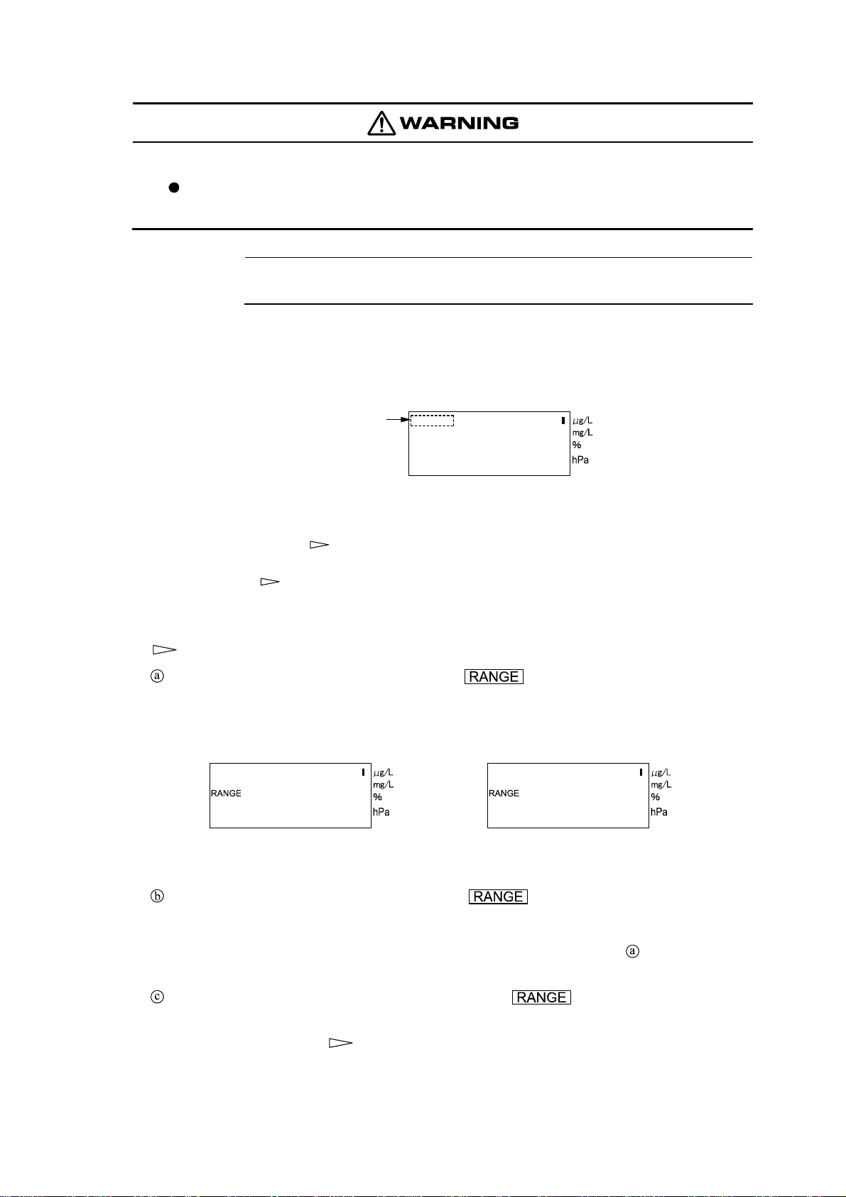
⑤Check the measuring range. ⋅⋅⋅⋅⋅⋅ Check the DO measuring range in the following procedure and
check if it is appropriate for DO value measurement of sample. If necessary, change the range.
3.3(6) “Setting the measuring range”
Check the measuring range low limit. ⋅⋅⋅⋅⋅⋅ Press in the measurement mode (“ST-BY”
is unlit) and check that the low limit of the measurement output range is displayed on the main
display of the “DO measuring range low limit check (4mA)” screen. This is the DO value
corresponding to 4mA DC of the transmission output.
0
4mA 200
20mA
DO Measuring Range Low Limit DO Measuring Range High Limit
Check Screen Check Screen
Check the measuring range high limit. ⋅⋅⋅⋅⋅⋅ Press in the measurement mode and
check that the high limit of the measurement output range is displayed on the main display of
the “DO measuring range high limit check (20mA)” screen. This is the DO value
corresponding to 20mA DC of the transmission output. The screens in step above show an
example when the measuring range is 0.0 to 200.0μg/L.
Return to “DO measured value (DO)” screen. ⋅⋅⋅⋅⋅⋅ Press .
⑥Set the alarm settings. ⋅⋅⋅⋅⋅⋅ Set the necessary alarm settings such as alarm set-points to control
the DO measurement value. 3.3(2) “Alarm setting”

Model: OBM-100H 2.1 Operation Start Procedure
-
17
-
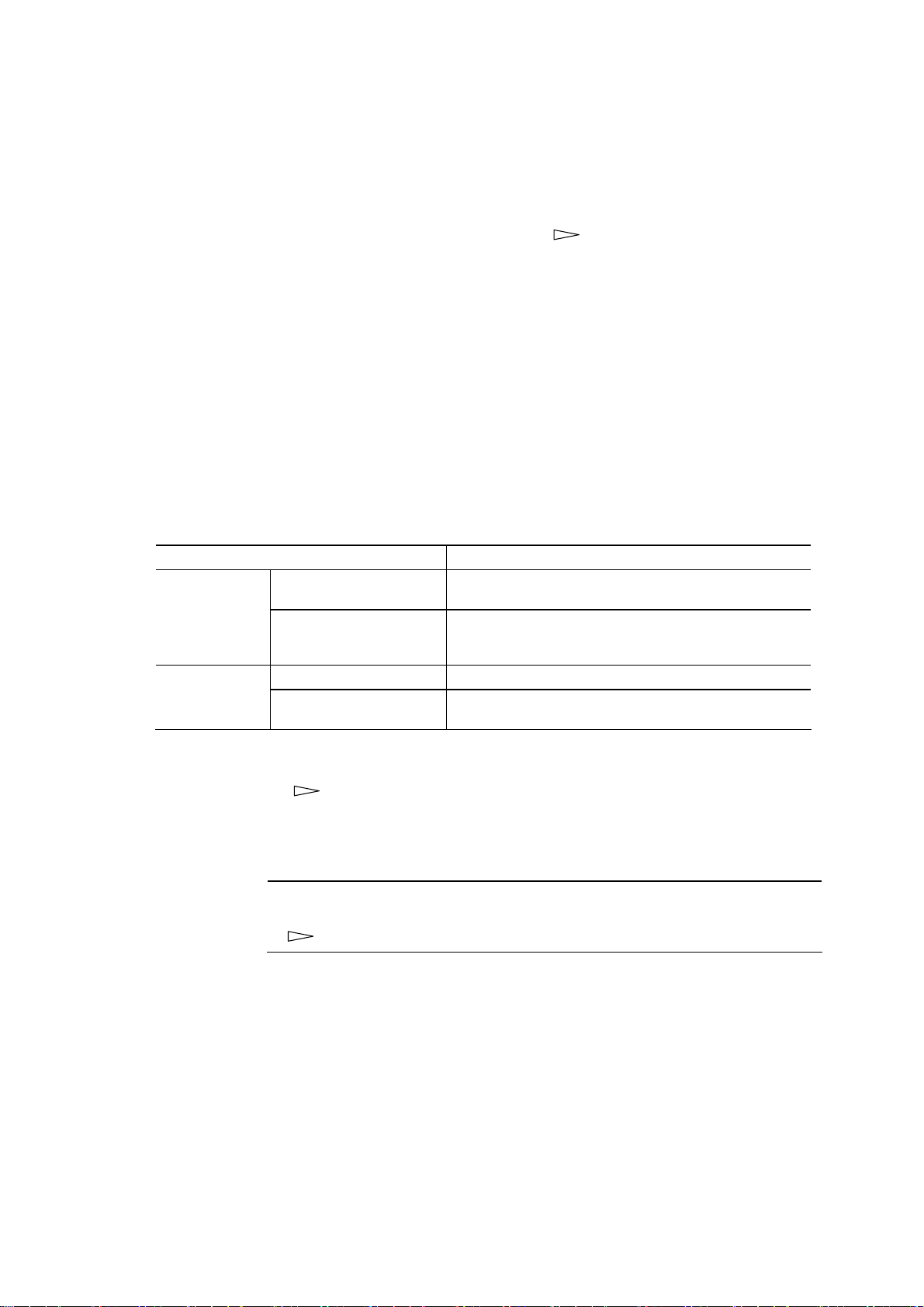
⑦Check other settings. ⋅⋅⋅⋅⋅⋅ Check the factory settings for items shown in the following table.
3.2(5) “Checking other setting values”
•If necessary, change the settings. 3.3(8) “Setting the zero calibration signal value and span
calibration signal value” to 3.3(16) “Setting the measurement mode auto return”
Screens of “Other Setting Values Check Screen Group” and Their Factory Settings
Screens of Other Setting Values
Check Screen Group Factory settings Reference item
◎Zero calibration signal value
check (ZERO) screen .0000μA 3.3(8) “Setting the zero calibration
signal value and span calibration signal
value”
◎Span calibration signal value
check (SPAN) screen 100.0% 3.3(8) “Setting the zero calibration
signal value and span calibration signal
value”
○Burnout check (B.OUT) screen on.H (transmission output
is set to 21mA if an error
occurs)
3.3(9) “Burnout setting”
◎Setting mode transmission output
type check (S.OUT) screen HoLd (Hold) 3.3(10) “Setting mode transmission
output type setting”
◎Transmission response speed
check (RESP) screen Std (Standard) 3.3(11) “Setting the response speed”
◎Calibration stability check on/off
(WAIT) screen on (Valid) 3.3(12) “Setting the stability check
on/off for calibration”
◎Impressed voltage check (V.SET)
screen 650mV 3.3(13) “Setting the impress
voltage”
◎Measurement mode auto return
check (M.RET) screen on (Valid) 3.3(16) “Setting the measurement
mode auto return”
◎Electrode current check (μA)
screen Present value is displayed.
−
◎: Screens that appear always ○: Screens that appear when necessary setting is made
⑧Perform calibration. ⋅⋅⋅⋅⋅⋅ 2.2 “Calibration”
⑨Select the measurement mode screen. ⋅⋅⋅⋅⋅⋅ 3.2(2) “Alarm setting”
⑩Perform calibration 2 weeks later. ⋅⋅⋅⋅⋅⋅ To correct for sensitivity change of the electrode,
perform calibration again 2 weeks after the operation is started. 2.2 “Calibration”
The DO measurement system is now in normal measurement condition.
Model: OBM-100H 2.2 Calibration
-
18
-
2.2 Calibration
(a)It is absolutely necessary for this transmitter to perform calibration before measurement using a
standard solution and adjust the electrode characteristics and the indication of the transmitter.
(b)Though the electrode characteristics changes due to dirt accumulation by sample water when
measurement is continued for a long time, this effect can be eliminated by calibration. Perform
calibration periodically as well after operation is started. 4.1 “Maintenance List”
(c)Zero calibration or span calibration, whichever first, can be performed.
(d)If “AUTO (Zero/Span auto check calibration)” is set, the transmitter automatically determines
whether zero calibration should be performed or span calibration be performed depending on the
signal sent from the electrode. For example, if the electrode is immersed to zero solution, the
transmitter goes to the zero calibration state and if the electrode is placed in the air, the transmitter
goes to the span calibration state.
(e)When “AUTO (Zero/Span auto check calibration)” is set to “Calibration (AUTO etc.)” screen, the
unit indicators μg/L and mg/L switch automatically depending on the concentration of the sample
being measured.
(f) The types of zero calibration and span calibration are shown in the table below. Two methods each
are provided. Select either one and perform zero calibration and span calibration.
Types of Calibration
Types of calibration Description
Zero calibration Zero calibration using a
solution Immerse the electrode to a zero solution (sodium sulfite
solution of 5 to 10%) and perform zero calibration.
Electrical zero calibration Perform zero calibration without using a zero solution by
setting Off (oFF) to the input signal sent from the
electrode using key operation.
Span calibration Span calibration using air Perform calibration by placing the electrode in the air.
Span calibration using air
saturated water Perform span calibration by immersing the electrode to air
saturated water.
(g)To adjust the transmitter indication to the analysis value of sample, first perform these zero and
span calibrations. 3.3(4) “DO value adjustment setting”
(1) Zero calibration using a solution
【IMPORTANT】•Since zero calibration using a solution takes more than 2 hours, set the
“Measurement mode auto return setting” to Invalid (oFF) beforehand.
3.3(16) “Setting the measurement mode auto return”
This is a calibration method using 5 to 10% exsiccated sodium sulfite solution as zero solution.
①Prepare the following items. ⋅⋅⋅⋅⋅⋅ Prepare the following items:
•GR (Guaranteed Reagent) grade exsiccated sodium sulfite (sulfite of soda) ······· 5 to 10g
•Ion-exchange water··················1 to 2L
•Beaker·····································2 pieces (for zero calibration solution and for cleaning water)
②Prepare zero solution. ⋅⋅⋅⋅⋅⋅ Put the ion-exchange water of 100mL in a beaker (to the extent that
the tip end of the electrode can be immersed) and add 5 to 10g of exsiccated sodium sulfite (about
2 spoonfuls). For another beaker, put in the ion-exchange water to use it for cleaning.

Model: OBM-100H 2.2 Calibration
-
19
-
Sodium sulfite (5 to 10g)
Beaker
Ion-exchange water
(100mL)
Zero water Ion-exchange water
(for cleaning)
Preparing Zero Water
③Remove the electrode. ⋅⋅⋅⋅⋅⋅ Close the control valve to stop the sample water and loosen the
fixing nut to remove the electrode.
【IMPORTANT】•The time to leave the electrode in the air must be within 30 minutes. This
is because the time required for the transmitter indication to return to
normal value may take about the same time as that of leaving the
electrode in the air.
Electrode (Model 7561L, etc.)
Flow cell
Lead wire
Connector
Electrode
Fixing nut
Flange
Packing
< Example of Sensor >
Removing the Electrode
④Select the setting mode. ⋅⋅⋅⋅⋅⋅ If the transmitter is in the measurement mode (“ST-BY” is unlit),
press for 3 seconds or more.
•The initial screen of the setting mode appears (“ST-BY” lights).
10.23
DO
Setting Model Initial Screen
⑤Immerse the electrode in zero water. ⋅⋅⋅⋅⋅⋅ Wash the electrode with ion-exchange water and then
immerse it in the prepared zero solution (sodium sulfite solution).


