66
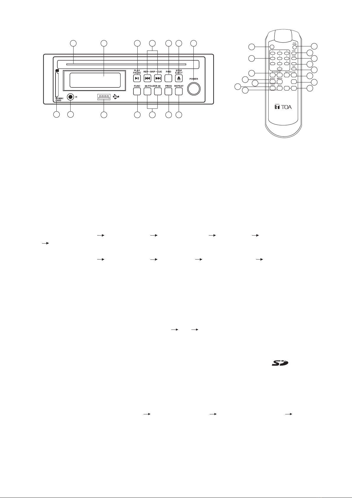
6. AUDIO MUSIC PLAYER
12A345
10
6789
11
12
13
1. POWER : In power OFF mode, press this key to switch ON the power.
In power ON mode, press this key for more than 2 sec. to switch OFF the power.
2. (2A) STOP/EJECT : Press to stop playing CD/USB/SDCard and press again to eject disk.
3. FIND : In MP3 mode : Press this key once FILE search mode changed. Press this key twice ALBUM search
mode changed. If press this keylong time once track isdisplayed. press twice ID3 TAG is displayed.
4. CUE/UP : Press to next track number.
Continued pressed, fast forward during play/pause when pressed for more than 0.7 sec.
REV/DOWN : Press to previous track number.
Continued pressed, fast reverse during play/pause when pressed for more than 0.7sec.
5. PLAY/PAUSE : Press once to start playing, press again to pause.
6. REPEAT :
(In MP3 mode and in USB mode) If this key is pressed, PLAY mode is changed cyclically as shown below.
PLAY ALL
PLAY ALL RANDOM REPEAT TRACK REPEAT FOLDER REPEAT ALL RANDOM REPEAT
In CD mode if this key is pressed, PLAY mode is changed cyclically as shown below.
PLAY ALL RANDOM REPEAT TRACK REPEAT ALL RANDOM REPEAT PLAY ALL
SD Card
FIND
0
POWER
FUNC
vol- vol+
(2C) EJECT : press to eject disk.
(2B) STOP:Press to stop playing (CD/USB/SDCard).
1
14
8
6
2C 16
17
5
2B
7
3
15
4
9
18
19. Slot to insert the CD.
19
7. PROG : Press the PROG button then select a track by pressing the CUE / REV, for once making of
programming,
the maximum limit to 99 election programming, and terminated by pressing PROG.
Then press PLAY to start.
Set to programming mode. In programming mode, all program is cleared when [STOP] key is pressed.
8. FOLDER-DOWN: In stop mode: Skip the starting play folder to previous folder during stop mode, cyclic to the
last folder if it is in the first folder. In normal play mode: Skip the playing file to the previous folder’s first file.
FOLDER-UP: In stop mode: Skip the starting play folder to next folder during stop mode, cyclic to the first
folder if it is in the last folder. In normal play mode : Skip the playing file to the next folder’s first file.
9. FUNC : Press to change cyclically as shown : CD USB CARD.
10. LCD DISPLAY : Display CD status including track number and playing time.
11. USB Connector : Insert the USB ( Support up to 32GB ).
12. IR INFRARED : Picks up signal from the remote control.
13. SD/MMC CARD Connector : Accepts SD Card and MMC Card ( Support up to 32GB ).
14. 0~9 : Use these keys to select the track.
15. ESP : In CD mode, Press “ESP” key.
The ESP display is lit and the set is in electronic anti-shock state. The electronic anti shock time is
about 40 seconds. Press “ESP” key again to cancel the ESP function.
16. Display : When playing a MP3 CD, and key is pressed, the LCD display will be changed cyclically as shown
below : track number and playing time total number of songs name of the playing song total
number of folder and total number of songs.
17. MUTE : In playing mode, press this key to mute, press again to recovery.
18. VOL + : When this key is pressed, the volume will increase by 1dB per step, the max. volume is 30dB.
VOL - : When this key is pressed, the volume will decrease by 1dB per step, the min. volume is 0B.