Item
Name
Function/Description
1
POWER ON-OFF
SWITCH
Applies line power. Two-position
pushbutton switch for on-off modes.
2
METER
Indicates the output level of the
amplifier. At rated output, it shows
0 VU (continuous sine-wave signal
input).
When power is turned on, meter
illuminates.
3
INPUT VOLUME
CONTROLS
Adjust gain of INPUT #1-#6
respectively.
4
BASS CONTROL
Adjust bass response.
Turn clockwise (CW) to boost and
counterclockwise (CCW) to
attenuate the bass response. Tone is
flat at center.
5
TREBLE
CONTROL
Adjust treble response.
Turn CW to boost and CCW to
attenuate the treble response. Tone is
flat at center.
6
TONE SWITCH
Selects IN/DEFEAT of the BASS and
TREBLE CONTROLS. When this
button isdepressed
the BASS
and TREBLE Controls are active.
When pressed again
they
become inactive to make tone flat.
(DEFEAT)
7
MASTER
VOLUME
CONTROL
Adjusts overall gain of unit.
8
OUTPUT SWITCH
This is an output ON/OFF switch.
When pressed
output signal is
obtained at the output terminal.
When pressed again
no output
signal is obtained.
9
HEADPHONE
JACK
Connects to headphones with
impedance of more than 8
10
HEADPHONE
VOLUME
CONTROL
Adjust the volume for headphones.
Turn CW to increase.
11
VU RANGE
SWITCH
Selects meter-sensitivity.
When set to "4dBm" position, the
meter shows 0 VU if the output level
of amplifier is +4dBm. When set to
"18dBm," it shows 0 VU if the
output level is +18dBm.
Usually
set the
switch
to
"4dBm"
position,
since
the
amplifier's rated output is +4dBm.
Place it in "18dBm" position when more output is
provided.
Item
Name
Function/Description
1
AC POWER
SUPPLY CORD
Connects to power source.
2
AC OUTLET
(Unswitched)
Provides AC power for auxiliary
equipment with power consumption
of up to 500W.
3
AC FUSE
(250V 0.3A)
Protects amplifier from excessive
current drain. Replace only with
same type fuse. Refer to qualified
service personnel if fuse blows
repeatedly.
4
OUTPUT
TERMINALS
Connect to power amplifier(s).
5
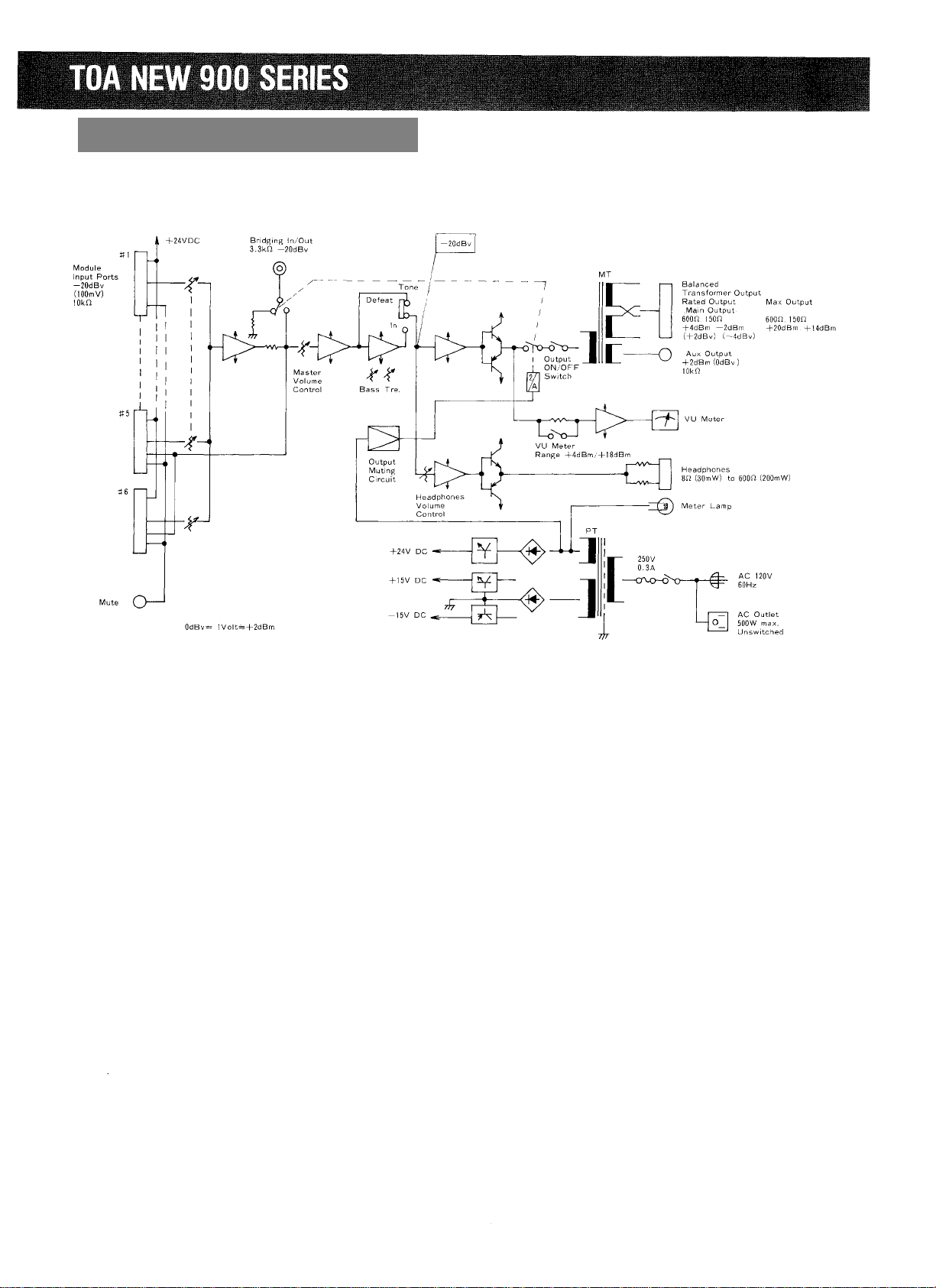
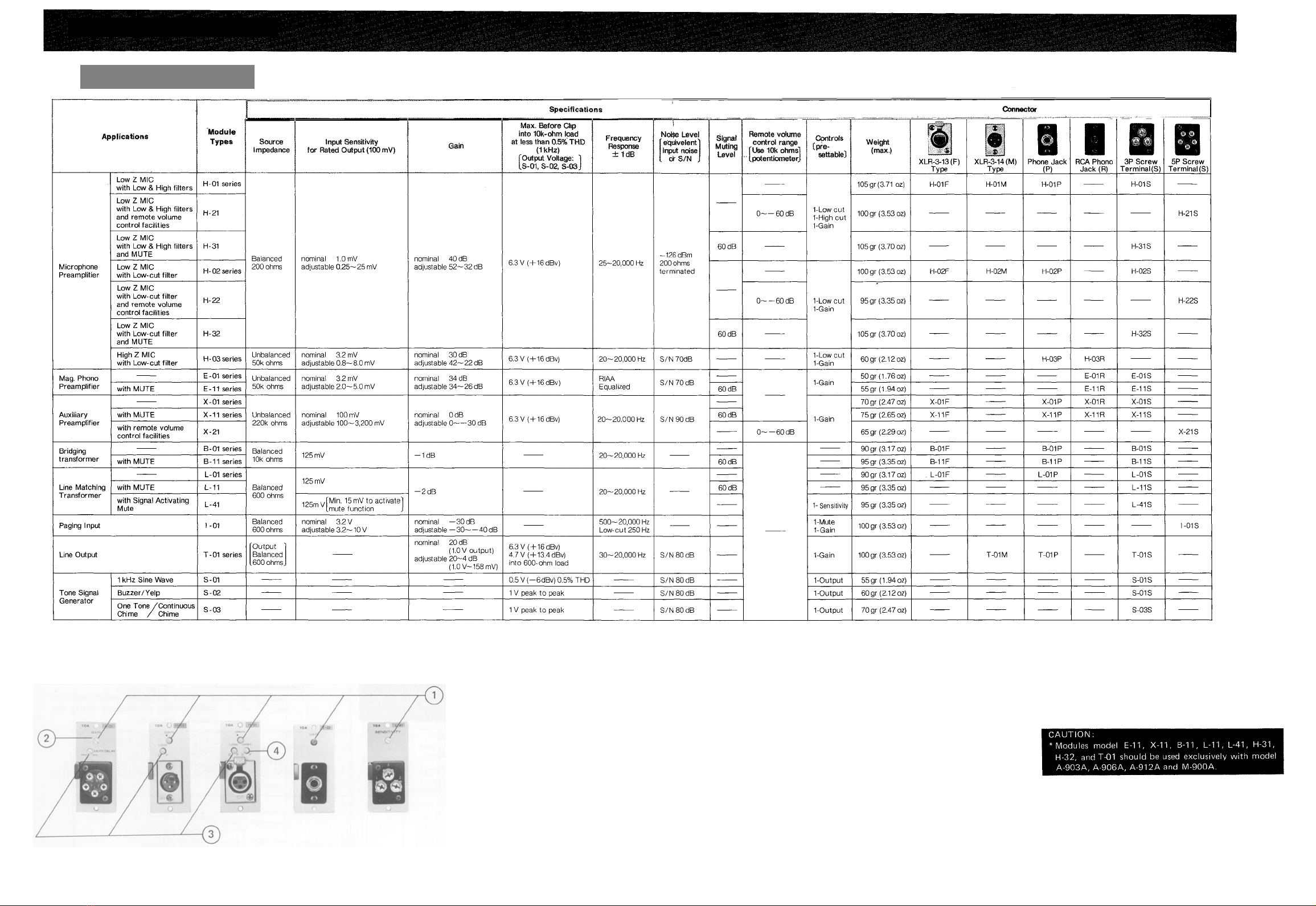
MODULE INPUT
PORTS
Accept PLUG-IN MODULES which
are optionally available. Choose the
desired modules according to
application.
6
AUX OUT
Serves as a sub-output for connecting
other equipment having input
impedance of more than 10k
such
as a tape recorder.
7
BRIDGING
INPUT/OUTPUT
This terminal is used as a mixing bus.
Mixing is achieved when the similar
terminal of another amplifier is
connected to this terminal.
The output level taken from this
terminal is independent of the
MASTER VOLUME CONTROL,
BASS and TREBLE CONTROLS, so
that the terminal can also be used as
recording output. The input
impedances of the equipment to be
connected here should be 10k
or
higher.
8
MUTE
TERMINAL
With modules employing muting
function, which are optionally
available, the input signals fed to the
modules are muted by short-circuiting
at this terminal.
9
EARTH
TERMINAL
Normally connects to a record
player's ground.
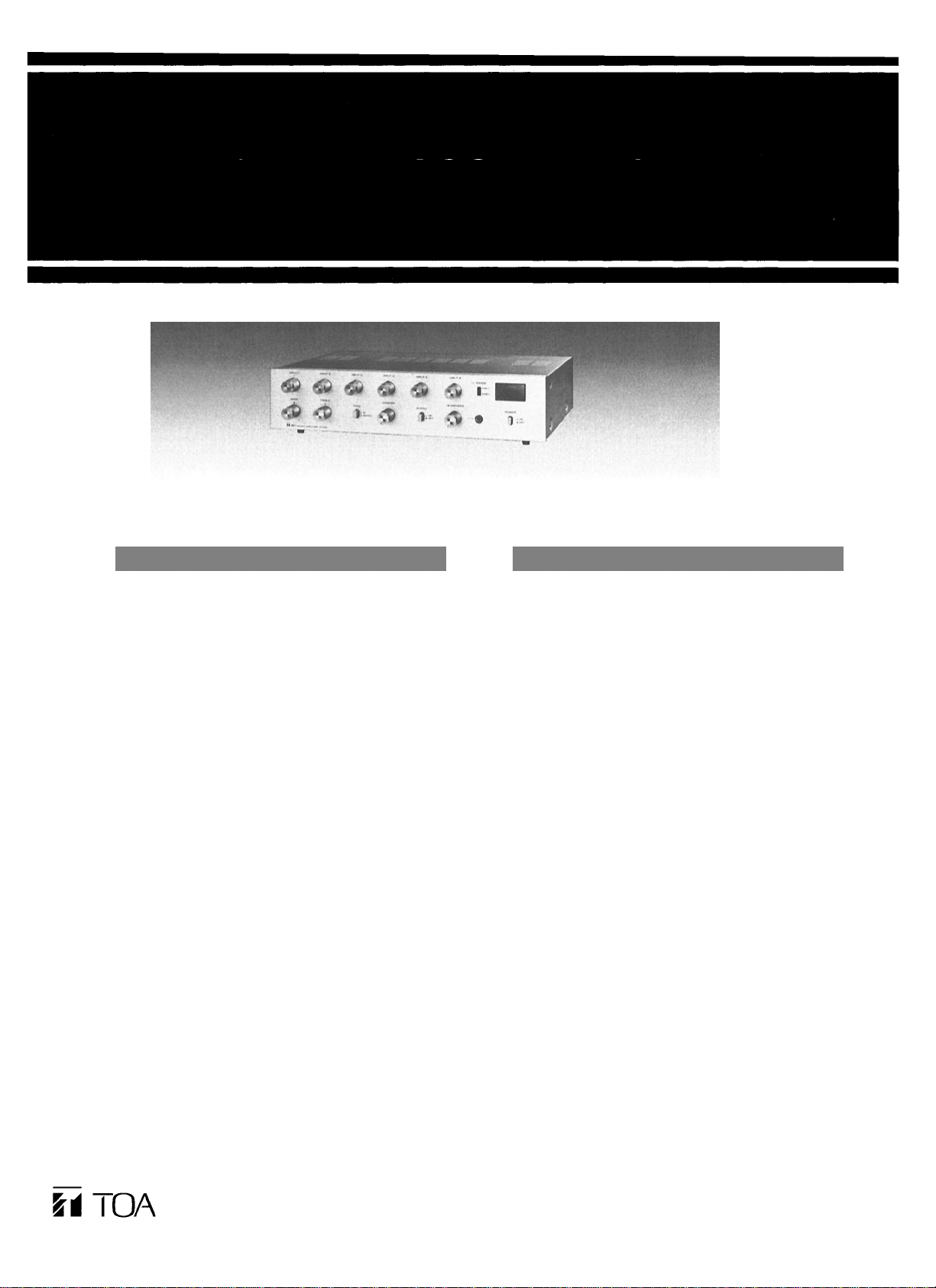
Front Panel Controls and Features
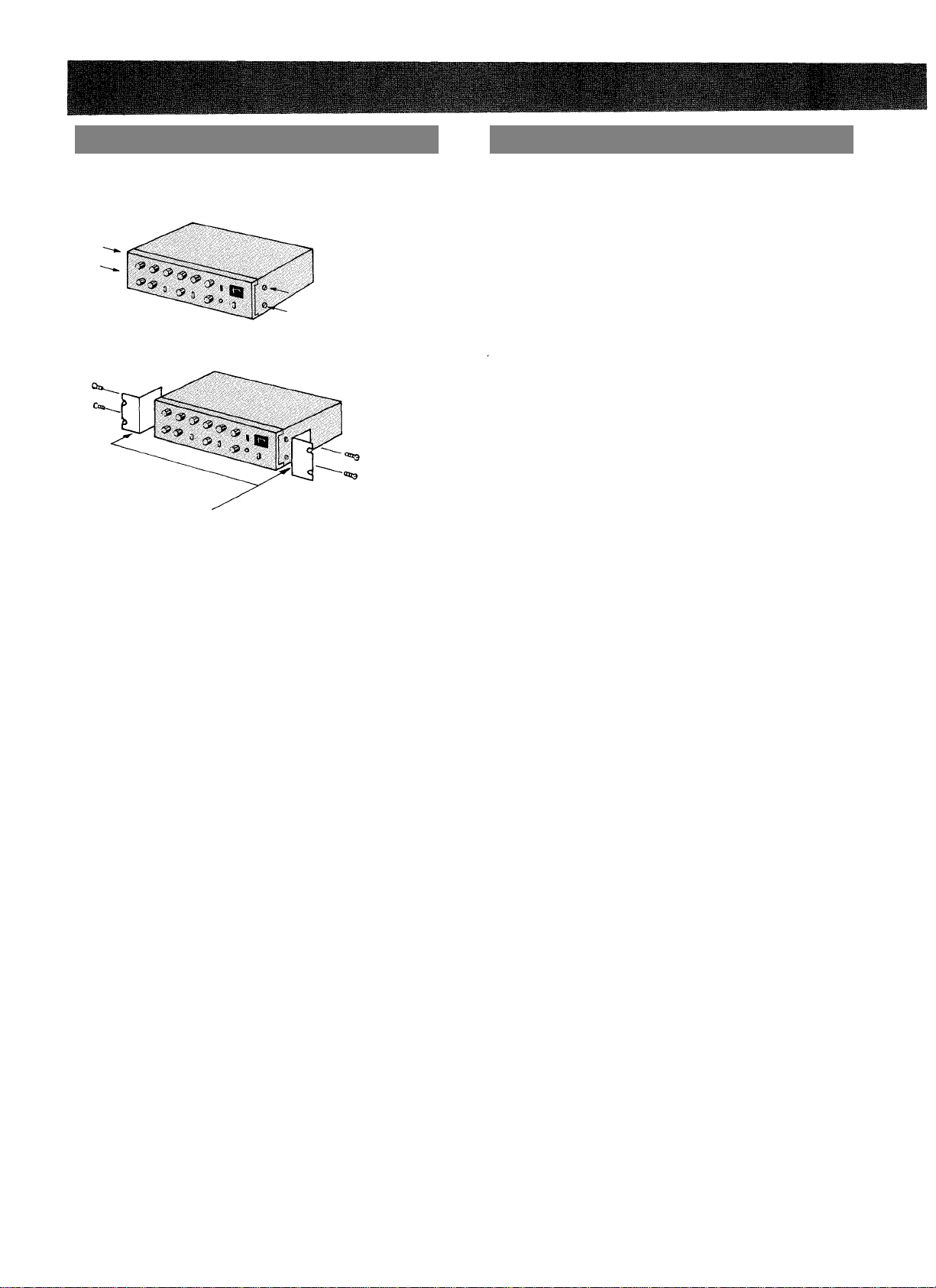
Rear Panel Controls and Features
—1 —