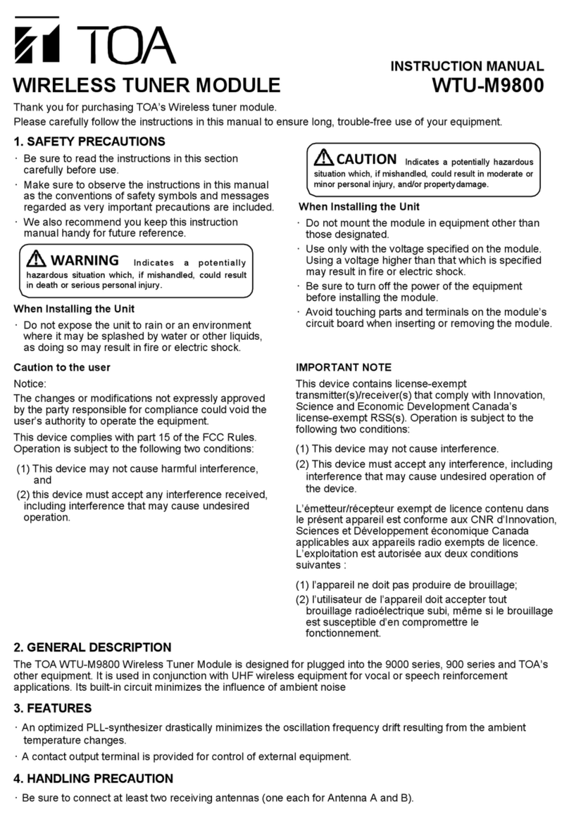
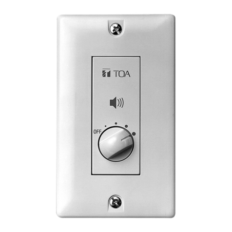
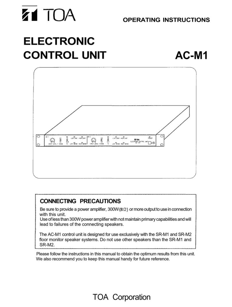
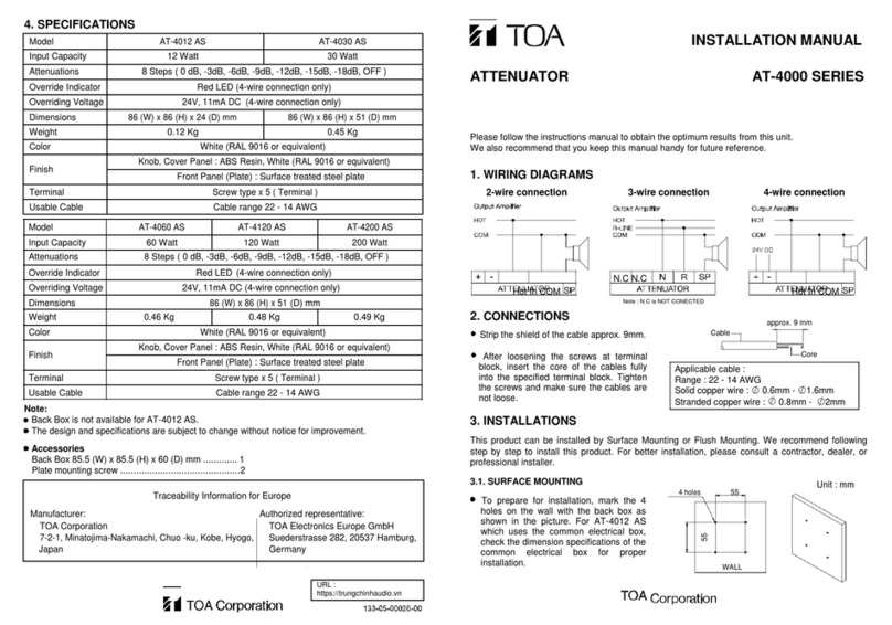
Toa AC-F1 User manual

ELECTRONIC
CONTROL UNIT
Operating Instructions
AC-F1
AC-L1
AC-F1
AC-L1
Please follow the instructions in this manual to obtain the optimum results from these units.
We also recommend you to keep this manual handy for future reference.
TOA Corporation
CONNECTION PRECAUTION
Be sure to provide a power amplifier, 300W (8 ) or more output to use in connection
with these units.
Use of less than 300W power amplifier will not maintain primary capabilities and will
lead to failures of the connecting speakers.
These AC-F1/AC-L1 can exclusively be used for the SR-F1 speaker system and the
SR-L1 super woofer system. Do not use other speakers than the SR-F1 and the
SR-L1.

Contents
User care
General description
Features
4
4
5
Panel facilities
AC- F1 [Front view]
[Rear view]
AC- L1 [Front view]
[Rear view]
Connection
6
7
8
9
Basic block diagram
Back wiring connection with external equipment (1)
Back wiring connection with external equipment (2)
SR-F1 single system
10
10
11
12
13
14
15
15
16
Installation
Block diagrams
Specifications
Accessories
Appearance

User care
Never disassemble unit and touch the inside or insert metallic stuff into the inside as this may lead to a
breakage or shock hazard.
When water enters, a breakage or shock hazard can be caused. To prevent an accident, immediately
unplug the power cord from the wall AC outlet and contact your nearest TOA dealer.
Wipe unit down with a soft cloth when cleaning the exterior of unit. Never use such volatile liquids as
thinner and benzine because their use may discolor unit.
Ensure to ground unit.
General description
The AC-F1 and the AC-L1 Electronic control units are designed for use with the SR-F1 speaker system
and the SR-L1 super woofer system, for single channel full range speaker and super woofer.
These electronic control units provide the channel divider to divide respective frequency range between
the speaker units, and can realize smooth phase characteristics in the speaker system, by according with
the phase in crossover frequency while correcting time lag for the divided frequency range each other
between the speaker units.
In high frequency range in combination with the compression driver and the constant directivity (CD) horn,
the horn equalizer employs to provide smooth phase and amplitude characteristics.
To moderate the frequency response (3~4kHz) susceptible to saturation to listener's ears at the highest
sound pressure, dynamic equalizer is provided to control such frequency response.
Limiter is provided to prevent the speaker units from over-driven and damage in respective frequency
range and not to arise power amplifier clipping.
When suspending the SR-F1 to the ceiling, crossover select switch is provided to sharply cut off the
crossover frequency between the super woofer and the woofer.
Quality sound is realized by use of selected electronic parts as OP amplifier, condensers etc.
— 4 —

Features
Time lag between speaker units in the speaker system is corrected.
Provided the frequency dividing network function.
Accorded with phase at the crossover frequency.
Limiter is provided to prevent the speaker units from over-driven and damage in each frequency range
and not to arise power amplifier clipping.
Dynamic equalizer is provided to correct general characteristics of the speaker system, and to control the
frequency response (3~4kHz) susceptible to saturation to listener's ears.
Crossover select switch is provided to control when the SR-F1 is suspended to the ceiling.
Strictly selected parts and component parts are used for materializing quality sound.
Can be mounted on 19" EIA standard rack, (one size)
The AC-F1 and the AC-L1 are designed enabling to use with the SR-F1 and the SR-L1.
Input and output are used the electronically balanced XLR type connector.
(Pin No.3 : HOT, No.2 : COLD and No.1 : GND)
— 5 —

Panel facilities
model AC-F1
[Front view]
Input level control (INPUT LEVEL)
Input level control adjusts the input level of AC-F1.
It is usually used to turn fully clockwise (Level 10), and adjusts at 26dB of each power amplifier gain for
the super woofer, the woofer and the driver.
Low limit indicator (LOW LIMIT)
Low limit indicator comes on when the low limiter circuit starts to employ with signal of low sense input
terminal. In case the indicator very often flashes, adjust the input level until it occasionally flashes.
When adjusting by the input level control, the low level control of the AC-L1 should be set at same
position as the input level control of the AC-F1.
High limit indicator (HIGH LIMIT)
High limit indicator comes on when the high limiter circuit starts to employ with signal of high sense
input terminal. In case the indicator very often flashes, adjust the input level until it occasionally flashes.
When adjusting by the input level control, the low level control of the AC-L1 should be set at same
position as the input level control of the AC-F1.
Dynamic equalizer indicator (D. EQ)
Dynamic equalizer indicator comes on when the dynamic equalizer circuit starts to employ with signal of
high sense input terminal.
Low sense input indicator (LOW SENSE)
Low sense input indicator comes on when signal is input to the low sense input terminal.
High sense input indicator (HIGH SENSE)
High sense input indicator comes on when signal is input to the high sense input terminal.
Power indicator
Power indicator comes on when the power switch is ON.
Power switch (POWER)
Press this switch to turn power ON or press it again to turn power OFF.
— 6 —

[Rear view]
Input connector (INPUT)
Input connector for signal is used the electronically balanced XLR type connector.
Low output connector (LOW OUT)
Output connector to the power amplifier for low frequency range is used the electronically balanced
XLR type connector.
High output connector (HIGH OUT)
Output connector to the power amplifier for high frequency range is used the electronically balanced
XLR type connector.
Low sense input terminal (LOW SENSE)
Input terminal for inputting signal from the power amplifier output for low frequency range is used the
electronically balanced screw terminal.
Connect to accord with polarities
input terminal.
between the power amplifier output terminal and the sense
High sense input terminal (HIGH SENSE)
Input terminal for inputting signal from the power amplifier output for the high frequency range is used
the electronically balanced screw terminal.
Connect to accord with polarities
between the power amplifier output terminal and the sense
input terminal.
Earth terminal
Be sure to ground the unit.
Fuse
When the fuse blew, ensure to replace it with the same type
fuse after confirming its causes and countermeasures. (Be sure
unplug the power cord before replacing with a new fuse.)
Use of other fuses than the same type fuse will lead to failures
of unit.
— 7 —
Fuse rating
220 - 240V
version
120V
version
250V
T80mA
250V
0.2A

model AC-L1
[Front view]
Low level control (LOW LEVEL)
Low level control adjusts the low level of AC-L1.
It is usually used to turn fully clockwise (Level 10), and adjusts at 26dB of each power amplifier gain for
the super woofer, the woofer and the driver. It can not adjust high output level.
Low limit indicator (LOW LIMIT)
Low limit indicator comes on when the low limiter circuit starts to employ with signal of low sense input
terminal. In case the indicator very often flashes, adjust the input level until it occasionally flashes.
When adjusting by the low level control, the input level control of the AC-F1 should be set at same
position as the low level control of the AC-L1.
Low sense input indicator (LOW SENSE)
Low sense indicator comes on when signal is input to the low sense input terminal.
Power indicator
Power indicator comes on when the power switch is ON.
Power switch (POWER)
Press this switch to turn power ON or press it again to turn power OFF.
— 8 —

Input connector (INPUT)
Input connector for signal is used the electronically balanced XLR type connector.
Crossover select switch (CROSSOVER)
Crossover select switch can change the crossover filter to set the frequency range between the SR-L1
(super woofer system) and the SR-F1 (speaker system). Usually set the crossover select switch to
OUT.
Set it to IN if the SR-F1 is suspended to the ceiling or if the distance between the SR-F1 and the SR-L1
is installed apart.
Low output connector (LOW OUT)
Output connector to the power amplifier for the super woofer is used the electronically balanced XLR
type connector.
High output connector (HIGH OUT)
Output of this connector connects to the input of the AC-F1, and the connector is used the electronically
balanced XLR type connector.
Low sense input terminal (LOW SENSE)
Low sense input terminal for inputting signal from the power amplifier output for the super woofer is
used the electronically balanced screw terminal.
[Rear view]
Connect to accord with polarities
input terminal.
between the power amplifier output connector and the sense
Earth terminal
Be sure to ground the unit.
Fuse
When the fuse blew, ensure to replace it with the same type
fuse after confirming its causes and countermeasures. (Be sure
unplug the power cord before replacing with a new fuse.)
Use of other fuses than the same type fuse will lead to failures
of unit.
Fuse rating
— 9 —
220 - 240V
version
120V
version
250V
T80mA
250V
0.2A

Connection
Basic block diagram
AC-F1
INPUT
HIGH OUT
LOW OUT
HIGH SENSE
LOW SENSE
HIGH OUT
INPUT
Mixer/
Preamplifier
AC-L1
LOW OUT
LOW SENSE
Power amplifier
SR-F1
SR-L1
Connect a power amplifier, 300W or more output.
Back wiring connection of with external equipment (1)
When one SR-F1 is mounted on the SR-L1
AC-F1
AC-L1
Power amplifier
Power amplifier
— 10 —
Mixer/Preamplifier
SR-F1
SR-L1

Back wiring connection of with external equipment (2)
When two SR-F1 are mounted on the SR-L1
AC-F1
AC-L1
Mixer/Preamplifier
Power amplifier
Power amplifier
— 11 —
SR-F1
SR-L1

SR-F1 single system
Block diagram
Mixer/
Preamplifier
INPUT
HIGH OUT
AC-F1
Power amplifier
LOW OUT
HIGH SENSE
LOW SENSE
SR-F1
Connect a power amplifier, 300W
or more output.
Connection
Mixer/Preamplifier
AC-F1
Power amplifier
SR-F1
— 12 —

Installation
Mount the speakers arranging their front edges as shown in the figure.
For details, refer to "Operating Instructions of the speaker systems".
When one SR-F1 is mounted on the SR-L1
When two SR-F1 are mounted on the SR-L1
Top view
SR-L1
SR-F1
Front view
SR-L1
SR-L1
SR-F1
SR-L1
When the SR-F1 mounting on the SR-L1 is used, the crossover select switch of AC-L1 is turned to OUT.
After setting the switch, confirm sound characteristics in actual operation.
In some cases, better characteristics are obtainable by turning the switch to IN according to the
environmental conditions installed the speakers.
Crossover select switch is turned to IN when the SR-F1 is suspended to the ceiling.
Refer to "Operating instructions of the SR-F1/SR-L1" on connection diagrams with the speakers and power
amplifiers. Unless all polarities are accorded, these speaker systems are not employed.
— 13 —

Block diagram
— 14 —

Specifications
Model
Input
Input impedance
Rated input level
Max. input level
Sense input
Sense input impedance
Output
Output impedance
Rated output level
Max. output level
Crossover frequency
Distortion
Hum & Noise
Indicators
Front panel operation
Rear panel operation
Power requirement
Power consumption
Weight
AC-F1
AC-L1
Electronically balanced(Cannon XLR-3-31 or equivalent)
20k (Balanced)
10k (Unbalanced)
+4dB (Pin No.3 : HOT, No.2 : COLD and No.1 : GND)
+26dB
Electronically balanced
(4P screw terminal)
Electronically balanced
(2P screw terminal)
10k
Electronically balanced (Cannon XLR-3-32 or equivalent)
600 (Balanced)
+4dB
+26dB (Balanced)
+20dB (Unbalanced)
1kHz
125Hz
Less than 0.05%(+4dB 1kHz)
Less than -90dB (20Hz~20kHz)
- Power : green LED
-Sense input : green LED
(LOW SENSE, HIGH SENSE)
- Limit : red LED
(LOW LIMIT, HIGH LIMIT)
- Dynamic Equalizer: green LED
(D.EQ)
Input level control
Power switch
—
- Power : green LED
-Sense input : green LED
(LOW SENSE)
- Limit : red LED
(LOW LIMIT)
Low level control
Power switch
Crossover select switch
AC Mains, 50Hz/60Hz
12W 120V version
16W 220V -240V version
1 0W 120V version
12W 220V -240V version
3.7kg(8.16lb.)
Specifications are subject to change without notice.
OdB=0.775Vrms
Accessories
Fuse
Warranty card (for USA and Canada only)
Operating instructions
1
1
1
— 15 —

Appearance
AC-F1
TOA Corporation
KOBE. JAPAN
133-02-996-30
AC-L1
Other manuals for AC-F1
1
This manual suits for next models
1
Table of contents
Other Toa Control Unit manuals
Popular Control Unit manuals by other brands

Silicon Laboratories
Silicon Laboratories SLWRB4306D user guide

ADDAC System
ADDAC System ADDAC222 user guide

DEEP SEA ELECTRONICS
DEEP SEA ELECTRONICS DSECONTROL DSE7000 Series Operator's manual

Radial Engineering
Radial Engineering Space Heater 500 user guide

Bosch
Bosch WPH operating instructions

Evco
Evco EVBOX1 EVB1204 installation guide