manuals.online logo
Brands
  1. Home
  2. •
  3. Brands
  4. •
  5. Toa
  6. •
  7. Control Unit
  8. •
  9. Toa AT-4012B-EB User manual

Toa AT-4012B-EB User manual

This manual suits for next models

4

Other Toa Control Unit manuals

Toa D-2000DA1 User manual

Toa

Toa D-2000DA1 User manual

Toa AT-4060 AS User manual

Toa

Toa AT-4060 AS User manual

Toa WTU-M9800 User manual

Toa

Toa WTU-M9800 User manual

Toa AC-F1 User manual

Toa

Toa AC-F1 User manual

Toa ZM-9001 User manual

Toa

Toa ZM-9001 User manual

Toa SX-200IP User manual

Toa

Toa SX-200IP User manual

Toa COBRANET User manual

Toa

Toa COBRANET User manual

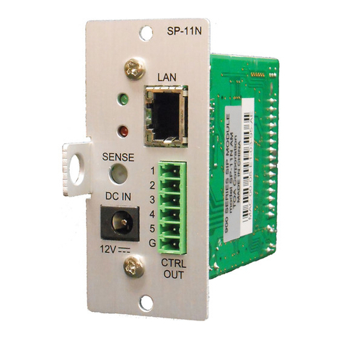
Toa SP-11N User manual

Toa

Toa SP-11N User manual

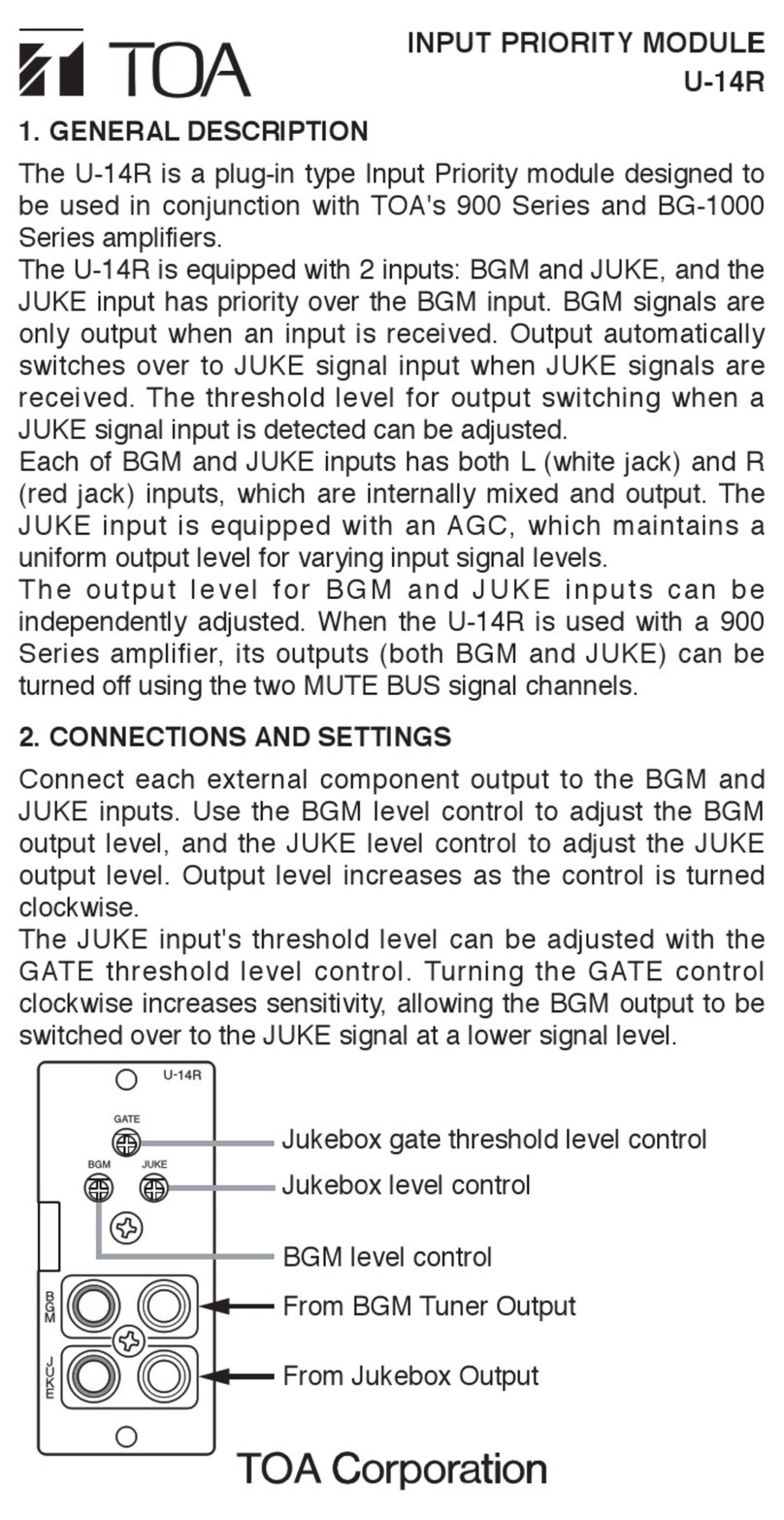
Toa U-14R User manual

Toa

Toa U-14R User manual

Toa AT-4000 Series User manual

Toa

Toa AT-4000 Series User manual

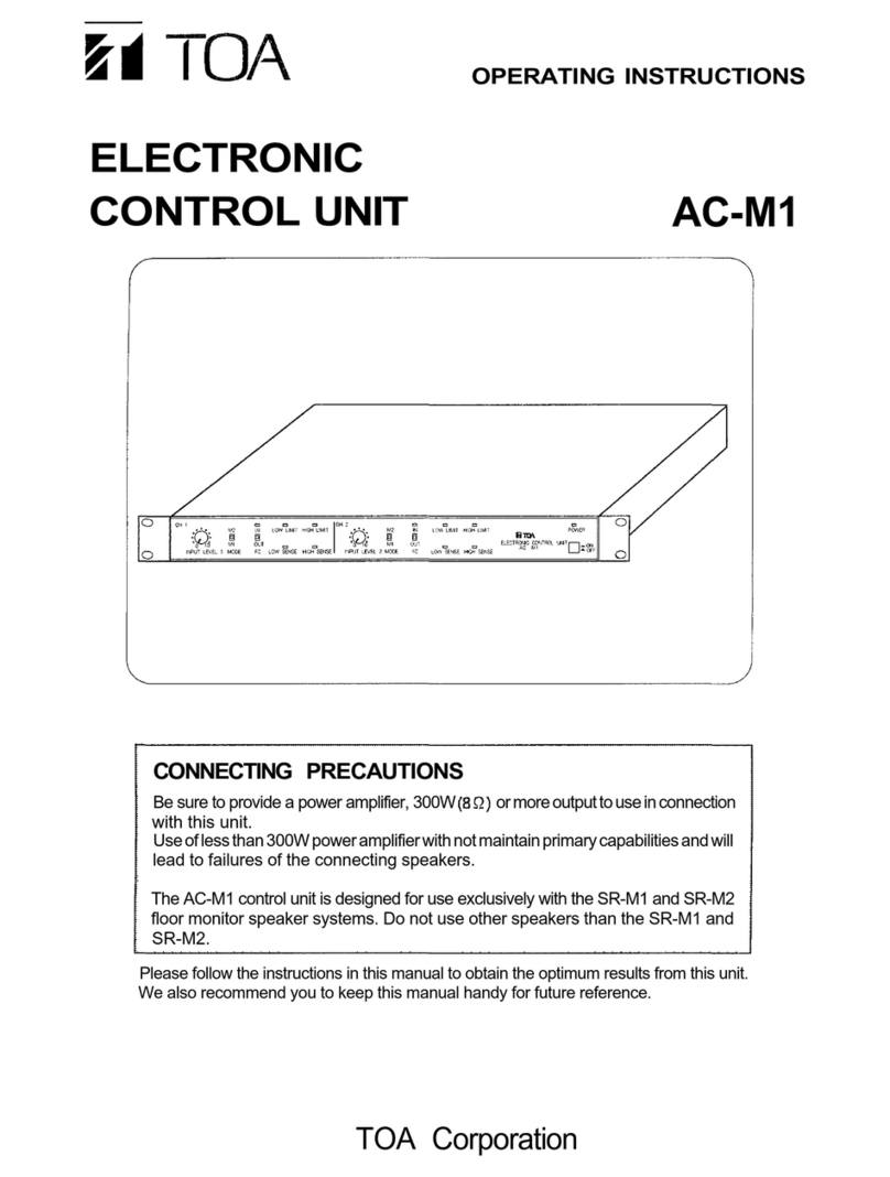
Toa AC-M1 User manual

Toa

Toa AC-M1 User manual

Toa AT-063Ap User manual

Toa

Toa AT-063Ap User manual

Toa IP-300XI User manual

Toa

Toa IP-300XI User manual

Toa IP-100XI User manual

Toa

Toa IP-100XI User manual

Toa DX-0808 User manual

Toa

Toa DX-0808 User manual

Popular Control Unit manuals by other brands

Seitz 14A80 user manual

Seitz

Seitz 14A80 user manual

Wilo RS485 Installation and operating instructions

Wilo

Wilo RS485 Installation and operating instructions

Becker CentralControl CC41 Commissioning Instruction

Becker

Becker CentralControl CC41 Commissioning Instruction

SICK CDB650 operating instructions

SICK

SICK CDB650 operating instructions

Panduit NetKey NKP5E88M Series installation instructions

Panduit

Panduit NetKey NKP5E88M Series installation instructions

MX Options Concentric Petite Fitting instructions

MX

MX Options Concentric Petite Fitting instructions

Clean Water Systems Fleck 2510 Installation & start?up guide

Clean Water Systems

Clean Water Systems Fleck 2510 Installation & start?up guide

Fairchild FSB44104A user guide

Fairchild

Fairchild FSB44104A user guide

LEGRAND Wattstopper LMIN-104 installation instructions

LEGRAND

LEGRAND Wattstopper LMIN-104 installation instructions

PMK ATT10BNCS instruction manual

PMK

PMK ATT10BNCS instruction manual

Tektronix TDS3FFT user manual

Tektronix

Tektronix TDS3FFT user manual

Woodward easYgen Technical manual

Woodward

Woodward easYgen Technical manual

Balluff BNI EIP-502-105-R015 user guide

Balluff

Balluff BNI EIP-502-105-R015 user guide

NXP Semiconductors TWR-LS1021A Getting started

NXP Semiconductors

NXP Semiconductors TWR-LS1021A Getting started

Advantech PCM-3117 Startup manual

Advantech

Advantech PCM-3117 Startup manual

Danfoss MCO 101 manual

Danfoss

Danfoss MCO 101 manual

Moons' Lin Engineering R701P user manual

Moons'

Moons' Lin Engineering R701P user manual

Aventics RV1 operating instructions

Aventics

Aventics RV1 operating instructions

manuals.online logo
manuals.online logoBrands
  • About & Mission
  • Contact us
  • Privacy Policy
  • Terms and Conditions

Copyright 2025 Manuals.Online. All Rights Reserved.

2. CONNECTIONS
1. WIRING DIAGRAMS
Please follow the instructions manual to obtain the optimum results from this unit.
We also recommend that you keep this manual handy for future reference.
2-wire connection 3-wire connection 4-wire connection
4. SPECIFICATIONS
Model
Attenuations
Input Capacity
Override Indicator
Overriding Voltage
Dimensions
Weight
Color
Finish
AT-4012B-EB AT-4030B-EB
AT-4060B-EB
12 W 30 W
60 W
8 Steps ( 0 dB, -3dB, -6dB, -9dB, -12dB, -15dB, -18dB, OFF )
Red LED (4-wire connection only)
24V DC, 11mA (4-wire connection only)
86 (w) x 86 (h) x 52 (d) mm 86 (w) x 86 (h) x 79 (d) mm
White (RAL 9016 or equivalent)
Knob, Cover Panel : ABS Resin, White (RAL 9016 or equivalent)
Note:
The design and specifications are subject to change without notice for improvement.
Accessories
Back Box 85.5 (w) x 85.5 (h) x 60 (d) mm ................. 1
Plate mounting screw ............................................... 2
This product can be installed by Surface Mounting or Flush Mounting. We recommend following
step by step to install this product. For better installation, please consult a contractor, dealer, or
professional installer.
3.1. SURFACE MOUNTING
3. INSTALLATIONS
55
55
4 holes
WALL
Applicable cable :
Range : 22 - 14 AWG
Solid copper wire : 0.6mm - 1.6mm
Stranded copper wire : 0.8mm - 2mm
Unit : mm
Strip the shield of the cable approx. 9mm.
After loosening the screws at terminal
block, insert the core of the cables fully
into the specified terminal block. Tighten
the screws and make sure the cables are
not loose.
To prepare for installation, mark the 4
holes on the wall with the back box as
shown in the picture.
Hot In COM
approx. 9 mm
Cable
Core
N.C N.C
Hot In COM
Note : N.C is NOT CONNECTED
Terminal
Usable Cable Cable range 22 - 14 AWG
Screw type x 5 ( Terminals )
Front Panel (Plate) : Surface treated steel plate
0.12 kg 0.45 kg
0.46 kg
Model
Attenuations
Input Capacity
Override Indicator
Overriding Voltage
Dimensions
Weight
Color
Finish
AT-4120B-EB AT-4200B-EB
120 W 200 W
8 Steps ( 0 dB, -3dB, -6dB, -9dB, -12dB, -15dB, -18dB, OFF )
Red LED (4-wire connection only)
86 (w) x 86 (h) x 79 (d) mm
White (RAL 9016 or equivalent)
Knob, Cover Panel : ABS Resin, White (RAL 9016 or equivalent)
Terminal
Usable Cable Cable range 22 - 14 AWG
Screw type x 5 ( Terminals )
Front Panel (Plate) : Surface treated steel plate
0.48 kg 0.49 kg
AT-4012B-EB
ATTENUATOR
INSTALLATION MANUAL
Traceability Information for Europe
Manufacturer:
TOA Corporation
7-2-1, Minatojima-Nakamachi, Chuo-ku, Kobe, Hyogo,
Japan
Authorized representative:
TOA Electronics Europe GmbH
Suederstrasse 282, 20537 Hamburg,
Germany
24V DC, 11mA (4-wire connection only)
AT-4030B-EB
AT-4060B-EB
AT-4120B-EB
AT-4200B-EB
133-05-00045-00
Screw M3 X 20
Cover Panel
Main unit attenuator
3.2. FLUSH MOUNTING
Flush mounting installation can be implemented in 2 ways, with back box or without back box.
3.2.1 FLUSH MOUNTING WITH BACK BOX
3.2.2 FLUSH MOUNTING WITHOUT BACK BOX
Install the back box with suitable
screws on the surface of the wall.
Connect the recommended cable to
the terminal.
WARNING :
Do not supply 24V DC when connect-
ing 4-wire attenuator system.
Install the main unit to the back box.
Attach the cover panel to the main
unit attenuator until the hook mount
clips perfectly.
Cut this area for
the lane cables.
Step 1.
Step 2.
Step 3.
Step 4.
Unit : mm
65 - 70
69 - 73
WALL
To prepare for installation, mark the
opening on the wall with rectangular
pattern as shown in the picture.
Install the back box inside the wall.
Connect the recommended cable to
the terminal.
WARNING :
Do not supply 24V DC when connect-
ing 4-wire attenuator system.
Install the main unit to the back box.
Attach the cover panel to the main
unit attenuator until the hook mount
clips perfectly.
Step 1.
Step 2.
Step 3.
Step 4.
Cover Panel
Screw M3 X 20
Main unit Attenuator
Support
To prepare for installation, mark the
opening on the wall as shown in the
picture. This mounting method can be
used for all models.
Make opening on the wall.
Connect the recommended cable to
the terminal.
WARNING :
Do not supply 24V DC when
connecting 4-wire attenuator
system.
Install the main unit directly to the
wall using screws that are suitable
for the kind of wall.
Attach the cover panel to the main
unit attenuator until the hook mount
clips perfectly.
Step 1.
Step 2.
Step 3.
Step 4.
57 - 60
72
34.5 - 36.5
36
2 holes
WALL
Cover Panel
Screw
Main unit Attenuator
69 - 73
Unit : mm
Back Box
Support
4
1
2
3
2
4
3
1
2
4
3
1
Cut this area for
the lane cables.