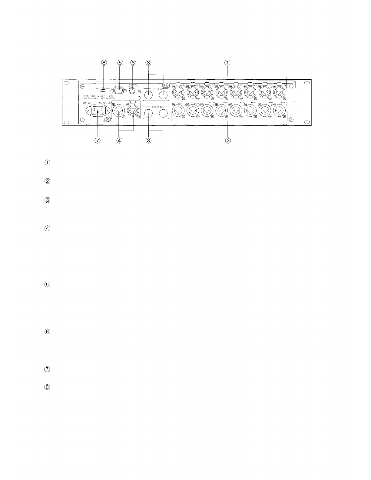
[REAR PANEL]
Input connector [INPUT 1,2, •••••• 8]
An electronically-balanced XLR connector.
Output
connector
[OUTPUT
1,2,
••••••
8]
An electronically-balanced XLR connector.
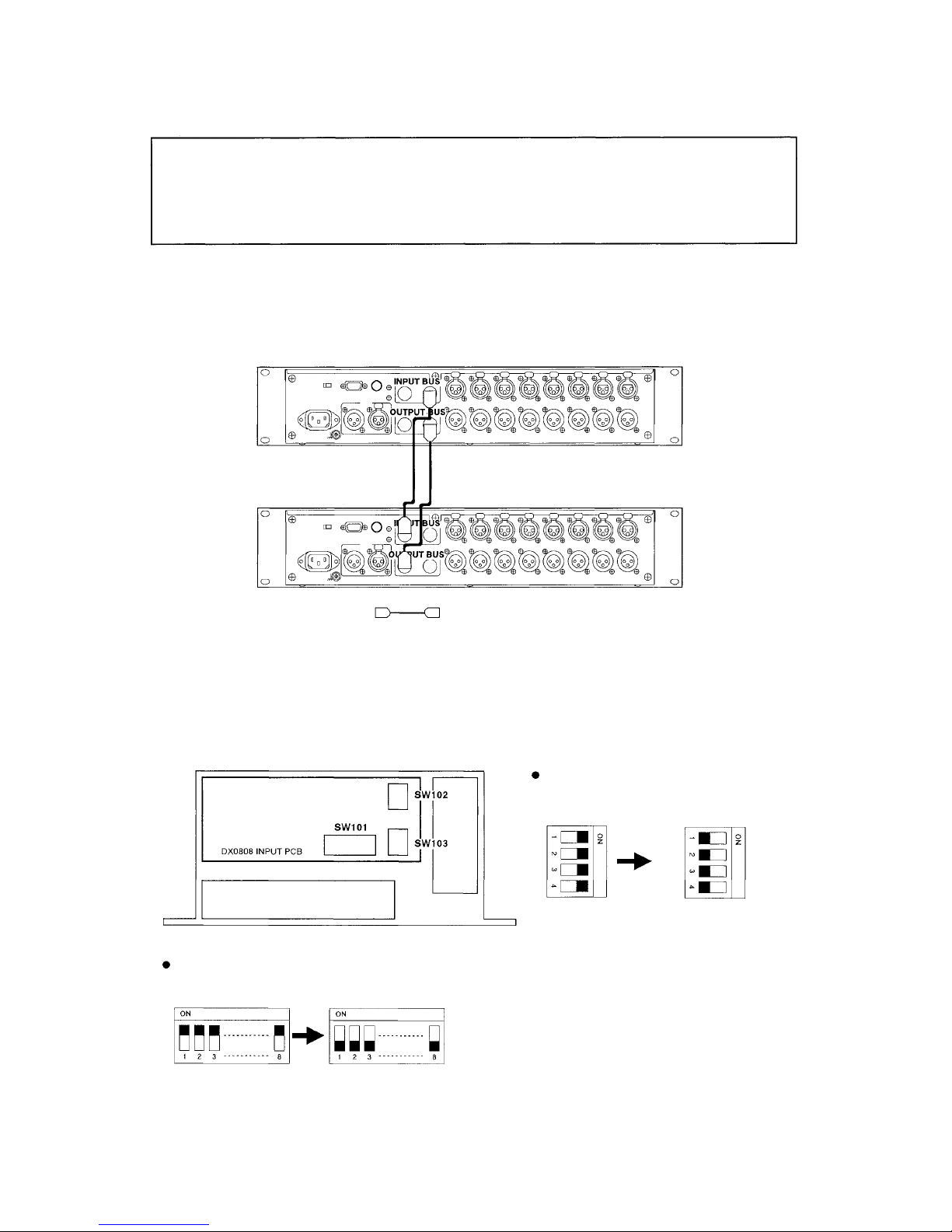
Input bus connector [INPUT BUS] /Output bus connector [OUTPUT BUS]
These connectors are used to expand the input and output. When expanding, the corresponding unit's
internal switch must be set. For details, refer to p.10 "10. EXPANSION AND INTERNAL SWITCH SETTING".
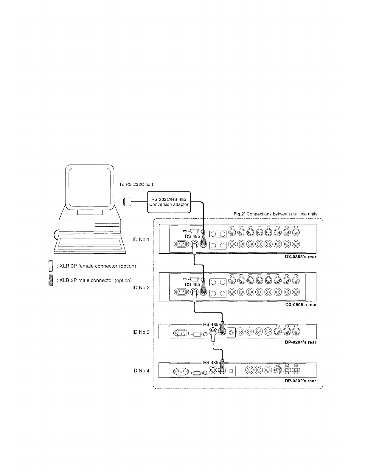
RS-485 communications port [RS-485]
A 3-pin XLR connector for RS-485 communications. This connector can only be used when the
communications port selection switch located in the front pocket is set to "RS-485". When simultaneously
controlling two or more units, use this port and connect each unit in turn. A mode conversion adaptor is
required because data are usually transmitted from a personal computer in RS-232C mode. For details,
refer to p.6 "6. PERSONAL COMPUTER CONNECTIONS".
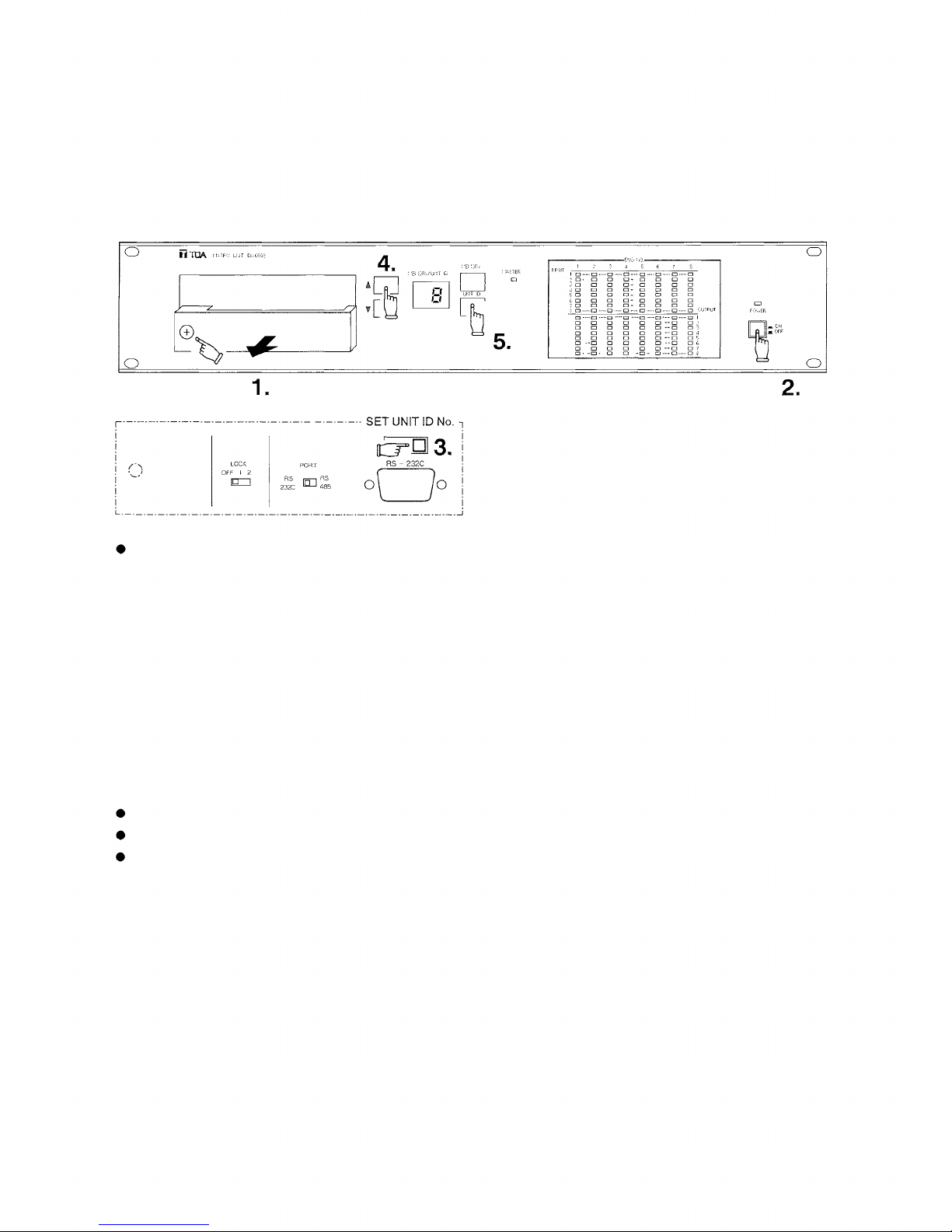
RS-232C communications port [RS-232C]
A 9-pin D-SUB connector for RS-232C communications. This connector can only be used when the
communications port selection switch located in the front pocket is set to "RS-232C". This connector is
connected in parallel to the D-SUB connector for RS- 232C in the pocket, and is valid only when controlling
a single unit. For details, refer to p.6 "6. PERSONAL COMPUTER CONNECTIONS".
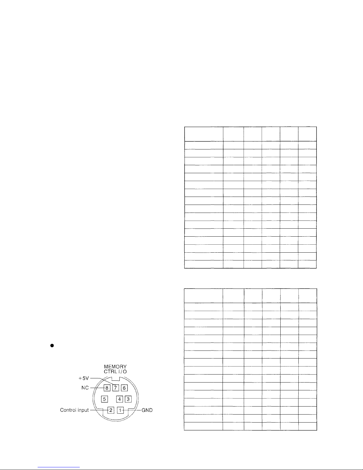
Memory I/O connector [MEMORY CTRL I/O]
This connector allows external remote pattern memory control, as well as output of memory selection status
to external equipment. Remote control is accomplished by make contact, and the 5 V logic output is used for
external output. For details, refer to p.9 "8. USING THE MEMORY I/O CONNECTOR".
Power inlet
Connect the power cord included with the unit to this inlet.
Ground loop break switch [GND]
This switch, when set to "LIFT" position, breaks a hum-generating ground loop formed when the unit is
connected to external components. Normally, set this switch to "NORM" position.
5