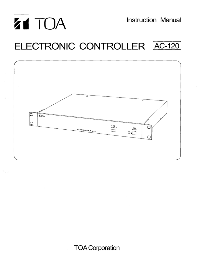
Toa AC-120 User manual

OPERATING INSTRUCTIONS
ELECTRONIC CONTROLLER AC-120
1. SAFETY PRECAUTIONS ........................... 2
2. GENERAL DESCRIPTION ......................... 3
3. FEATURES ................................................. 3
4. HANDLING PRECAUTIONS ...................... 3
5. NOMENCLATURE AND FUNCTIONS
Front ............................................................ 4
Rear ............................................................. 4
6. CONNECTIONS .......................................... 5
7. BLOCK DIAGRAM ..................................... 6
8. DIMENSIONAL DIAGRAM .......................... 7
9. SPECIFICATIONS ...................................... 8
Accessories ................................................. 8
ELECTRONIC CONTROLLER AC-120
ON
IN
POWER
LOWCUT
OFF
Thank you for purchasing TOA's Electronic Controller.
Please carefully follow the instructions in this manual to ensure long, trouble-free use of your equipment.
TABLE OF CONTENTS

2
When Installing the Unit
• Do not expose the unit to rain or an environment
where it may be splashed by water or other liquids,
as doing so may result in fire or electric shock.
• Use the unit only with the voltage specified on the
unit. Using a voltage higher than that which is
specified may result in fire or electric shock.
• Do not cut, kink, otherwise damage nor modify the
power supply cord. In addition, avoid using the
power cord in close proximity to heaters, and never
place heavy objects -- including the unit itself -- on
the power cord, as doing so may result in fire or
electric shock.
• The apparatus shall be connected to a mains
socket outlet with a protective earthing connection.
• The socket-outlet shall be installed near the
equipment and the plug (disconnecting device)
shall be easily accessible.
When the Unit is in Use
• Should the following irregularity be found during
use, immediately switch off the power, disconnect
the power supply plug from the AC outlet and
contact your nearest TOA dealer. Make no further
attempt to operate the unit in this condition as this
may cause fire or electric shock.
· If you detect smoke or a strange smell coming
from the unit.
· If water or any metallic object gets into the unit
· If the unit falls, or the unit case breaks
· If the power supply cord is damaged (exposure of
the core, disconnection, etc.)
· If it is malfunctioning (no tone sounds.)
• To prevent a fire or electric shock, never open nor
remove the unit case as there are high voltage
components inside the unit. Refer all servicing to
qualified service personnel.
• Do not place cups, bowls, or other containers of
liquid or metallic objects on top of the unit. If they
accidentally spill into the unit, this may cause a fire
or electric shock.
• Do not insert nor drop metallic objects or
flammable materials in the ventilation slots of the
unit's cover, as this may result in fire or electric
shock.
• Do not touch a power supply plug during thunder
and lightning, as this may result in electric shock.
When Installing the Unit
• Never plug in nor remove the power supply plug
with wet hands, as doing so may cause electric
shock.
• When unplugging the power supply cord, be sure
to grasp the power supply plug; never pull on the
cord itself. Operating the unit with a damaged
power supply cord may cause a fire or electric
shock.
• When moving the unit, be sure to remove its power
supply cord from the wall outlet. Moving the unit
with the power cord connected to the outlet may
1. SAFETY PRECAUTIONS
• Before installation or use, be sure to carefully read all the instructions in this section for correct and safe
operation.
• Be sure to follow all the precautionary instructions in this section, which contain important warnings and/or
cautions regarding safety.
• After reading, keep this manual handy for future reference.
Safety Symbol and Message Conventions
Safety symbols and messages described below are used in this manual to prevent bodily injury and property
damage which could result from mishandling. Before operating your product, read this manual first and
understand the safety symbols and messages so you are thoroughly aware of the potential safety hazards.
WARNING
Indicates a potentially hazardous situation which, if mishandled, could
result in death or serious personal injury.
Indicates a potentially hazardous situation which, if mishandled, could
result in moderate or minor personal injury, and/or property damage.
WARNING
CAUTION
CAUTION

3
cause damage to the power cord, resulting in fire or
electric shock. When removing the power cord, be
sure to hold its plug to pull.
• Avoid installing the unit in humid or dusty locations,
in locations exposed to the direct sunlight, near the
heaters, or in locations generating sooty smoke or
steam as doing otherwise may result in fire or
electric shock.
• Be sure to follow the instructions below when rack-
mounting the unit. Failure to do so may cause a fire
or personal injury.
· Install the equipment rack on a stable, hard floor.
Fix it with anchor bolts or take other arrangements
to prevent it from falling down.
· When connecting the unit's power cord to an AC
outlet, use the AC outlet with current capacity
allowable to the unit.
· The supplied rack-mounting screws can be used
for the TOA equipment rack only. Do not use
them for other racks.
When the Unit is in Use
• Contact your TOA dealer as to the cleaning. If dust
is allowed to accumulate in the unit over a long
period of time, a fire or damage to the unit may
result.
• Switch off the power, and unplug the power supply
plug from the AC outlet for safety purposes when
cleaning or leaving the unit unused for 10 days or
more. Doing otherwise may cause a fire or electric
shock.
2. GENERAL DESCRIPTION
The AC-120 Electronic Controller is designed for use with the F-122C and F-122CU2 Ceiling Speaker
Systems. It can also be used to enhance the sound quality of the F-500 series and F-600 series Speaker
Systems.
3. FEATURES
• Compact 1U rack size. (Mountable on an EIA equipment rack)
• Electrically-balanced I/O jacks. (Pin No. 3: HOT, No. 2: COLD, No. 3: GND)
• Output for subwoofers.
• A switch to cut low frequencies for the F-122C and F-122CU2 speakers.
4. HANDLING PRECAUTIONS
• The AC-120 can not be used for the outdoor speaker (splash-proof) models of the F-500 and F-600 series.
• To clean, be sure to first switch off the unit's power, then wipe with a dry cloth. When the unit gets very dirty,
use a cloth damped in a neutral cleanser. Never use benzene, thinner or chemically-treated cleaning cloth
because such volatile liquids could deform or discolor the unit.

4
ELECTRONIC CONTROLLER AC-120
ON
IN
POWER
LOW CUT
OFF
123 4
5. NOMENCLATURE AND FUNCTIONS
[Front]
1. Power switch [POWER]
Power is switched on and off with each
depression of this switch.
2. Power lamp
Lights when the power switch is set to ON.
3. Low cut switch [LOW CUT]
Pressing this switch when the equalizer selection
switch is set to "F-120C" position cuts low
frequencies.
4. Low cut indicator [IN]
Lights when the low cut switch is pressed.
HOT
CH 1
INPUT
CH 2CH 1
OUTPUT
LOW OUTEQ
CH 2
COLD
E
F-500/600
SERIES
F-120C
FG SG
6 7 8 9
10
5
[Rear]
5. Power cord
6. Ground terminal
Be sure to ground the unit.
When other components are connected, a ground
loop can be created, generating hum. In such
cases, remove a shorting piece.
Normally, use the unit with the shorting piece
attached.
7. Equalizer selection switch [EQ]
Set this switch to "F-120C" position if the F-122C
or F-122CU2 speaker is connected, and to "F-
500/600 SERIES" position if the F-500 series or F-
600 series speaker is connected.
8. Low frequency output jack [LOW OUT]
This electrically-balanced jack connects to a
subwoofer.
Cut-off frequency is 100 Hz (A slope of –12
dB/Oct)
9. Output jacks [OUTPUT CH 1, CH 2]
These electrically-balanced jacks connect to
power amplifiers.
10. Input jacks [INPUT CH 1, CH 2]
These electrically-balanced jacks are inputs for
external equipment.

5
6. CONNECTIONS
Speaker
Power Amplifier
CH 1
CH 2
CH 1
[When no subwoofer is used]
CH 2
Speaker
Electronic
Controller
AC-120
Mixer/
Preamplifier
Speaker
Power Amplifier
CH 1
CH 2
Low Out
CH 1
CH 2
Speaker
Subwoofer
Electronic
Controller
AC-120
Mixer/
Preamplifier
[When a subwoofer is used]
Notes
• Set the equalizer selection switch (EQ) depending on the type of connected speakers.
• The AC-120 cannot be used for the outdoor speaker (splash-proof) models of the F-500 series and F-600
series.

6
EBA
CH 1
INPUT
+4 dB*, 10 kΩ
CH 1
OUTPUT
+4 dB*, 600 Ω
CH 2
OUTPUT
+4 dB*, 600 Ω
EBA
LOW CUT
EQ
F-500/600
EQ
F-120C
LPF
SA
EBA
EBA
CH 2
INPUT
+4 dB*, 10 kΩ
* 0 dB = 0.775 Vrms
LOW CUT
EQ
F-500/600
EQ
F-120C EBA
7. BLOCK DIAGRAM

7
8. DIMENSIONAL DIAGRAM
ELECTRONIC CONTROLLER AC-120
ON
IN
POWER
LOW CUT
OFF
419 (16.5)
482.6 (19)
466 (18.35)
280 (11.02)
31.8 (1.25) 11.5 (0.45)
297.5 (11.71)
44 (1.73)
4-7 x 10.54 (0.28 x 0.41)
Unit: mm (inches)

133-12-080-8A
URL: http://www.toa.jp/
Traceability Information for Europe (EMC directive 2004/108/EC)
Manufacturer:
TOA Corporation
7-2-1, Minatojima Nakamachi, Chuo-ku, Kobe, Hyogo,
Japan
Authorized representative:
TOA Electronics Europe GmbH
Suederstrasse 282, 20537 Hamburg,
Germany
9. SPECIFICATIONS
* 0 dB = 0.775 Vrms
Note: The design and specifications are subject to change without notice for improvement.
• Accessories
Power Source AC mains, 50/60Hz
Power Consumption 9 W
Distortion Less than 0.05% (+4 dB*, 1 kHz)
Hum and Noise Less than –94 dB* (20 Hz – 20 kHz)
Input +4 dB*, 10 kΩbalanced phone jack,
Max input level: +20 dB*
Output CH out
+4 dB*, 600 Ω, balanced phone jack,
Max output level: +20 dB*
Low out
+4 dB*, 600 Ω, balanced phone jack,
Max output level: +20 dB*
Filter: 12 dB per octave
Cut off frequency: 100 Hz
Low cut Center frequency: 100 Hz, 6 dB cut (only for F-122C or F-122CU2)
Finish Panel: Aluminum, black
Dimensions 482.6 (w) x 44 (h) x 297.5 (d) mm (19 " x 1.73" x 11.71")
Weight 3.7 kg (8.16 lb.)
Rack mounting screw (5 x 20) .................... 4
Table of contents
Other Toa Controllers manuals
Popular Controllers manuals by other brands

LSIS
LSIS XGT Series user manual

Evco
Evco EVXS815 Installer manual

Eaton
Eaton EVER-Tap Installation, operation and maintenance instructions

SONBEST
SONBEST SM1635B2 user manual

Eaton
Eaton ELCM Series instruction sheet

Rockwell Automation
Rockwell Automation Allen-Bradley PLC-2/30 Assembly and installation manual