Toa AM-1 User manual

※量 産 用には使 用しないでください
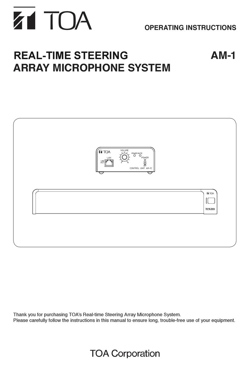
OPERATING INSTRUCTIONS
REALTIME STEERING
ARRAY MICROPHONE SYSTEM
AM-1
Thank you for purchasing TOA’s Real-time Steering Array Microphone System.
Please carefully follow the instructions in this manual to ensure long, trouble-free use of your equipment.

2
TABLE OF CONTENTS
1. IMPORTANT SAFETY INSTRUCTIONS ........................................... 3
2. SAFETY PRECAUTIONS ............................................................................. 4
3. GENERAL DESCRIPTION .......................................................................... 6
4. FEATURES ............................................................................................................ 6
5. HANDLING PRECAUTIONS ...................................................................... 6
6. NOMENCLATURE AND FUNCTIONS ................................................. 7
MICROPHONE ............................................................................................................ 7
CONTROL UNIT .......................................................................................................... 7
7. SYSTEM CONFIGURATION ....................................................................... 8
8. CONNECTIONS ................................................................................................. 8
9. GENERAL SETUP ............................................................................................ 9
10. SYSTEM SETTINGS ..................................................................................... 10
11. SPECIFICATIONS ........................................................................................... 11
MICROPHONE .......................................................................................................... 11
CONTROL UNIT ........................................................................................................ 11
Optional product ........................................................................................................ 11

3
1. IMPORTANT SAFETY INSTRUCTIONS
• Readtheseinstructions.
• Keeptheseinstructions.
• Heedallwarnings.
• Followallinstructions.
• Donotusethisapparatusnearwater.
• Cleanonlywithdrycloth.
• Donotinstallnearanyheatsourcessuchasradiators,heatregisters,stoves,orotherapparatus(including
ampliers)thatproduceheat.
• Donotdefeatthesafetypurposeofthepolarizedorgrounding-typeplug.
Apolarizedplughastwobladeswithonewiderthantheother.Agroundingtypeplughastwobladesanda
thirdgroundingprong.Thewidebladeorthethirdprongareprovidedforyoursafety.
Iftheprovidedplugdoesnottintoyouroutlet,consultanelectricianforreplacementoftheobsoleteoutlet.
• Protectthepowercordfrombeingwalkedonorpinchedparticularlyatplugs,conveniencereceptacles,and
the point where they exit from the apparatus.
• Onlyuseattachments/accessoriesspeciedbythemanufacturer.
• Unplugthisapparatusduringlightningstormsorwhenunusedforlongperiodsoftime.
• Referallservicingtoqualiedservicepersonnel.Servicingisrequiredwhentheapparatushasbeendamaged
inanyway,suchaspower-supplycordorplugisdamaged,liquidhasbeenspilledorobjectshavefalleninto
the apparatus, the apparatus has been exposed to rain or moisture, does not operate normally, or has been
dropped.

4
2. SAFETY PRECAUTIONS
• Beforeinstallationoruse,be suretocarefullyreadalltheinstructionsinthissectionforcorrectand safe
operation.
• Besuretofollowalltheprecautionaryinstructionsinthissection,whichcontainimportantwarningsand/or
cautions regarding safety.
• Afterreading,keepthismanualhandyforfuturereference.
Safety Symbol and Message Conventions
Safetysymbolsandmessagesdescribedbelowareusedinthismanualtopreventbodilyinjuryandproperty
damage which could result from mishandling. Before operating your product, read this manual rst and
understandthesafetysymbolsandmessagessoyouarethoroughlyawareofthepotentialsafetyhazards.
Indicatesapotentiallyhazardoussituationwhich,ifmishandled,could
result in death or serious personal injury.
Indicatesapotentiallyhazardoussituationwhich,ifmishandled,could
resultinmoderateorminorpersonalinjury,and/orpropertydamage.
WARNING
CAUTION
When Installing the Unit
• Do not expose the unit to rain or an environment
where it may be splashed by water or other liquids,
asdoingsomayresultinreorelectricshock.
• Use the unit only with the voltage specied on
theunit.Usingavoltagehigherthanthatwhichis
speciedmayresultinreorelectricshock.
• Do not cut, kink, otherwise damage nor modify
thepowersupplycord.Inaddition,avoidusingthe
powercordincloseproximitytoheaters,andnever
placeheavyobjects--includingtheunititself--on
the power cord, as doing so may result in re or
electric shock.
• Avoid installing or mounting the unit in unstable
locations, such as on a rickety table or a slanted
surface. Doing so may result in the unit falling
downandcausingpersonalinjuryand/orproperty
damage.
• Since the unit is designed for indoor use, do not
install it outdoors. When it gets wet, there is a
danger of electric shock.
• Theapparatusshallbeconnectedtoamainssocket
outletwithaprotectiveearthingconnection.
When the Unit is in Use
• Should the following irregularity be found during
use, immediately switch off the power, disconnect
the power supply plug from the AC outlet and
contact your nearest TOA dealer. Make no further
attempt to operate the unit in this condition as this
maycausereorelectricshock.
· If you detect smoke or a strange smell coming
from the unit.
· If water or any metallic object gets into the unit
· If the unit falls, or the unit case breaks
· Ifthepowersupplycordisdamaged(exposureof
thecore,disconnection,etc.)
· If it is malfunctioning.
• To prevent a re or electric shock, never open
norremovetheunitcaseandreferallservicingto
qualiedservicepersonnel.
• Do not place cups, bowls, or other containers of
liquid or metallic objects on top of the unit. If they
accidentallyspillintotheunit,thismaycauseare
or electric shock.
• Donottouchthepowersupplyplugduringthunder
and lightning, as this may result in electric shock.
• Theapparatusshallbeconnectedtoamainssocket
outletwithaprotectiveearthingconnection.
WARNING

5
When Installing the Unit
• Never plug in nor remove the power supply plug
with wet hands, as doing so may cause electric
shock.
• Whenunpluggingthepowersupplycord,besureto
graspthepowersupplyplug;neverpullonthecord
itself. Operating the unit with a damaged power
supplycordmaycauseareorelectricshock.
• The socket-outlet shall be installed near the
equipment and the plug (disconnecting device)
shall be easily accessible.
• Whenmovingtheunit,besuretoremoveitspower
supply cord from the wall outlet. Moving the unit
with the power cord connected to the outlet may
causedamagetothepowercord,resultinginreor
electricshock.Whenremovingthepowercord,be
sure to hold its plug to pull.
• Avoidinstallingtheunitinhumidordustylocations,
in locations exposed to the direct sunlight, near the
heaters, or in locations generating sooty smoke
or steam as doing otherwise may result in re or
electric shock.
When the Unit is in Use
• Makesurethatthevolumecontrolissettominimum
position before power is switched on. Loud noise
producedat high volume when poweris switched
on can impair hearing.
• UsethespeciedACadapterfortheunit.Notethat
theuseofotheradaptermaycauseare.
• If dust accumulates on the power supply plug or
in the wall AC outlet, a re may result. Clean it
periodically. In addition, insert the plug in the wall
outlet securely.
• Switchoffthepower,andunplugthepowersupply
plug from the AC outlet for safety purposes when
cleaningorleavingtheunitunusedfor10daysor
more.Doingotherwisemaycauseareorelectric
shock.
CAUTION

6
3. GENERAL DESCRIPTION
The AM-1 Real-time Steering Array Microphone System is a sophisticated microphone system, capable of
detecting a sound source location, and steering the microphone’s beam angle automatically in real-time to
capturethetargetedsoundmoreefciently.Inaddition,theuniqueuser-friendlyappandrmwareallowthe
user to monitor the status of the sound source, and make changes to its detailed setting parameters by using
an iPad™ or a PC.
4. FEATURES
• Themicrophone unitisequippedwith 8 microphoneelementsable to achievetheline arrayeffectwith a
narrowhorizontaldispersionangleof50degrees.
• Abletodetectasoundsourcelocationandsteerthemicrophone’sbeamangleautomaticallyinreal-timeto
focus on the targeted sound source.
• Thededicateduser-friendlyGUIisavailableforusewithaniPad™oraPC,whichallowsmonitoringofthe
sound source tracking status and setting of detail parameters.
• IthaseasymuteoperationwithaphysicalmuteswitchonthemicrophoneunitorthroughtheGUI.Themute
switchfunctionofthemicrophoneunitcanbedisabledthroughaGUIsetting.
• Twooutputs:adjustableanalogaudiooutputlevel,andAES/EBUdigitalaudiooutput.
5. HANDLING PRECAUTIONS
• Avoidinstallingtheunitinhumidordustylocations,inareasexposedtothedirectsunlight,nearheaters,or
in places generating sooty smoke or steam as doing otherwise may result in unit failure.
• Takecarenottodroptheunitontotheoornorbumpitagainstahardobjectastheunitcouldfail.
• Avoidusingamobiletelephonenearthemicrophoneinuse.Noisecouldbepickedup.
• Toclean,besuretorstpoweroffthecontrolunit,thenwipewithadrycloth.Whentheunitgetsverydirty,
useaclothdampenedinaneutralcleanser.Neverusebenzene,thinner,alcohol,orachemically-treated
cleansingclothbecausesuchvolatileliquidscoulddeformordiscolortheunit.

7
6. NOMENCLATURE AND FUNCTIONS
[MICROPHONE]
[CONTROL UNIT]
• Front • Rear
1. Microphone grill
For the unit to perform appropriately, this grill
shouldnotbecoveredwithanyobjects.
2. XLR connector
Connect to the MIC input terminal of the control
unit.
3. Mute indicator
Lights when the audio signal is muted by the mute
switchonthemicrophoneortheGUI.
4. Microphone status indicator
Lights when the unit is powered with the audio
signal being not muted.
5. Mute switch
Touch sensor switch to mute the output audio
signal.
1. Network connection terminal [10/100M]
Connecta10BASE-Tor100BASE-TXcompatible
network.(EthernetRJ45jack)
2. Volume control
Adjust the audio output level. Rotate the knob
clockwise to increase and counterclockwise to
decreasethevolume
3. Power indicator
Lights when the power switch is on.
4. Mute indicator
Lights when the audio signal is muted by the mute
switch on the microphone or in the software.
5. Power switch
To turn on the power, set this switch to the ON
position. To turn off the power, set this switch back
totheOFFposition.
6. DC inlet terminal
Connect the AC adapter.
*UsetheAD-246oritsequivalent.
7. MIC input terminal
Connect to the microphone unit with a shielded
twisted-paircable.(XLR-3-31equivalent)
8. AES/EBU digital output terminal
DigitaloutputterminalofAES/EBUformat.
(XLR-3-32equivalent)
9. Analog output terminal
Analogoutputterminal.(XLR-3-32equivalent)
10. Functional earth terminal
Groundthisterminal.
Note: Thisgroundisnotforprotectiveground.
11. Output level select switch
Adjusttheanalogoutputlevelfrom+4dBu,-10dBV,
or-50dBu.
12. Signal indicator
Lightswhentheinputsignallevelexceedsabout
-20dB.
1234 5
12 3 45
6 7 8 9
11
12

8
7. SYSTEM CONFIGURATION
8. CONNECTIONS
Microphone
Control Unit
AD-246
(Optional)
shielded twisted-pair cable (max.230 ft)
Control Unit
LAN-connected
switching HUB wireless router
Analog input of
mixer/amplifier
Digital input of
mixer/amplifier
AD-246
Optional AC adapter
PC iPad
or
Microphone Unit
[Front] [Rear]

9
9. GENERAL SETUP
Step 1. Conrmalldevicesareconnectedproperlywithspeciedcablesandconnectors.
Step 2. Adjusttheanalogoutputleveltomatchtheinputlevelofconnectedmixeroramplier.
Step 3. Makesurethevolumecontrolissettominimumposition,andthen turn on thecontrolunit’spower
switch.
Step 4. Whilespeakingtothemicrophonefromanappropriatedistance,adjusttheoutputlevelwiththevolume
control.

10
10. SYSTEM SETTINGS
ThedetailparametersettingsandmonitoringfeatureisavailableforusewithaPCoraniPad®,whichallows
the operation of the following key items.
[Real-time monitoring]
• Detectionofsoundsourcelocation
• Signallevelof8individualmicrophoneelements
[Parameter settings]
• Trackingrange(Horizontalangleanddistance)
• Trackingsensitivity
• Trackingspeed
• Gaincompensation
ON/OFF,Distanceadjustmentthreshold
• Duration(Timemonitoringofsoundsourcefootprint)
• DisablingofMUTEswitchfunctiononthemicrophone
• Outputgainleveladjustment
[Operation]
• MuteON/OFF
When using a PC, maintaining with these settings can
be performed via the PC’s browser. For an iPad®, the
dedicatedappis freeto download fromtheiTune®App
Store.
Dedicated GUI

11
11. SPECIFICATIONS
• MICROPHONE
Power Source 24VDC/200mA(suppliedfromControlUnit)
MaximumInputSoundLevel 100dBSPL(at20"distance)
S/NRatio 90dBormore(fromControlUnit)
FrequencyResponse 150-18,000Hz
DirectionalAngle Horizontal:50°(450-18,000Hz,Arraymode),180°(Cardioidmode)
Vertical:90°
Mute Switch Touch sensor
LEDIndicator Mute(red),Inoperation(blue)
Cable Shielded twisted-pair cable
Maximum Cable Length from
Control Unit 230ft(70m)
Dimensions 19.0"(W)x0.8"(H)x2.6"(D)(482x20x65mm)
Weight 2.4lb(1.1kg)
• CONTROL UNIT
Power Source 24VDC/400mA,fromanoptionalAD-246ACadapter
S/NRatio 90dBover
Microphone Input DedicatedinputforMicrophoneUnit,XLR-3-31equivalent
Audio Output Analog:+4dBu,-10dBV,-60dBu(selectable),XLR-3-32
equivalentDigital:AES/EBU24bit110Ω,XLR-3-32equivalent
Control Outputvolumecontrol,Outputleveladjustment
LEDIndicator Power(blue),Mute(red)
Ethernet 100/10Mbps(Category5,RJ45jack),TCP/IPHTTP
Dimensions 4.1"(W)x1.9"(H)x8.7"(D)(105x48x221mm)
Weight 1.3lb(0.6kg)
• Optional product
AD-246ACAdapter

URL:http://www.toa.jp/
633-22-037-20
Other manuals for AM-1
4
Table of contents
Other Toa Microphone System manuals