Toa RM-300MF User manual

TABLE OF CONTENTS, GENERAL DESCRIPTION
Update history
RM-300MF
1
No.833-71-185-80
FIREMAN'S MICROPHONE
RM-300MF
HS0907
GENERAL DESCRIPTION ......................................................................................................................... 1
NOTE ON REPAIR WORK SAFETY ......................................................................................................... 2
SPECIFICATIONS ..................................................................................................................................... 2
NOMENCLATURE AND FUNCTIONS ....................................................................................................... 3
WIRING DIAGRAM .................................................................................................................................... 5
SCHEMATIC DIAGRAMS
• CPU PCB (1/2) .................................................................................................................................... 6
• CPU PCB (2/2) .................................................................................................................................... 7
• SW PCB .............................................................................................................................................. 8
• EMG SW PCB ..................................................................................................................................... 8
• CONNECTOR PCB ............................................................................................................................ 9
• HANDMIC PCB ................................................................................................................................... 9
MOUNTING DIAGRAMS AND PARTS LIST
• CPU PCB ......................................................................................................................................... 10
• SW PCB ............................................................................................................................................ 11
• EMG SW PCB ................................................................................................................................... 11
• CONNECTOR PCB .......................................................................................................................... 11
• HANDMIC PCB ................................................................................................................................. 11
• PARTS LIST ..................................................................................................................................... 11
EXPLODED VIEW AND PARTS LIST ..................................................................................................... 12
TABLE OF CONTENTS
GENERAL DESCRIPTION
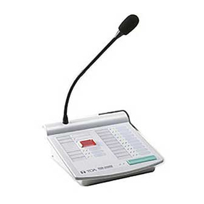
The RM-300MF Fireman's Microphone is designed for exclusive use with the VM-3000 Series. It is
equipped with an emergency activation key, permitting pre-recorded evacuation and alert announce-
ments to be activated, and microphone announcement to be made in emergency situations. By connect-
ing the RM-320F Fireman's Microphone Extension to the RM-300MF, the number of function keys can be
expanded. The zone selection or failure acknowledgment function can be assigned to such function
keys.

NOTE ON REPAIR WORK SAFETY SPECIFICATIONS2 2
RM-300MF
NOTE ON REPAIR WORK SAFETY
Follow the instructions below, both to prevent accidents when making repairs and to ensure post-repair
product safety.
Do not apply voltages other than those specified for the equipment or its compo-
nents.
Applying voltages other than the rated voltage could cause electrical breakdown or over-current, possi-
bly resulting in electric shock or fire. Power is supplied from the VM-3000 System.
After replacing parts, be sure to return the new parts and any other affected parts
to their previous configuration.
Check that all screws, parts, and wiring removed or changed during servicing have been restored to
their original states. Also, confirm that no damage has occurred around the serviced area.
Do not modify the design of circuit boards or other electronic elements.
Modifying circuit boards could cause electric shock or result in a fire hazard due to excessive heat
build-up. User modification automatically exempts the manufacturer from all personal and property lia-
bility caused by such modification, and the user who carried out such modification shall be solely
responsible for such accidents.
Since lead can become an environmental contaminant, this unit has been manufactured using solders
that contain no lead in the printed circuit board.
[While conventional solders are alloys of zinc and lead, lead-free solder is comprisend of an alterna-
tive alloy that contains no lead.]
NOTES
• Circuit boards using lead-free solder bear a lead-free solder designation. To maintain the integrity
of this designation, be sure to use lead-free solder when repairing such lead-free solder circuit
boards. Boards not marked with the lead-free solder designation may legally be serviced using
conventional solders.
• Because the melting point of lead-free solder (approximately 220°C) is 30°C-40°C higher than that
of conventional (lead-zinc alloy) solder, it tasks little longer to melt. It is recommended that a sol-
dering iron with controllable temperature be used and set to 20°C higher than would normally be
used with conventional solder.
Identifying printed circuit boards that use free-lead solder
Printed circuit boards that use lead-free solder have the following designation printed or stamped on
either side of the board.
• About lead-free solders
SPECIFICATIONS
24 V DC
(operating range: 15 – 40 V DC, supplied from the VM-3000 system)
120 mA (RM-300MF), 660 mA (with 3 RM-320Fs connected)
200 – 15kHz
1% or less
55 dB or more
Unidirectional dynamic microphone with talk key, compressor (on/off
switchable)
Microphone volume control, buzzer volume control
Main line: Shielded CPEV cable (each one pair of Audio line, Data line,
Power supply line) or Category 5 Shielded Twisted-Pair straight cable
for LAN (CAT5-STP), M3 screw terminal
Total 800 m
Max. 3 units
Emergency key, Evacuate key, Alert key, Emergency reset key,
CPU switch, Reset key
Power Indicator, Emergency Indicator, Communication Failure Indicator,
CPU OFF Indicator, Evacuation Announcement Indicator,
Alert Announcement Indicator, Emergency Reset Indicator,
Microphone In-Use Indicator, Emergency Broadcast Equipment In-Use
Indicator
–5°C to +45°C
5% to 95% RH (no condensation)
ABS resin, blueish gray (PANTONE 538 or its equivalent)
200 (w) x 215 (h) x 82.5 (d) mm
1.1 kg
Power Source
Current Consumption
Frequency Response
Distortion
S/N Ratio
Microphone
Volume Control
Connection Cable and Terminal
Maximum Cable Distance
No. of Connectable RM-320Fs
Operation
Indicator
Operating Temperature
Operating Humidity
Finish
Dimensions
Weight
Wall mounting bracket unit ................................... 1
Wall mounting screw ............................................ 2
Note: The design and specifications are subject to change without notice for improvement.
• Accessories

NOMENCLATURE AND FUNCTIONS3 3
RM-300MF
NOMENCLATURE AND FUNCTIONS
MIC SP CPU
OFF ON
EXTENSION
12
3
4
5
6
7 8
9
10
11
12
13 14
15 16
17
18
19
20
21
[Top] [Side]
22 23
[Bottom]
[Wall mount bracket unit (accessory)]
24 25
This microphone is designed to be used exclusively for emergency broadcasts made by firemen or other per-
sons when instructing building occupants to evacuate in emergency situations. It can activate the emergency
mode, start and stop automatic broadcasts of emergency announcements, reset emergency signals, and
make live microphone announcements in emergency situations. Operating the microphone’s CPU OFF
switch allows all-zone calls (simultaneous attenuator-free global calls) to go through. No general broadcasts
can be made. By connecting the RM-320F Fireman’s Microphone Extension to the RM-300MF Fireman’s
Microphone, the zone selection or failure indication/failure acknowledgment function can be enabled. Up to 3
RM-320Fs can be connected to the Fireman’s Microphone, expanding the available keys up to 20 per unit.
1. Power Indicator (green)
Lights when power is supplied to the unit.
2. Emergency Activation Switch / Emergency
Indicator (red)
Places the system in emergency mode while
illuminated. Also flashes when the emergency
mode is activated by external equipment. In this
event, if the switch is pressed to acknowledge
the emergency activation, it changes from flash-
ing to steady ON mode.
3. Buzzer
Sounds when a failure is detected or when the
emergency mode is activated.
* The buzzer sounds with the same tone in
either case.
4. Buzzer Volume Control [SP]
Adjusts the volume of the buzzer (3).
5. Microphone Volume Control [MIC]
Adjusts the volume of the emergency micro-
phone (20).
6. Microphone Holder
Holder for the emergency microphone (20).
7. CPU ON/OFF Switch [CPU]
Turns the CPU on and off. Normally set to the
ON position. Turning this switch off allows all-
zone calls by the CPU OFF function. To use the
CPU OFF function, Switch 8 of the DIP switch
(22) on the bottom surface must be set to ON.
8. Indication Label Holder
Write the name, purpose, etc. of the indicator
and key on a label and insert the label into the
holder from the top. Labels can be printed using
the setting software. (For more information, refer
to "Printing Remote Microphone Labels" in the
separate software manual.)
9.
Communication Failure Indicator (yellow/green)
Flashing Yellow
Indicates that a failure has been detected in
communications with the VM-3240VA and VM-
3360VA.
Lit Green
Indicates that the unit is in maintenance mode*.
In this event, the unit does not work. To return to
normal condition, set Switch 1 of the DIP switch
(22) on the bottom surface to OFF.
* Unit is placed in this mode if Switch 1 of DIP
switch (22) on the bottom surface is set to ON.
10. CPU OFF Indicator (red)
Lights when the unit is placed in CPU OFF
mode using the CPU OFF switch.
11. RM Reset Key
Resets the unit.
12. Evacuation Announcement Indicator (red)
Lights when Evacuation announcements are
made.
13. Evacuation Announcement Start Key
Plays the Evacuation announcement when in
emergency mode. When the RM-320F Fireman’s
Microphone Extension is used, the announce-
ment is broadcast over the zone(s) selected by
the RM-320F. Pressing this key without first
selecting the zones automatically makes an all-
zone call. To stop the Evacuation announcement,
hold down the key for 3 seconds.
14. Alert Announcement Indicator (red)
Lights when an Alert announcement is made.
15.
Alert Announcement Start Key / Lamp Test
Key
Plays the Alert announcement when in emer-
gency mode. When the RM-320F Fireman’s
Microphone Extension Unit is used, the
announcement is broadcast over the zone(s)
selected by the RM-320F. Pressing this key with-
out first selecting the zones automatically makes
an all-zone call. To stop the Alert announcement,
hold down this key for 3 seconds. Pressing this
key during general broadcast mode allows a lamp
test to be conducted.
16. Emergency Reset In-Progress Indicator (red)
Remains lit while the Emergency Reset key (17)
is pressed.
17. Emergency Reset Key
Terminates emergency broadcasts to return to
general broadcasts.
18. Emergency Microphone In-Use Indicator
(green)
Lights when the Emergency Microphone (20) is
used for broadcasts.

NOMENCLATURE AND FUNCTIONS4 4
RM-300MF
19. External Emergency Equipment In-Use
Indicator (orange / green)
Flashes when external emergency equipment is
used for broadcasts.
Orange: Indicates the mode that disables broad-
casts from the unit.
Green: Indicates the mode that allows the unit to
interrupt broadcasts from external equipment.
20. Emergency Microphone
After the emergency mode is activated, press
the Talk key located on the side of the micro-
phone to make an all-zone call or emergency
broadcast over the selected zones (the RM-
320F is required for zone selection).
21. RM-320F Connector
Connect the RM-320F Fireman’s Microphone
Extension Unit to this connector.
22. DIP Switch
Used to set the unit ID number and equipment
functions.
Switch 1 [MAINTENANCE]
Always set this switch to the OFF position.
Default setting: OFF
Note
If this switch is set to ON, the unit is placed in
the maintenance mode and the front panel-
mounted Communication Failure indicator (9)
lights green, causing the unit not to work.
Switches 2 – 4
Not used.
Default setting: OFF
Switch 5 [UNIT ID]
Sets the ID number of the Fireman’s
Microphone.
Default setting: ON
Switch 6 [COMPRESSION]
Enables/disables compression.
Default setting: ON
Switch 7 [TERMINATION]
Sets the RM-300MF Fireman’s Microphone that
functions as a terminating unit.
Default setting: OFF
Switch 8 [CPU OFF]
Enables/disables the CPU OFF function.
Default setting: ON
23. Relay Connector
Connects to the relay connector (24) of the wall
mount bracket unit (accessory).
24. Relay Connector
Connect the cable from the RM-300MF Fireman’s
Microphone to this connector.
25. Screw Terminal Block
RM Communication Line [DATA (+), DATA (–)]
A control/communication line between the RM-
300MF Fireman’s Microphone and the VM-
3240VA or VM-3360VA.
Audio Output Line [AUDIO OUT H/C]
Audio output line from the RM-300MF Fireman’s
Microphone to the VM-3240VA or VM-3360VA.
DC Power Supply Input [DC IN 24V +/-]
Power supply line from the VM-3240VA or VM-
3360VA to the RM-300MF Fireman’s
Microphone.
Shield [SHIELD]
Control line used by the VM-3240VA or VM-
3360VA for confirmation of RM-300MF connec-
tions. Ensure that at least one shield is connect-
ed.

1
2
3
4
CPU PCB
HANDMIC
PCB
CONNECTOR PCB
EMG SW PCB
SW PCB
WIRING DIAGRAM
1
A
B
C
D
E
F
G
H
23 654 789 11121310
I
5 5
RM-300MF
WIRING DIAGRAM
Ref.No. Part Code Description
1 123-39-730-20 CONNECTION CABLE W/PLUG 3P
2 124-04-316-90 FLAT CABLE, 19T83(200)P1.25
3 123-49-486-50 CONNECTION CABLE W/PLUG 8P
4 123-39-377-70 CONNECTION CABLE, W/PLUG 3P
· HARNESS LIST
*The parts not listed are not supplied.
Please refer to page 9
Please refer to page 8
Please refer to page 6-7
Please refer to page 8
Please refer to page 9

SCHEMATIC DIAGRAMS
1
A
B
C
D
E
F
G
H
23 654 789 11121310
I
6 6
RM-300MF
To EMG SW PCB
CN301
To SW PCB
CN201
To CONNECTOR PCB
CN501
RM-320F Connector
CPU ON/OFF Switch
DIP Switch
• CPU PCB (1/2)
SCHEMATIC DIAGRAMS
RESISTANCE VALUES IN OHMS. INDUCTANCE VALUES IN HENLY.
ALL RESISTORS 1/16W UNLESS OTHERWISE DESIGNATED.
CAPACITANCE VALUES IN FARADS, 50V UNLESS OTHERWISE DESIGNATED.
CIRCUITS ARE SUBJECT TO CHANGE WITHOUT NOTICE FOR FURTHER IMPROVEMENT.

SCHEMATIC DIAGRAMS
1
A
B
C
D
E
F
G
H
23 654 789 11121310
I
7 7
RM-300MF
To HANDMIC
Buzzer Volume
Control
Buzzer
Buzzer
Buzzer
Microphone Volume
Control
• CPU PCB (2/2)
RESISTANCE VALUES IN OHMS. INDUCTANCE VALUES IN HENLY.
ALL RESISTORS 1/16W UNLESS OTHERWISE DESIGNATED.
CAPACITANCE VALUES IN FARADS, 50V UNLESS OTHERWISE DESIGNATED.
CIRCUITS ARE SUBJECT TO CHANGE WITHOUT NOTICE FOR FURTHER IMPROVEMENT.

SCHEMATIC DIAGRAMS
1
A
B
C
D
E
F
G
H
23 654 789 11121310
I
8 8
RM-300MF
To CPU PCB
CN3
Power Indicator
Communication
Failure Indicator
CPU OFF Indicator
Evacuation
Announcement
Indicator
Alert Announcement
Indicator
Emergency Reset
In-Progress Indicator
External Emergency
Equipment In-Use
Indicator
Emergency Microphone
In-Use Indicator
Emergency Reset Key
Alert Announcement
Start Key / Lamp Test Key
Evacuation
Announcement
Start Key
RM Reset Key
• SW PCB
To CPU PCB
CN2
Emergency
Activation Switch
• EMG SW PCB
RESISTANCE VALUES IN OHMS. INDUCTANCE VALUES IN HENLY.
ALL RESISTORS 1/16W UNLESS OTHERWISE DESIGNATED.
CAPACITANCE VALUES IN FARADS, 50V UNLESS OTHERWISE DESIGNATED.
CIRCUITS ARE SUBJECT TO CHANGE WITHOUT NOTICE FOR FURTHER IMPROVEMENT.
RESISTANCE VALUES IN OHMS. INDUCTANCE VALUES IN HENLY.
ALL RESISTORS 1/16W UNLESS OTHERWISE DESIGNATED.
CAPACITANCE VALUES IN FARADS, 50V UNLESS OTHERWISE DESIGNATED.
CIRCUITS ARE SUBJECT TO CHANGE WITHOUT NOTICE FOR FURTHER IMPROVEMENT.

SCHEMATIC DIAGRAMS
1
A
B
C
D
E
F
G
H
23 654 789 11121310
I
9 9
RM-300MF
To CPU PCB
CN5
To VM-3000
Screw Terminal Block
• CONNECTOR PCB • HANDMIC PCB
RESISTANCE VALUES IN OHMS. INDUCTANCE VALUES IN HENLY.
ALL RESISTORS 1/16W UNLESS OTHERWISE DESIGNATED.
CAPACITANCE VALUES IN FARADS, 50V UNLESS OTHERWISE DESIGNATED.
CIRCUITS ARE SUBJECT TO CHANGE WITHOUT NOTICE FOR FURTHER IMPROVEMENT.
RESISTANCE VALUES IN OHMS. INDUCTANCE VALUES IN HENLY.
ALL RESISTORS 1/16W UNLESS OTHERWISE DESIGNATED.
CAPACITANCE VALUES IN FARADS, 50V UNLESS OTHERWISE DESIGNATED.
CIRCUITS ARE SUBJECT TO CHANGE WITHOUT NOTICE FOR FURTHER IMPROVEMENT.

MOUNTING DIAGRAMS AND PARTS LIST
1
A
B
C
D
E
F
G
H
23 654 789 11121310
I
10 10
RM-300MF
MOUNTING DIAGRAMS AND PARTS LIST
• CPU PCB (Part Code : 700-04-438-80)
RM-320F
Connector
DIP Switch
(Viewed from parts mounting side)
SW2
BZ101BZ102
BZ103
VR102VR101
CPU ON/OFF SwitchMicrophone
Volume
Control
Buzzer
Volume
Control
Buzzer
BuzzerBuzzer
(Viewed from Conductor side)
The parts marked with red designators on the mounting diagrams can be supplied.
Position the mouse pointer over the part or click it to display its part number and name.
Note that they are not displayed if the cursor is in zoom-in or zoom-out mode.

MOUNTING DIAGRAMS AND PARTS LIST
1
A
B
C
D
E
F
G
H
23 654 789 11121310
I
11 11
RM-300MF
• EMG SW PCB (Part Code : 700-04-442-70)
Emergency
Activation Switch
• SW PCB (Part Code : 700-04-439-50)
Evacuation Announcement
Start Key
Alert Announcement
Start Key / Lamp Test Key
Emergency Reset Key
RM Reset Key
Power Indicator
Communication
Failure Indicator
CPU OFF Indicator
Evacuation
Announcement Indicator
Alert Announcement
Indicator
Emergency Reset
In-Progress Indicator
External Emergency
Equipment In-Use Indicator
Emergency Microphone
In-Use Indicator
• CONNECTOR PCB (Part Code : 700-04-440-30)
SHIELD
SHIELD
DATA(–)
DATA(+)
AUDIO OUT
DC IN
24V +
–
DC IN
24V +
–
H
C
• HANDMIC PCB (Part Code : 700-04-441-40)
Designator Part Code Description
BZ101 110-06-020-40 SOUNDER, PKM13EPY-4000
BZ102 110-06-020-40 SOUNDER, PKM13EPY-4000
BZ103 110-06-020-40 SOUNDER, PKM13EPY-4000
C40 113-42-094-60 CAPACITOR, LXZ 6.3VB 3300M
C44 113-42-094-60 CAPACITOR, LXZ 6.3VB 3300M
C59 113-42-093-90 CAPACITOR, 50VB 220M J20
C60 113-42-093-90 CAPACITOR, 50VB 220M J20
C61 113-42-093-90 CAPACITOR, 50VB 220M J20
CN1 123-36-207-60 CONNECTOR S08B-XASK-1
CN2 123-26-276-90 CONNECTOR, B3B-EH-A
CN3 123-36-204-30 CONNECTOR 19FE-BT-VK-N
CN5 123-36-207-60 CONNECTOR S08B-XASK-1
CN6 124-04-318-70 TERMINAL, P-820
CN101 123-26-277-20 CONNECTOR, B4B-EH-A
CN201 123-36-205-20 CONNECTOR, 19FE-ST-VK-N
CN301 123-39-730-20 CONNECTION CABLE W/PLUG 3P
CN403 123-39-377-70 CONNECTION CABLE, W/PLUG 3P
CN501 123-36-207-60 CONNECTOR S08B-XASK-1
CN502 124-02-785-50 TERMINAL, DT-25-A01W-10
D22 111-04-161-30 POLYSWITCH, RXE185
M4 111-06-783-90 IC, AQV210E
M6 101-08-464-40 HEATSINK, DC/DC-IC VX2000
M105 111-06-851-90 IC, NJM2073D
PJ501 111-04-118-1R PTH8L07BD100N2B510
PJ502 111-04-118-1R PTH8L07BD100N2B510
SW1 115-51-138-90 SWITCH, DIP, EAM108L (E)
SW2 115-12-242-00 SWITCH, SLIDE SSSF012SA3-NT
SW201 115-14-476-1X SWITCH, TACT SFKHML2420-NT
SW202 115-14-486-80 SWITCH, B3F-5001
SW203 115-14-486-80 SWITCH, B3F-5001
SW204 115-14-486-80 SWITCH, B3F-5001
SW301 123-05-319-80 SOCKET, SW 50-015-01
T1 114-03-080-70 INPUT TRANS,IT-423
VR101 112-06-934-00 POT.,6G-6-401KW 10KOHM(B) ADJ
VR102 112-06-934-00 POT.,6G-6-401KW 10KOHM(B) ADJ
X1 115-46-082-90 X-TAL, AT-49 9.8304MHZ
Z501 111-04-115-20 ABSORBER,ERZ-V10D820
Z502 111-04-115-20 ABSORBER,ERZ-V10D820
Z503 111-04-115-20 ABSORBER,ERZ-V10D820
Z504 111-04-115-20 ABSORBER,ERZ-V10D820
Z505 111-04-115-20 ABSORBER,ERZ-V10D820
Z506 111-04-115-20 ABSORBER,ERZ-V10D820
Z507 111-04-115-20 ABSORBER,ERZ-V10D820
• PARTS LIST
*The parts not listed are not supplied.

1
5
8
3
6
7
7
2
12
13
12
19
4
9
10
17
11
14
15
18 18
16
11
ACCESSORY
AA
BB
B
B
B
B
B
B
D
D
E
C
B
CONNECTOR PCB
CPU PCB
EMG SW PCB
CASE ASSY.
SW PCB
The microphone unit comes with a connector housing (EHR-4).
Caution
EXPLODED VIEW AND PARTS LIST
1
A
B
C
D
E
F
G
H
23 654 789 11121310
I
12 12
RM-300MF
EXPLODED VIEW AND PARTS LIST
Ref.No. Part Code Description
1 Z3292 CASE ASSY, UPPER RM300MF
2 101-11-092-50 DOST COVER,RM200XF
3 102-15-428-70 HOLDER,MICROPHONE RM200XF
4 102-32-327-8A UNDER COVER, RM300MF
5 121-01-859-70 COVER,REC TANGLE180° 50-011-12
6 121-01-860-90 KNOB, RM200XF
7 Z3302 MIC ASSY, RM300MF
8 115-14-485-70 SWITCH, P16LMT1-1ABHR(RED)
9 102-32-328-3A BRACKET, TERMINAL RM300MF W/S
10 102-32-326-50 BRACKET, WALL RM300MF
11 123-49-486-50 CONNECTION CABLE W/PLUG 8P
12 124-04-316-90 FLAT CABLE, 19T83(200)P1.25
13 123-39-730-20 CONNECTION CABLE W/PLUG 3P
14 700-04-438-80 PCB ASSY, CPU RM300MF
15 700-04-439-50 PCB ASSY, SW RM300MF
16 700-04-442-70 PCB ASSY, EMG SW RM300MF
17 700-04-440-30 PCB ASSY, CONNECTOR RM300MF
18 C06-31-010-20 B.H. SCREW, 4*25 TAPPING(1)
19 D15-44-013-70 FILTER, A8H150285070
· SCREWS
Ref.No. Part Code Description
A 106-61-618-30 B.H. SCREW, 3*12 B-TIGHT
B 106-61-615-40 B.H. SCREW, 3*8 B-TIGHT
C C06-73-004-00 LOCK WASHER M4 EXTERNAL
D C06-02-001-80 P.H. SCREW, M3*8
E 106-61-614-50 B.H. SCREW, M3*6
*The parts not listed are not supplied.
Ferrite core
Ferrite core
Ferrite core
Connector housing
Connector housing
Connector housing
Microphone cable
Microphone cable
Microphone cable
MIC ASSY's cable connection
Run the free end of the curled cable of the MIC
ASSY through the cable hole in the upper case
and then the ferrite core inside the case. Then
attach the connector housing (EHR-4) to the
cable end.
Moving the mouse pointer over the circled number or alphabet, or clicking it
on the exploded view pops up indications showing its part number and name.
Note that they are not displayed if the cursor is in zoom-in or zoom-out mode.
Table of contents
Other Toa Microphone System manuals
Popular Microphone System manuals by other brands

Shure
Shure PSM 900 user guide

Leuze electronic
Leuze electronic DDLS 508 Original operating instructions

Nissindo
Nissindo LX-2020 G2 Operation manual

Communications Specialties
Communications Specialties Pure Digital FIBERLINK 3800 Series user manual

Shure
Shure ANTENNA SETUP Guide

AKG
AKG HT 40 PRO User instructions