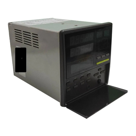
Toho Electronics TTX-800 User manual

- 1 -
TOHO ELECTRONICS INC.
Operation Manual(Communication Edition)
(TOHO Protocol, MODBUS)
Model:TTX-800
Name:2ch Module-typeController
4D-6607-A

- 2 -
Thankyouverymuchfor purchasingTTX-800.
Kindlyreadthisoperation manualforproperusage.
Table of Contents
1. BeforeUsingtheProduct······································································· - 3 -
1.1 AbouttheOperationManual ······························································· - 3 -
1.2 Things theCommunicationFunctionCan Do···················································· - 3 -
1.3 Position(Priority)ofCommunication·························································· - 3 -
1.4 SettingstoBeMadePriortoCommunication ··················································· - 3 -
2. SettingtheMODBUSCommunication ····························································· - 4 -
2.1 Outline ················································································ - 4 -
2.2 DetailedSettingsoftheCommunicationSettingMode ············································ - 5 -
3. MODBUSCommunicationControl································································ - 7 -
3.1 Communication Procedures ································································ - 7 -
3.2Kinds ofMessage ········································································ - 7 -
3.3 ExplanationofMODBUSRTUCommunication ·················································· - 8 -
3.4 ExplanationofMODBUSASCII Communication················································· - 13 -
4. Specifications··············································································· - 18 -
4.1 TypeofCommunicationStandard··························································· - 18 -
4.2 Communication Specifications ····························································· - 18 -
5. Wiring ···················································································· - 19 -
6. ListofIdentifiers(Codes) ······································································ - 20 -
7. ListofASCIICodes ··········································································· - 27 -

- 3 -
1. BeforeUsingtheProduct
1.1 AbouttheOperationManual
Thismanualexplainsthecommunicationfunctionofthe TTX-800(hereinafterreferredtoasthe“Product”).
1.2 Things theCommunicationFunctionCanDo
The unitisequippedwith RS-485fordatacommunicationwiththehostcomputer,whichallowsusers towriteand read
toitems ofthis productthataredescribedin“6.ListofIdentifiers(Codes),” such as“To change,start,orstop itemsthat
canbeoperatedthroughfrontkeys”and“Toreadtheinformationthatcanbedisplayedonthedisplaysection.”
Provided,however,that sincetheRAMofthisproductisusedduringthereading/writingofdata through ordinary
command, datathatwas writtenwillbereplacedbythepreviousdata(datathatissavedinEEPROM)ifthepoweris
turned OFFand then turned ON.
Tosavethe writtendataintoEEPROM ofthisproduct, executethesaverequest message.
(See“3.3.4”and“3.4.4,” ThingstobeNotedDuringCommunication)
Furthermore,unnecessarysettingitems,such asitemsthatarerelated totheunattachedoption,willnotbereadand
written.
1.3 Position(Priority)ofCommunication
Thisproductallowstheusertochangedataandparametersthrough thekeyeven duringoperationunder
communicationmode.
Changeofsettingsofdataandparametersviacommunicationwillbedisabled whiletheproductisoperatedunder RO
(ReadOnly).
(Provided,however, thatswitching ofcommunicationmodeispossible.)
1.4 SettingstoBeMadePriortoCommunication
Severalsettingsneedtobemadetothisproductforittoperformacommunicationfunction.See
“2. SettingtheMODBUS Communication.”

- 4 -
2. SettingtheMODBUSCommunication
2.1 Outline
Initialsettingsneed tobemadetotheproduct forittoperformacommunicationfunction.Settingshallbedonebykeysat
the frontside.
Followtheprocedureshownbelowtonavigatebetween settingscreens.See theUser’s Manualoftheproductfordetails.
Whenthesettingisdone,presstheMODEkeyfor morethan twosecondstoreturntooperationmode.
Communicationsetting modeisasettingmodethatiscommonfor channels. Itcan changethecommunicationsetting
withthefollowingoperation regardlessoftheselectionofCH:
Eachparametershownaboveistheinitialvalue.

- 5 -
2.2 Detailed Settings oftheCommunication SettingMode
2.2.1 Settingofthe CommunicationProtocol
PV
Pleasesetthecommunicationprotocol.
SV
InitialValue
Settings
:
Modbus(RTU)
:
Modbus(ASCII)
2.2.2 DataLength
PV
Pleasesetthedata length.
SV
InitialValue
Settings
:
7bits
:
8bits
2. 2. 1. Thiscanbeset onlyifthesettingofthecommunicationprotocolis“2”
2.2.3 Parity Check
PV
Pleasesettheparitycheck.
SV
InitialValue
Settings
:
OFF
:
Odd
:
Even
2.2.4 Stop BitLength
PV
Pleasesetthestop bitlength.
SV
InitialValue
Settings
:
1bit
:
2bits

- 6 -
2.2.5 Settingofthe Communication Speed
PV
Pleasesetthecommunicationspeed.
SV
InitialValue
Settings
:
1200bps
:
2400bps
:
4800bps
:
9600bps
:
19200bps
:
38400bps
2.2.6 CommunicationAddress
PV
Pleasesetthe communication address.
SV
InitialValue
Settings
SettingRange
:
1~247
The communication addressofCH2is“Communication
Address +1”
Ifitissetto“247,” theaddress ofCH2is“1.”
2.2.7 Response DelayTime
PV
Pleasesettheresponse delaytime.
SV
InitialValue
Settings
SettingRange
:
0~250 ㎳
Set thetimetotakefortheupper computerto completethereceivingofthe“requestmessage,” open theline, andget
readyfor thenextinput.
*Communicationmaynotbeperformed properly iftheresponsedelay time is tooshort.
*In actualoperation,the processingtimeoftheproductwillbeadded totheresponsedelaytime.
2.2.8 SwitchingoftheCommunicationMode
PV
Pleasesettheswitchingofthecommunicationmode.
SV
InitialValue
Settings
:
CommunicationRisavailable
:
CommunicationRWis available
Onlythis settingwillallowR/Wofcommunicationeven during“RO.”

- 7 -
3. MODBUSCommunicationControl
3.1 Communication Procedures
Thisproductreturnsthe“responsemessage”asareplytothe“requestmessage”that willbesentbytheuppercomputer.
Therefore, thetransmissionwillneverbeinitiated bythis product.
3.2 KindsofMessage
■Kindsofmessagecanbebrieflyclassified intothe following:
■Dataisin binaryduringMODBUS RTUmode.
■Inthecaseofthe MODBUSASCIImode,all codeswill beexpressedinASCIIcode.
■To codetheprogramfortheuppercomputer,see“6.List ofIdentifier(Codes)”and“7. ListofASCIICodes.”
■Thisproduct willnotsavethe dataunlessthesaverequestmessageisreceived.
TokeepthedataforthenextpowerON,sendthesaverequestmessage.
See "3.3.4.1 TimingofTransmission."
See "3.3.4.2 RequestInterval."

- 8 -
3.3 ExplanationofMODBUSRTUCommunication
3.3.1 StructureofMODBUSRTURequestMessage(DataTransmission fromtheUpperComputertoThisProduct)
■See“3.3.3 ExplanationofMODBUSRTU Codes”forcodesa)tog).
3.3.1.1 StructureofReadRequestMessage
a)
SlaveAddress
01H
b)
FunctionCode
03H
c)
RegisterAddress
Upper
00H
Firstregisteraddress
Lower
00H
d)
NumberofRegisters
Upper
00H
2(fixed)
※Except for communication monitor
registeraddress
Lower
02H
e)
CRC-16
Lower
C4H
Upper
0BH
3.3.1.2 StructureofWriteRequest Message
a)
SlaveAddress
01H
b)
FunctionCode
10H
c)
RegisterAddress
Upper
01H
Firstregisteraddress
Lower
00H
d)
NumberofRegisters
Upper
00H
2(fixed)
Lower
02H
f)
NumberofBytes
04H
NumberofRegistersx2
g)
DatafortheFirstRegister
(LowerWord)
Upper
00H
③
Data structure is ①②③④H.
(① represents 1 byte)
Lower
00H
④
DatafortheFirstRegister
(Upper Word)
Upper
00H
①
Lower
00H
②
e)
CRC-16
Lower
FEH
Upper
3FH
3.3.1.3 StructureofSave Request Message
a)
SlaveAddress
01H
b)
FunctionCode
10H
c)
RegisterAddress
Upper
09H
Firstregisteraddress
Lower
0CH
d)
NumberofRegisters
Upper
00H
2(fixed)
Lower
02H
f)
NumberofBytes
04H
NumberofRegistersx2
g)
DatafortheFirstRegister
(LowerWord)
Upper
00H
Dataforsavingthe settingis
optional.
Lower
00H
DatafortheFirstRegister
(Upper Word)
Upper
00H
Lower
00H
e)
CRC-16
Lower
E8H
Upper
E2H

- 9 -
3.3.2 StructureoftheMODBUSRTUResponseMessage(DataTransmissionfromThisProducttoUpper Computer)
■See“3.3.3 ExplanationofMODBUSRTU Codes“forcodesa)toh).
3.3.2.1 ResponseMessageforReadRequestMessage
a)
SlaveAddress
01H
b)
FunctionCode
03H
f)
NumberofBytes
04H
NumberofRegistersx2
g)
DatafortheFirstRegister
(LowerWord)
Upper
0AH
③
Data structure is ①②③④H.
(① represents 1 byte)
Lower
A1H
④
DatafortheFirstRegister
(Upper Word)
Upper
00H
①
Lower
00H
②
e)
CRC-16
Lower
A8H
Upper
09H
3.3.2.2 ResponseMessageforWrite/SaveRequestMessage
a)
SlaveAddress
01H
b)
FunctionCode
10H
c)
RegisterAddress
Upper
01H
Firstregisteraddress
Lower
00H
d)
NumberofRegisters
Upper
00H
2(fixed)
Lower
02H
e)
CRC-16
Lower
40H
Upper
34H
3.3.2.3 ResponseMessagefortheError
a)
SlaveAddress
01H
b)
FunctionCode
83H
← In case of error, the value that consists of
the function code of request message +80H
willbeset.
h)
ErrorNumber
03H
e)
CRC-16
Lower
01H
Upper
31H

- 10 -
3.3.3 Explanation ofMODBUSRTUCodes
■Thefollowingcodesfroma)SlaveAddress,b)FunctionCodeuptoh)ErrorCodewillbeexpressedin 8-bit binary:
a)SlaveAddress
Thisistheaddressofthedevicethat willbecommunicated bytheupper computer (this product).
The addressintheresponsemessagefromthis productindicatesthesourceofthe responsemessage.
b)FunctionCode
Enterthecode 03Hor10H.
・03H:Ifthedatais tobereadfromthis product
・10H:Ifthedataistobewritten orsavedintothisproduct
c)Register Address
Specifiestheposition ofdatatobereadorwrittenwithtwobytes.
See“6. List ofIdentifiers (Codes)”forthe addressofeach command.
d)NumberofRegisters
Specifiesthenumberofregistersthat write.
Sincethenumberofregisters ofthis productisfixedto 2,setitto“0002H.”
e)CRC-16
Thisisanerrorcheckingcode forthe detection ofa possibleerror inthemessage.Itsends CRC-16(CyclicRedundancy
Code).
The generatingpolynomialof CRC-16thatisused inthis productisX16 +X15 +X2+1.
The lowerbytebeforetheupperbyteistobeattachedatthe endofthemessage.
f)NumberofBytes
Specifiesthenumberofregistersthatreadand writex2.
Sincethenumberofregisters ofthis productis2(fixed),set“04H.”
g)DataSection
Specifiesthedata tobewritteninto theregister.Data is fourbytes(fixed).
Ifthedatacontainsa decimalpoint,setthenumericvaluethatignoresthedecimalpoint.
Datathatisenclosed inparentheses isthevaluethatwillbeusedintheactualmessage tobesent.See
“3.3.1 StructureoftheMODBUSRTURequestMessage(DataTransmissionfromUpperComputertoThisProduct)”for details.
■Incaseofnumericaldata
ContentsofCommunication
HEXData
PV=1200.0(℃)
00002EE0h(2EE00000)
SV =-10.00(℃)
FFFFFC18h(FC18FFFF)
■ASCII code will be written in case of character data (□ means space).
ContentsofCommunication
HEXData
PriorityScreen0-1=☐INP
20494E50h(4E502049)
PriorityScreen0-2=☐☐P1
20205031h(50312020)

- 11 -
h)ErrorNumber
Ifthereisanerrorinthemessagethat wassentbytheupper computer, theerror numberwillbeincludedinthe
“responsemessage”ofthisproductforthereply.
Contentsand classificationoferrorsarethefollowing:
ErrorNumber
Descriptionoferrorsinthe“Request Message”thatwasreceivedbythis product
01
Receivedanunsupported function code
02
Receivedanunspecified address
03
Numericalvaluedataisoutofthe“settingrangethatis specifiedindividuallybythesetting
item”

- 12 -
3.3.4 Thingsto Be NotedDuringMODBUSRTU Communication
3.3.4.1 Timing of Transmission
UponusingRS-485,setenoughresponsedelaytimeto ensurecommunication(sending/receiving) withtheupper
computer.
Seethefigure“3.1Communication Procedures.”
3.3.4.2 RequestInterval
If “requestmessage”istobesentcontinuouslybytheuppercomputer,wait foratleast2msecs.fromthearrivalofthe
“responsemessage”fromthisproductbeforesending thenextrequestmessage.
3.3.4.3 Conditions for Response
Thisproductwill notreturn the“responsemessage”ifthereisatime intervalofmorethan 3.5characters between data
thatcomprisethe“request message”since itcannotidentify thesedataasone whole“requestmessage.”
Therefore, althoughthereis an errorinthe“request message,” a “responsemessage”with theerrornumber(response
for theerror) willnotbereturned unlesstheabove conditionismet.
Therefore, theuppercomputershouldresendthenecessary “request message”ifthe“responsemessage”isnotreturned
withinthereasonabletime.
At atimeintervalofmorethan 3.5characters, this productclears allcharacters thatwerereceivedpriortothesaid
interval.
3.3.4.4 AddressSpecificationError
Thisproductwill notrespond to any“requestmessage”that specifiesanaddress otherthan theonethathasbeenset to
itself.
Therefore, ifthereisanerrorintheaddresssection ofthe“requestmessage,” noneoftheslave stations willreturnthe
“responsemessage.”
Therefore, theuppercomputershouldresendthenecessary “request message”ifthe“responsemessage”isnotreturned
withinthereasonabletime.
At atimeintervalofmorethan 3.5characters, thisproductclearsallcharactersthatwerereceivedpriortothesaid
interval.
3.3.4.5 Number ofDigitsofDataandPositionofDecimalPoint
See“3.3.3 Explanation ofMODBUSRTUCodes g)Data Section.”
3.3.4.6 Operation After ReceivingtheSave RequestMessage
Thisproductstartssavingdataonceitreceives thesaverequest messagecorrectly fromtheuppercomputer.
Datawillbesavedwithinsixseconds.
Theproductsendsa response whenthesavingofdataiscompleted.
Somedatamaybelostifthe productis turnedOFFwhilethesavingprocessisinprogress.
Do notturnthepowerofthisproductOFFforatleastsixsecondsafterthesendingofthesaverequestmessage.
3.3.4.7 UponTurningthePowerON
Thisproductwill notperformanycommunicationwhileperforminganinitialprocessafter turningitspowerON(no
response).
Set theadequatetime ofdelayfrompowerONtothestartofcommunication.
3.3.4.8 SavingtheDataOther ThanSaveRequestMessage
Thisproductsaves theparameter intothememoryelement even withoutreceivingthesaverequest messageincaseof
the following:
① When the parameter has changed by the key operation and when the limiter of other parametershasbecome
activebecauseofthechanged parameter
② When auto tuning/self-tuninghasendedsuccessfully

- 13 -
3.4 ExplanationofMODBUSASCIICommunication
3.4.1 StructureofMODBUSASCIIRequest Message(DataTransmissionfromtheUpperComputertoThisProduct)
■See“3.4.3ExplanationofMODBUSASCII Codes”forcodesa)toj).
3.4.1.1 StructureofReadRequestMessage
a)
StartCode
‘:’
b)
SlaveAddress
‘0’,’1’
c)
FunctionCode
‘0’,’3’
d)
RegisterAddress
Upper
‘0’,’0’
Firstregisteraddress
Lower
‘0’,’0’
e)
NumberofRegisters
Upper
‘0’,’0’
2(fixed)
※Except for communication monitor
registeraddress
Lower
‘0’,’2’
f)
LRC
‘F’,’A’
g)
End Code
CR,LF
3.4.1.2 StructureofWriteRequest Message
a)
StartCode
‘:’
b)
SlaveAddress
‘0’,’1’
c)
FunctionCode
‘1’,’0’
d)
RegisterAddress
Upper
‘0’,’1’
Firstregisteraddress
Lower
‘0’,’0’
e)
NumberofRegisters
Upper
‘0’,’0’
2(fixed)
Lower
‘0’,’2’
h)
NumberofBytes
‘0’,’4’
NumberofRegistersx2
i)
DatafortheFirstRegister
(LowerWord)
Upper
‘0’,’0’
③
Data structure is ①②③④H.
(① represents 1 byte)
Lower
‘0’,’0’
④
DatafortheFirstRegister
(Upper Word)
Upper
‘0’,’0’
①
Lower
‘0’,’0’
②
f)
LRC
‘E’,’8’
g)
End Code
CR,LF
3.4.1.3 StructureofSave Request Message
a)
StartCode
‘:’
b)
SlaveAddress
‘0’,’1’
c)
FunctionCode
‘1’,’0’
d)
RegisterAddress
Upper
‘0’,’9’
Firstregisteraddress
Lower
‘0’,’C’
e)
NumberofRegisters
Upper
‘0’,’0’
2(fixed)
Lower
‘0’,’2’
h)
NumberofBytes
‘0’,’4’
NumberofRegistersx2
i)
DatafortheFirstRegister
(LowerWord)
Upper
‘0’,’0’
Data for savingthesettingis optional.
Lower
‘0’,’0’
DatafortheFirstRegister
(Upper Word)
Upper
‘0’,’0’
Lower
‘0’,’0’
f)
LRC
‘B’,’B’
g)
End Code
CR,LF

- 14 -
3.4.2 StructureofMODBUSASCIIResponse Message(DataTransmissionfromThis Producttothe UpperComputer)
■See“3.4.3ExplanationofMODBUSASCII Codes”forcodesa)toj).
3.4.2.1 ResponseMessageforReadRequest Message
a)
StartCode
‘:’
b)
SlaveAddress
‘0’,’1’
c)
FunctionCode
‘0’,’3’
h)
NumberofBytes
‘0’,’4’
NumberofRegistersx2
i)
DatafortheFirstRegister
(LowerWord)
Upper
‘0’,’0’
③
Data structure is ①②③④H.
(① represents 1 byte)
Lower
‘0’,’0’
④
DatafortheFirstRegister
(Upper Word)
Upper
‘0’,’0’
①
Lower
‘0’,’0’
②
f)
LRC
‘F’,’8’
g)
End Code
CR,LF
3.4.2.2 ResponseMessageforWrite/SaveRequestMessage
a)
StartCode
‘:’
b)
SlaveAddress
‘0’,’1’
c)
FunctionCode
‘1’,’0’
d)
RegisterAddress
Upper
‘0’,’1’
Firstregisteraddress
Lower
‘0’,’0’
e)
NumberofRegisters
Upper
‘0’,’0’
2(fixed)
Lower
‘0’,’2’
f)
LRC
‘E’,’C’
g)
End Code
CR,LF
3.4.2.3 Responsemessagefortheerror
a)
StartCode
‘:’
b)
SlaveAddress
‘0’,’1’
c)
FunctionCode
‘8’,’3’
← In case of error, the value that consists of
the function code of request message +80H
willbeset.
j)
ErrorNumber
‘0’,’3’
f)
LRC
‘7’,’9’
g)
End Code
CR,LF

- 15 -
3.4.3 ExplanationofMODBUSASCIICodes
■Thefollowingcodesfroma)StartCode,b)SlaveAddressuptoj)ErrorNumber will beexpressedinASCIIcode:
■See“7. ListofASCIICodes“fordetails about ASCIIcodes.
■See“3.4.1 StructureofMODBUSASCIIRequestMessage(DataTransmissionfromtheUpperComputertoThisProduct)”forthe
conversiontoASCIIcodes.
a)StartCode
Thisisacodethatisnecessaryforthereceivingsidetodetect thestart of themessage.Itshallbeattachedtothe start of
the characterstringtobesent.
b) Slave Address
This is the address of the device that will be communicated by the upper computer (this product).
The address in the response message from this product indicates the source of the response message.
c) Function Code
Enterthecode 03Hor10H.
・03H:Ifthedatais tobereadfromthis product
・10H:Ifthedataistobewritten orsavedintothisproduct
d) Register Address
Specifiestheposition ofdatatoberead orwritten withtwobytes.
See“6. List ofIdentifiers (Codes)”forthe addressofeachcommand.
e) Number of Registers
Specifiesthenumberofregistersthat write.
Sincethenumberofregisters ofthis productisfixedto 2,setitto“0002H.”
f) LRC
Thisisanerrorchecking codeforthedetection ofpossible errorsinthemessage.ItsendsLRC.
LRC thatisused inthis productisavaluewherealldatainthemessage, except for start code andendcode,are
summed up withoutperforminga carryover andtreatthesumtotalasa complement of2.
Anyportionthatisexpressedas“1”and“B”shallbeconsidered as“1BH.”
If12Hwas computedasanerrornumber,attach“1”and“2”attheendofthemessage.
g) End Code
Thisisacodethatisnecessaryforthereceivingsidetodetect theendofthemessage.
CR(0DH)andLF(0AH)shallbeattachedatthe endofthecharacterstringtobesent.
h) Number of Bytes
Specifiesthenumberofregistersthat readandwritex2.
Sincethenumberofregisters ofthis productis2(fixed),set “04H.”

- 16 -
i) Data Section
Specifiesthedata tobewritteninto theregister.Data is fourbytes(fixed).
Ifthedatacontainsa decimalpoint,setthenumericvaluethatignoresthedecimalpoint.
Datathatisenclosed inparentheses isthevaluethatwillbeusedintheactualmessage tobesent.See
“3.4.1StructureofMODBUSASCIIRequestMessage(DataTransmissionfromtheUpperComputertoThisProduct)”for details.
■InCaseofNumericalData
ContentsofCommunication
HEXData
PV=1200.0(℃)
00002EE0h(2EE00000)
SV =-10.00(℃)
FFFFFC18h(FC18FFFF)
■ASCII code will be written in case of the character data (□ means space).
ContentsofCommunication
HEXData
PriorityScreen0-1=☐INP
20494E50h(4E502049)
PriorityScreen0-2=☐☐P1
20205031h(50312020)
j) Error Number
Ifthereisanerrorinthemessagethat wassentbytheupper computer, theerror numberwillbeincludedinthe
“responsemessage”ofthisproductforthereply.
Formultiple errors,thelargesterrornumber willbeincluded.
Contentsandclassificationoferror arethe following:
ErrorNumber
Descriptionoferrorsinthe“Request Message”thatwasreceivedbythis product
01
Receivedanunsupported function code
02
Receivedanunspecified address
03
Numericalvaluedataisoutofthe“settingrangethatis specifiedindividuallybythesetting
item”

- 17 -
3.4.4 Thingsto BeNotedDuringMODBUSASCIICommunication
3.4.4.1 Timing of Transmission
UponusingRS-485,setenoughresponsedelaytimeto ensurecommunication(sending/receiving) with thehost
computer.
Seethefigure“3.1Communication Procedures.”
3.4.4.2 RequestInterval
Ifthe“requestmessage”is to besent continuously by theuppercomputer, wait for at least2 msecs.from the arrival ofthe
“responsemessage”fromthisproductbeforesending thenextrequestmessage.
3.4.4.3 Conditions for Response
Thisproductwill notreturn the “responsemessage”ifthestart codeandend codearenotincluded inthe“request
message.”
Therefore, althoughthereis an errorinthe“request message,” the“responsemessage”withtheerror number(response
for theerror) willnotbereturned unlesstheabove conditionismet.
Therefore, theuppercomputershouldresendthenecessary “request message”ifthe“responsemessage”isnotreturned
withinthereasonabletime.
Oncethestartcodeisreceived,thisproduct clearsallcodes that werereceivedpriortothesaid startcode.
3.4.4.4 AddressSpecificationError
Thisproductwill notrespond to any“requestmessage”that specifiesanaddress otherthan theonethat hasbeenset to
itself.
Therefore, ifthereisanerrorintheaddresssection ofthe“requestmessage,” noneoftheslave stations willreturnthe
“responsemessage.”
Therefore, theuppercomputershouldresendthenecessary “request message”ifthe“responsemessage”isnotreturned
withinthereasonabletime.
Oncethestartcodeisreceived,thisproduct clearsallcodes that werereceivedpriortothesaid startcode.
3.4.4.5 Number of DigitsofData andPosition of theDecimalPoint
See“3.4.3Explanation ofMODBUSASCIICodesi)DataSection.”
3.4.4.6 Operation After ReceivingtheSave RequestMessage
Thisproduct startssavingdataonceitreceivesthesaverequestmessagecorrectlyfromtheuppercomputer.
Onlydata that isdifferentfromtheonestoredinEEPROM(changeddata)shallbesaved.
Datawillbesavedwithinsixseconds.
The productsendsa response whenthesavingofdataiscompleted.
Somedatamaybelostifthe productis turnedOFFwhilethesavingprocessisinprogress.
Do notturnthepowerofthisproductOFFforatleastsix secondsafter sendingthe saverequestmessage.
3.4.4.7 UponTurningthePowerON
Thisproductwill notperformanycommunicationwhileperforminganinitialprocessafter turningitspowerON(no
response).
Set theadequatetime ofdelayfrompowerONtothestartofcommunication.
3.4.4.8 SavingData Other thanSaveRequestMessage
Thisproductsaves theparameter intomemory elementevenwithout receiving thesaverequestmessageincaseofthe
following:
① When the parameter is changedbythekeyoperationandwhenthelimiterofotherparametersbecomeactive
becauseofthechangedparameter
② When auto tuning/self-tuninghasendedsuccessfully

- 18 -
4. Specifications
4.1 TypeofCommunicationStandard :EIAStandardbasedonRS-485
4.2 Communication Specifications
4.2.1 CommunicationMethod
:Network・・・・・MultidropSystem (Maximumof1 to31stations)
:Directionof Information・・・・・・・Half-Duplex
:SynchronizationSystem・・・・・・・Start-StopSynchronization
:TransmissionCode・・・・・・・ASCII 7-bit codeexceptforBCC data
(For8-bitcode,top bit=0)
4.2.2 InterfaceSystem
:SignalWire・・・・・・・・・・・Two wires forsendingand receiving
:CommunicationSpeed・・・・・・・・・ Select andset 1200,2400,4800,9600,19200,and 38400BPS.
:CommunicationDistance・・・・・・・・・Up to500m
Provided,however,that thedistancemayvary dependingonthesurroundingenvironment,such ascables.
4.2.3 Character
1) MODBUS(RTU)CommunicationProtocol
:StartBitLength・・・・・・・1bitfixed
:StopBit Length:Selectandset from1bit and2bits
:DataLength・・・・・・・・・・・・・・・8bitsfixed
:Parity・・・・・・・・・・・・・・・Select andset fromnone, odd,and even
:CRC-16Check・・・ONfixed
:CommunicationAddress・・・・・・・・・・・1-247
2) MODBUS(ASCII)CommunicationProtocol
:StartBitLength・・・・・・・1bitfixed
:StopBit Length:Selectandset from1bit and2bits
:DataLength:Selectandsetfrom7bitsand 8bits
:Parity・・・・・・・・・・・・・・・Select andset fromnone, odd,and even
:LRC Check・・・・・・・・・ ON fixed
:CommunicationAddress・・・・・・・・・・・1-247
3) MODBUS(RTU/ASCII) CommunicationFunction Code
:03H (Readthecontentoftheholdingregister)
:10H (Writethecontent of multiple holdingregisters)

- 19 -
5. Wiring
○ Thefigurebelowshows acasewheresecondarystations1-3(3stations)willbeconnectedtotheprimarystation.
◇For cables ①-③, use the cable with the same characteristic impedance.
・Connectsecondarystations1-3asslaveasshowninthefigure.
Usethecable with thesamecharacteristicimpedancefortheconnection betweensecondary stations aswell.
◇Attach theterminatortoboth theprimary station ① and the farthest secondary station ② (secondary station 3).
◇Choosetheterminator ofwhich[Characteristic impedance of cables ①-③] =[Resistance of ①] =[Resistance of ②].
・Also,usea cablewith characteristic impedance where [Resistance of ①]//[Resistance of ②] (parallel combined resistance)
is 75Ω or higher.
・Usethetwistedpairwirewitha shieldforthecable.

- 20 -
6. ListofIdentifiers(Codes)
■Seethe User’sManualofthisproductforsettingrange,selectionitems,initialvalue,andotherrelated information.
6.1.1 InitialSettingMode
Modbus
Name
Command
Remark
Absolute(DEC)
Relative(HEX)
40257
0100
Settingofthe InputType
RW
40259
0102
SettingoftheDecimalPoint
RW
40261
0104
Settingofthe MaximumLimitofScaling
RW
40263
0106
Settingofthe MinimumLimitofScaling
RW
40265
0108
SettingofthePVCorrection Function
RW
40267
010A
Settingofthe GainofthePVCorrection
RW
40269
010C
SettingoftheZeroPointofthePVCorrection
RW
40271
010E
SettingoftheMinimumLimitBeforePVCorrection
RW
40273
0110
SettingoftheMaximumLimitBeforePVCorrection
RW
40275
0112
SettingoftheMinimumLimitAfterPVCorrection
RW
40277
0114
SettingoftheMaximumLimitAfterPVCorrection
RW
40279
0116
Settingof0BeforePVMultipointCorrection
RW
40281
0118
Settingof1BeforePVMultipointCorrection
RW
40283
011A
Settingof2BeforePVMultipointCorrection
RW
40285
011C
Settingof3BeforePVMultipointCorrection
RW
40287
011E
Settingof4BeforePVMultipointCorrection
RW
40289
0120
Settingof5BeforePVMultipointCorrection
RW
40291
0122
Settingof6BeforePVMultipointCorrection
RW
40293
0124
Settingof7BeforePVMultipointCorrection
RW
40295
0126
Settingof8BeforePVMultipointCorrection
RW
40297
0128
Settingof9BeforePVMultipointCorrection
RW
40299
012A
Settingof10BeforePVMultipointCorrection
RW
40301
012C
Settingof0AfterPVMultipointCorrection
RW
40303
012E
Settingof1AfterPVMultipointCorrection
RW
40305
0130
Settingof2AfterPVMultipointCorrection
RW
40307
0132
Settingof3AfterPVMultipointCorrection
RW
40309
0134
Settingof4AfterPVMultipointCorrection
RW
40311
0136
Settingof5AfterPVMultipointCorrection
RW
40313
0138
Settingof6AfterPVMultipointCorrection
RW
40315
013A
Settingof7AfterPVMultipointCorrection
RW
40317
013C
Settingof8AfterPVMultipointCorrection
RW
40319
013E
Settingof9AfterPVMultipointCorrection
RW
40321
0140
Settingof10AfterPVMultipointCorrection
RW
40323
0142
SettingoftheInput Filter
RW
40325
0144
SettingofPVDifference/Addition
RW
40327
0146
SettingoftheMaximumLimitofDifference/Addition
Display
RW
40329
0148
SettingoftheMinimumLimitofDifference/Addition
Display
RW
40331
014A
SettingofthePVAbnormality Display
RW
40333
014C
SettingofthePVAbnormality AdditionFunction
RW
40335
014E
SettingoftheFUNCKeyFunction
RW
40337
0150
Settingof theKeyLock
RW
Table of contents
Other Toho Electronics Controllers manuals
Toho Electronics
Toho Electronics TTM-300 Series User manual
Toho Electronics
Toho Electronics TRV1-C015 User manual
Toho Electronics
Toho Electronics TTM-339 User manual
Toho Electronics
Toho Electronics TTM-P4W Series User manual
Toho Electronics
Toho Electronics TTM-1525 User manual
Toho Electronics
Toho Electronics TTM-210 Series Use and care manual
Toho Electronics
Toho Electronics TTM-00BW User manual

Toho Electronics
Toho Electronics TTM-200 Series Use and care manual

