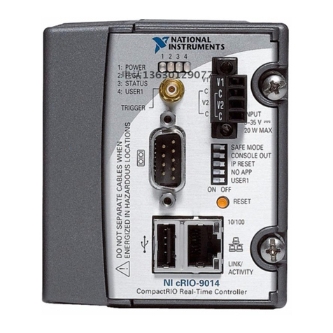
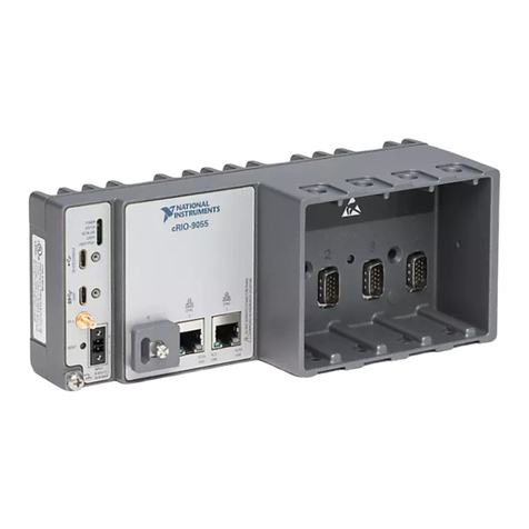
NI cRIO-904 Series User manual

GETTING STARTED GUIDE
cRIO-904x
Embedded CompactRIO Controller with Real-Time Processor and
Reconfigurable FPGA
This document describes how to begin using the cRIO-904x.
In this document, the cRIO-9040, cRIO-9041, cRIO-9042, cRIO-9043, cRIO-9045,
cRIO-9046, cRIO-9047, cRIO-9048, and cRIO-9049 are referred to collectively as cRIO-904x.
Note Refer to the device Safety, Environmental, and Regulatory Information
document, shipped with your cRIO-904x controller and available on ni.com/
manuals, for important safety and environmental specifications necessary when
setting up your device.
Unpacking the Kit
Notice To prevent electrostatic discharge (ESD) from damaging the device, ground
yourself using a grounding strap or by holding a grounded object, such as your
computer chassis.
1. Touch the antistatic package to a metal part of the computer chassis.
2. Remove the device from the package and inspect the device for loose components or any
other sign of damage.
Notice Never touch the exposed pins of connectors.
Note Do not install a device if it appears damaged in any way.
3. Unpack any other items and documentation from the kit.
Store the device in the antistatic package when the device is not in use.

What You Need to Get Started
Verify that the following items are included in the cRIO-904x controller kit.
Figure 1. cRIO-904xKit Contents
13 4
68
5
7
2
1. Controller (4-Slot or 8-Slot)
2. USB Type-A Male to USB Type-C Male Cable
3. Power Connector (Ships connected on Front
Panel)
4. Ferrite
5. SD Card Cover (Ships Connected on Front Panel)
6. Screwdriver
7. Driver Media
8. Documentation
Required Components
• Host Computer
• C Series Modules
• Power Supply
Installing Software on the Host Computer
If you do not currently have any NI software installed on your host computer, see the Install
Software section for details on required software and in which order to install it. If you have
some NI software already installed, see the Software Compatibility Resources section for
resources to check the compatibility of your software with your controller.
Install Software
Before using the cRIO-904x, you must install the following application software and device
drivers on the host computer in the order shown.
Refer to the "Choosing Your Programming Mode" section of the cRIO-904x User Manual to
determine the programming modes you wish to use.
2| ni.com | cRIO-904x Getting Started Guide

Sequence Software Corresponding Programming
Mode
1 LabVIEW 2017 SP1 or later
2 LabVIEW Real-Time Module 2017 or later
3 LabVIEW FPGA Module 2017 or later1LabVIEW FPGA Mode
4 NI CompactRIO Device Drivers 17.6 or
later2
Real-Time Mode
Real-Time Scan Mode (IO
Variables)
Note If you do not have the software media included with your hardware or do not
have a media drive, go to ni.com/downloads to download the required software.
After installing the software, you must activate it using NI License Manager.
Software Compatibility Resources
For more information about installing the correct versions of software, visit ni.com/info and
enter the Info Code swsupport.
For tips on resolving software compatibility issues with CompactRIO systems, visit ni.com/
info and enter the Info Code swcompatibility.
Note If you try to install software that already exists on your host computer, the
installer will show nothing installed.
1LabVIEW FPGA Module is not required when using Real-Time or Real-Time Scan (IO Variables)
program modes. To program the user-accessible FPGA on the cRIO-904x or deploy C Series
modules in the LabVIEW FPGA program mode, LabVIEW FPGA Module is required.
2NI CompactRIO Device Drivers 17.6 and later include NI-DAQmx driver software. To deploy
C Series modules installed in the cRIO-904x in Real-Time (NI-DAQmx) mode, ensure that NI-
DAQmx is selected during installation. To deploy C Series modules installed in the cRIO-904x in
Real-Time Scan (IO Variables) mode, ensure that NI Scan Engine is selected during installation.
cRIO-904x Getting Started Guide | © National Instruments | 3

Installing the C Series Modules
Complete the following steps to install a C Series module.
3
2
2
1
1
1. Verify that power is not connected to the I/O connector(s) on the C Series module and the
cRIO-904x.
Note If the system is in a nonhazardous location, the cRIO-904x can be
powered on when you install modules.
2. Press the latches on the C Series module.
3. Align the C Series module with a slot and seat it in the slot until the latches lock in place.
Connecting the cRIO-904x
The cRIO-904x has the following connectors, LEDs, and buttons. For a full description of all
front panel features, see the cRIO-904x User Manual.
4| ni.com | cRIO-904x Getting Started Guide

Figure 2. cRIO-904xFront Panel
13
14
123
4
5
6
7
9
11
8
10
12
1. LEDs
2. RJ-45 Gigabit Ethernet Ports
3. USER1 Button
4. PFI 0
5. RESET Button
6. Power Connector
7. Grounding Screw
8. RS-232 Serial Port
9. RS-485 Serial Port
10. USB 2.0 Type-A
11. USB 3.1 Type-C with DisplayPort Alt Mode
12. USB 3.1 Type-C Dual Role
13. SD In Use LED
14. SD Card Removable Storage
Connecting the Controller to Ground
You must connect the cRIO-904x grounding terminal to the grounding electrode system of the
facility.
What to Use
• Ring lug
• Wire, 1.3 mm2 (16 AWG) or larger
• Screwdriver, Phillips #2
What to Do
Complete the following steps to ground the cRIO-904x.
1. Attach the ring lug to the wire.
2. Remove the grounding screw from the grounding terminal on the cRIO-904x.
cRIO-904x Getting Started Guide | © National Instruments | 5

3. Attach the ring lug to the grounding terminal.
4. Tighten the grounding screw to 0.5 N · m (4.4 lb · in.) of torque.
5. Attach the other end of the wire to the chassis safety ground using a method that is
appropriate for your application.
Notice If you use shielded cabling to connect to a C Series module with a plastic
connector, you must attach the cable shield to the chassis grounding terminal using
1.3 mm2 (16 AWG) or larger wire. Attach a ring lug to the wire and attach the wire
to the chassis grounding terminal. Solder the other end of the wire to the cable
shield. Use shorter wire for better EMC performance.
For more information about ground connections, visit ni.com/info and enter the Info Code
emcground.
6| ni.com | cRIO-904x Getting Started Guide

Connecting the Controller to Power
The cRIO-904x requires a 9 V to 30 V external power supply. The cRIO-904x filters and
regulates the supplied power and provides power for the C Series modules. The cRIO-904x
has a primary power input, V1, and a secondary power input, V2.
The POWER LED on the cRIO-904x indicates which power input is in use, as shown in the
following table.
Table 1. POWER LED Indicators
LED Color LED Pattern Indication
Green Solid The cRIO-904x is powered from the V1 input.
Yellow Solid The cRIO-904x is powered from the V2 input.
— Off The cRIO-904x is off.
Notice Do not connect V1 or V2 to a DC mains supply or to any supply that
requires a connecting cable longer than 3 m (10 ft). A DC mains supply is a local
DC electricity supply network in the infrastructure of a site or building.
What to Use
• Ferrite (included in kit)
• Screwdriver, 2.54 mm (0.10 in.) flathead
• Primary power supply, 9 V to 30 V, 60 W minimum
• (Optional) Secondary power supply, 9 V to 30 V, 60 W minimum
NI recommends the power supplies listed in the following table for the cRIO-904x.
Table 2. NI Power Supplies
Power Supply Part Number
NI PS-15 Industrial Power Supply
(24 VDC, 5 A, 100 VAC to 120 VAC/200 VAC to 240 VAC input)
781093-01
NI PS-10 Desktop Power Supply
(24 VDC, 5 A, 100 VAC to 120 VAC/200 VAC to 240 VAC input)
782698-01
What to Do
Complete the following steps to connect a power supply to the cRIO-904x.
1. Ensure that your power supply is powered off.
2. Install the ferrite (National Instruments part number 711849-01, included in the shipping
kit) on the negative and positive leads of the power supply, as shown in the following
figure.
cRIO-904x Getting Started Guide | © National Instruments | 7

Figure 3. Installing a Ferrite on the Power Leads
1
2
1. Pass the leads through the ferrite twice, leaving 50 mm to 75 mm (2 in. to 3 in.) between the ferrite and
the end of the leads.
2. Close the ferrite around the leads.
3. Remove the power connector from the cRIO-904x.
Notice Do not tighten or loosen the terminal screws on the power connector
while the cRIO-904x is powered on.
Figure 4. Power Screw Terminal Connector Plug
C
V2
C
V1
2
1
2
1. Terminal Screw
2. Connector Screw Flanges
4. Connect the primary power supply and optional secondary power supply to the power
connector, as shown in the following figure.
8| ni.com | cRIO-904x Getting Started Guide

Figure 5. cRIO-904xPower Connections
Power Connector
V2
C
C
V1
Primary Power Supply
+
–
–
+
Secondary Power Supply
FerriteFerrite
Note The C terminals are internally connected to each other.
5. Tighten the terminal screws on the power connector to 0.20 N · m to 0.25 N · m
(1.8 lb · in to 2.2 lb · in) of torque.
6. Install the power connector on the front panel of the cRIO-904x.
7. Tighten the power connector screw flanges to 0.20 N · m to 0.25 N · m
(1.8 lb · in to 2.2 lb · in) of torque.
8. Power on the primary power supply and optional secondary power supply.
When you power on the cRIO-904x for the first time, the device boots into safe mode.
The POWER LED illuminates, the STATUS LED illuminates briefly, and then the
STATUS LED blinks twice every few seconds.
Connecting the Controller to the Host Computer
Complete the following steps to connect the cRIO-904x to the host computer using the Dual
Role USB C Port.
1. Power on the host computer.
2. Connect the cRIO-904x to the host computer using the USB-to-Type-A cable (included in
kit), inserting the USB Type-C connector into the Dual Role USB Type-C port. Connect
the other end of the USB cable (Type-A) to the host computer.
The device driver software automatically detects the cRIO-904x. Select Configure and
install software to this device.
cRIO-904x Getting Started Guide | © National Instruments | 9

If the device driver software does not detect the cRIO-904x, verify that you installed the
appropriate NI software in the correct order on the host computer as described in
Installing Software on the Host Computer.
Discovering the Controller in MAX
Complete the following steps to find the cRIO-904x controller in MAX.
1. Launch MAX on the host computer.
2. Expand Remote Systems in the configuration tree and locate your system.
3. Select your target.
Tip MAX lists the system under the model number followed by the serial
number, such as NI-cRIO-9048-01C0F8C4 by default.
10 | ni.com | cRIO-904x Getting Started Guide

Setting a System Password
Complete the following steps to set a system password.
1. In MAX, click the Login button on the toolbar.
2. Enter admin in the User name field.
3. Leave the Password field blank.
Note There is no default password for the cRIO-904x, so you must leave the
password field blank when logging in until you set a system password.
4. Click the OK button.
5. Click the Set Permissions button in the toolbar.
The NI Web-Based Configuration and Monitoring utility opens in your default browser
and is where you set the password. If you have not installed Microsoft Silverlight,
NI Web-based Configuration & Monitoring prompts you to do so.
6. Click the Login button and enter admin in the User name field.
7. Leave the Password field blank if you have not changed the default password, or enter
the current password.
8. Double-click admin in the list of users under the Users tab.
cRIO-904x Getting Started Guide | © National Instruments | 11

9. Click Change Password.
10. Enter and re-enter a new password.
11. Click OK.
12. Click Save.
13. Click OK to confirm you are changing the password.
Notice NI cannot recover lost system passwords. If you forget the password,
you must contact NI and reformat the controller.
14. Close the NI Web-Based Configuration and Monitoring utility.
Installing Software on the Controller
Complete the following steps to install software on the cRIO-904x.
1. In MAX, expand your system under Remote Systems.
2. Right-click Software.
3. Select Add/Remove Software to launch the LabVIEW Real-Time Software Wizard.
Tip You must log in to install software on the cRIO-904x. The default
username for the cRIO-904x is admin. There is no default password for the
cRIO-904x. To set a password for your system, refer to Setting a System
Password.
4. Select the recommended software set for your LabVIEW and NI-RIO Device Drivers
versions.
5. Click Next.
6. Select any additional software from the list of software add-ons, if needed.
Tip You can use this wizard at any time to install additional software.
12 | ni.com | cRIO-904x Getting Started Guide

Note LabVIEW FPGA Module is required to run your modules in the
LabVIEW FPGA program mode. NI Scan Engine is required to run your
modules in the Real-Time Scan (IO Variables) program mode.
7. Click Next.
8. Verify that the summary of software to install is correct.
9. Click Next to start the installation.
10. Click Finish when the installation is complete.
Testing Your Controller in MAX
Complete the following steps to run a test panel in Measurement & Automation Explorer
(MAX) to confirm that your cRIO-904x is communicating with your system.
Note MAX test panels are only available for systems running NI-DAQmx driver
software with supported C Series modules installed, and with modules deployed in
the Real-Time program mode. For additional information, refer to Installing
Software on the Host Computer and "Choosing Your Programming Mode" in the
cRIO-904x User Manual.
1. Launch MAX.
2. Locate and select your cRIO-904x system in the My System tree. If your module and the
software are functioning correctly, the System Settings for your module will show a status
of Connected - Running.
If your cRIO-904x is present but the status is Connected – Safe Mode (No
Software Installed), complete the procedure to install software on the cRIO-904x
in Installing Software on the Controller.
3. Wire the C Series module as indicated in the C Series module documentation.
4. Right-click any module and select Test Panels, or select Test Panels from the main
configuration window options.
cRIO-904x Getting Started Guide | © National Instruments | 13

5. Configure the measurement settings and click Start.
14 | ni.com | cRIO-904x Getting Started Guide

Changing Module Programming Modes in MAX
Complete the following steps to deploy your C Series module in a new program mode in
MAX.
1. Launch MAX on the host computer.
2. Expand Remote Systems in the configuration tree and locate your cRIO-904x system.
3. Select the C Series module you wish to program.
4. In the Settings pane, choose the Program Mode you wish to deploy the module in from
the drop-down menu.
cRIO-904x Getting Started Guide | © National Instruments | 15

5. Click Save.
The module is deployed in the program mode. Notice the module icon changes to
represent the program mode.
1
2
3
1. Real-Time Mode
2. Real-Time Scan (IO Variables) Mode
3. LabVIEW FPGA Mode
16 | ni.com | cRIO-904x Getting Started Guide

Troubleshooting the Controller
The cRIO-904xis Not Communicating with the
Network
• Ensure that the USB connections between the cRIO-904x and the host computer and the
Ethernet connections between the host computer and the router are secure.
• Configure the IP and other network settings by completing the following steps.
1. Use a USB-to-Type-A cable (included in the kit) to connect the cRIO-904x USB
device port to a host computer. The USB driver creates a virtual network interface
card and assigns an IP address to the cRIO-904x in the format of 172.22.11.x.
2. In MAX, expand your system under Remote Systems.
Tip If you do not see the cRIO-904x under Remote Systems, use the
Troubleshoot Remote System Discovery utility to walk through
troubleshooting steps.
3. Select the Network Settings tab to configure the IP and other network settings.
4. (Optional) Use the RJ-45 Ethernet port 0 to reconnect the cRIO-904x to the host
computer. The cRIO-904x attempts to initiate a DHCP network connection at
powerup.
Note If the cRIO-904x cannot obtain an IP address, it connects to the
network with a link-local IP address with the form 169.254.x.x. The host
computer communicates with the cRIO-904x over a standard Ethernet
connection.
• Ensure that you have the correct version of NI CompactRIO Device Drivers installed on
the host computer. Visit ni.com/info and enter the Info Code swsupport for the
minimum supported versions of LabVIEW and NI CompactRIO Device Drivers.
Tip If you have recently upgraded LabVIEW, you must reinstall NI
CompactRIO Device Drivers.
• Ensure that the NI USBLAN adapter is recognized in the Device Manager. On
Windows 7, select Start»Control Panel»Device Manager»Network adapters»National
Instruments»USBLAN adapter. If the USBLAN adapter is not recognized, you must
reinstall NI CompactRIO Device Drivers.
• Temporarily disable any network firewalls or other security software.
Verify the System IP Configuration
1. Put the cRIO-904x in safe mode and enable the RS-232 serial port by holding the RESET
button down for 5 seconds.
The STATUS LED starts blinking three times every few seconds.
cRIO-904x Getting Started Guide | © National Instruments | 17

2. Use the RS-232 serial port terminal to read the IP address, or connect a monitor to the
mini DisplayPort to view the IP address.
Note Refer to the cRIO-904x User Manual for more information about serial
port configuration.
3. Set a new DHCP connection by holding the RESET button down for 5 seconds. The
STATUS LED repeats the same behavior from Step 1.
If the cRIO-904x fails to set a new DHCP address, it assigns itself a link-local IP address.
If the DHCP connection is successful and appropriate for your application, skip to Step 6.
4. In MAX, expand your system under Remote Systems.
5. Select the Network Settings tab to configure the IP and other network settings.
6. Reboot the cRIO-904x by pressing the RESET button.
Configure the Windows Firewall
• Add an exception for MAX to your network firewall or other security software by
completing the following steps:
1. On Windows 7, select Start»Control Panel»System and Security»Windows
Firewall»Allow a program through Windows Firewall.
2. Click Allow another program.
3. Select Measurement & Automation.
4. Click Add.
5. Click OK.
• Ensure that UDP port 44525 is open to communication on the host computer. If you are
using an intelligent switch on the network, ensure that it is not disabling UDP port 44525.
System Reset
The following figure shows the reset behavior of the cRIO-904x.
Figure 6. Reset Button Behavior
Press and hold RESET button for ≥5 s
Press and hold RESET button for < 5 s
Run Mode
Safe Mode
Press and hold RESET button for < 5 s
Press and hold RESET button for ≥5 s
Press and hold
RESET button for ≥5 s
Press and hold
RESET button for < 5 s
• Console Out enabled
• Network settings reset
• RT Startup App disabled
• FPGA Startup App disabled
• Console Out enabled
• RT Startup App disabled
• FPGA Startup App disabled
Safe Mode
18 | ni.com | cRIO-904x Getting Started Guide

STATUS LED Indicators
The following table describes the STATUS LED indicators.
Table 3. STATUS LED Indicators
LED
Color
LED Pattern Indication
Yellow Blinks twice and
pauses
The cRIO-904x is in safe mode. Software is not installed,
which is the factory default state, or software has been
improperly installed on the cRIO-904x.
An error can occur when an attempt to upgrade the software
is interrupted. Reinstall software on the cRIO-904x. Refer to
Installing Software on the Controller for information about
installing software on the cRIO-904x.
Blinks three times
and pauses
The cRIO-904x is in user-directed safe mode, or the
cRIO-904x is in install mode to indicate that software is
currently being installed.
This pattern may also indicate that the user has forced the
cRIO-904x to boot into safe mode by pressing the reset
button for longer than five seconds or by enabling safe mode
in MAX. Refer to the Measurement & Automation Explorer
(MAX) Help for information about safe mode.
Blinks four times
and pauses
The cRIO-904x is in safe mode. The software has crashed
twice without rebooting or cycling power between crashes.
Continuously
blinks
The cRIO-904x has not booted into NI Linux Real-Time.
The cRIO-904x either booted into an unsupported operating
system, was interrupted during the boot process, or detected
an unrecoverable software error.
On momentarily The cRIO-904x is booting. No action required.
cRIO-904x Getting Started Guide | © National Instruments | 19

Table 3. STATUS LED Indicators (Continued)
LED
Color
LED Pattern Indication
Red Continuously
blinks
This indicates a hardware error. An internal power supply
has failed. Check front-panel I/O and C Series module
connections for shorts. Remove any shorts and cycle power
the cRIO-904x. If the problem persists, contact NI.
Solid The cRIO-904x internal temperature has exceeded a critical
threshold. Ensure the ambient operating temperature does
not exceed the specified operating temperature. If the
problem persists, contact NI.
— Off The cRIO-904x is in run mode. Software is installed and the
operating system is running.
Using the cRIO-904xin LabVIEW
Visit the following topics for information on how to create a new LabVIEW Project
configured with the cRIO-904x, and how to deploy the C Series module in the Real-Time,
Real-Time Scan (IO Variables), or LabVIEW FPGA program modes.
Using the
cRIO-904x in
LabVIEW
Programming Modes:
• Real-Time
• Real-Time Scan (IO
Variables)
1. Adding the cRIO-904x to a
LabVIEW Project
2. Deploying Your C Series Module
in a Program Mode in LabVIEW
Using the
cRIO-904x in
LabVIEW FPGA
(Requires LabVIEW
FPGA Module)
Programming Modes:
• Real-Time
• Real-Time Scan (IO
Variables)
• LabVIEW FPGA
1. Adding the cRIO-904x to a
LabVIEW FPGA Project
2. Deploying Your C Series Module
in a Program Mode in LabVIEW
FPGA
Adding the cRIO-904xto a LabVIEW Project
Complete the following steps to create a new LabVIEW project configured with the
cRIO-904x controller.
You can use LabVIEW to program in Real-Time (NI-DAQmx) or Real-Time Scan (IO
Variables) modes. For applications using advanced functionality that require programming the
FPGA, LabVIEW FPGA Module is required to deploy C Series modules in the LabVIEW
20 | ni.com | cRIO-904x Getting Started Guide
This manual suits for next models
9
Table of contents
Other NI Controllers manuals
Popular Controllers manuals by other brands

Danfoss
Danfoss VLT AutomationDrive FC 300 Design guide

Jung
Jung Smart Control 7 Product documentation

hager
hager TX206H User instructions

Josef Barthelme
Josef Barthelme 66000341 instruction manual

MDT Technologies
MDT Technologies BE-GT2TW.01 operating instructions

Eaton
Eaton easyControl EC4-200 user manual