Toky T52L Series User manual

Temperature Acquisition Module
User Manual
(T52L Series)
(For T52L A Version)
广东东崎电气有限公司
TOKY electrical co.,ltd. http://www.toky.com.cn
⊙PT100 input, temperature unit Fahrenheit or Celsius can be selected
⊙With many functions, measured display, disconnection detection, RS485 communication, etc
⊙Communication address can be set by toggle switch
⊙This product is used in lithium battery high vacuum baking equipment
2
T52L-PF-12P8 A
P: No shell board
T52L: Temperature acquisition module
F: DC 24V power supply
12: 12 channel 08: 8 channel
P: PT100 input
RS485
communication
port
Power
: Functional insulation DC 500V
PT100 CH1-CH12 input
66.0mm
91.0mm
10.0mm
4.0mm
24V+
POWER ADD RUN 4*φ4
COMM
PT100 INPUT 1-12
GND
B-
A+
99.0mm
48.0mm
ISO9001
国家高新技 术企业
1
National High-tech Enterprise/ National Standard Drafting Unit
Version code:KKT52L-A01E-A/0-20221202
Hotline:400-0760-168
Caution
1)When the failure or abnormality of this product may lead to serious system accidents, please
set proper protection circuits in the external.
2)The product may occur radio interference when it used at home.You should take adequate
countermeasures.
3)The product get an electric shock protection through reinforced Insulation. When the product
is embedded in the devices and wiring,please subject to the specification of embedded
devices.
4)In order to prevent surge occurs,when using this product in the place of over 30m indoor
wiring and wiring in outdoor, you need to set the proper surge suppression circuitry.
5)The product is produced based on mounting on the disk.In order to avoid to touch the wire
connectors,please take the necessary measures on the product.
6)Be sure to observe the precautions in this manual, otherwise there is a risk of a major injury
or accident.
7)When wiring, please observe the local regulation.
8)To prevent to damage the machine and prevent to machine failure, the product is connected
with power lines or large capacity input and output lines and other methods please install
proper capacity fuse or other methods of protection circuit.
9)Please don't put metal and wire clastic mixed with this product,otherwise it may lead to
electric shock, fire, fault.
10)Please tighten screw torque according to the rules.If not,it may lead to electric shock and
fire.
11)In order not to interfere with this products to dissipate heat, please don't plug casing around
the cooling vent hole and equipment.
12)Please don’ t connect any unused terminal.
13)Please do the cleaning after power off, and use the dry cleaning cloth to wipe away the dirt.
Please don’ t use desiccant, otherwise, it may casue the deformation or discoloration of the
product.
14)Please don`t knock or rub the panel with rigid thing.
15)The readers of this manual should have basic knowledge of electrical,control, computer and
communications.
16)The illustrations, data examples and picture examples used in this manual are recorded for
the convenience of understanding the manual, and are not guaranteed to be the results of
the operation.
17)In order to use this product with safety for long-term,regular maintenance is necessary. The
life of some parts of the equipments are by some restrictions, but the performance of some
will change for using many years.
18)Without prior notice, the contents of this manual may will be change. We hope these is no
any loopholes, if you have questions or objections, please contact us.
19) Our company will not liable for any indirect losses suffered by users or third parties, such
as the results impact of using this product, unpredictable product defects, imitations of this
product and other indirect losses.
I. Safe Caution
The instruction explain T52L series instrument settings, connections,name and etc, please
read carefully before you use the temperature controller. Please keep it properly for necessary
reference.
1) Please don`t plug in before completing all the wire.Otherwise it may lead to electric shock,
fire, fault.
2) Don’ t touch power terminal and other high voltage part when the power on, otherwise you
may get an electric-shock.
3)Don’ t remove,repair and modify this product,otherwise it may lead to electric shock, fire,
fault and electrical Danger.
1) Not allow to use outside the scope of product specification,otherwise it may lead to fire,fault.
2) Not allow to use in the place where is inflammable and explosive gas.
3) The product should not be used in a nuclear facility and human life associated medical
equipment.
Warning:
Electric-shock
Warning:
Forbiddance
1. Installation
1) This product is used in the following environmental standards.
(IEC61010-1)[Overvoltage categoryⅡ、class of pollution 2]
2)This product is used in the following environment:Temperature range:-20 ~125℃;humidity:
45~85%RH; environment condition:Indoor use. The altitude is less than 5000m.
Caution of Installation & Wiring
Features:
3) Please avoid using in the following places:
The place will be dew for changing temperature;with corrosive gases and flammable
gas; with vibration and impact;with water, oil, chemicals, smoke and steam facilities with
dust, salt, metal powder;and with clutter interference, static electric and magnetic fields,
noise;where the air from air conditioning or heating is blowing directly; where will be
illuminated directly by sunlight; where accumulation of heat will happen caused by radiation.
4) On the occasion of the installation, please consider the following before installation.
In order to prevent heat saturated, please open enough ventilation space.
Please consider connections and maintenance environment,and ensure that there is more
than 50mm space above and below the product.
Please avoid to install the product above the machines with high the calorific value (Such as
heaters, transformer, semiconductor operations, the bulk resistance).
The surrounding environment shall not exceed the limit of using conditions.
In order to improve the anti - interference performance and security, please try to stay away
from high pressure machines, power machines to install.
Don`t install on the same plate with high pressure machine and the product.
The distance should be more than 200mm between the product and power line.
The power machine shall be installed at a distance as far as possible.
2. Cable caution:
1)Please use specified compensation wire in the place of TC input; Please use insulated TC
if the measured device is heated metal.The influence of external resistance is about 0.3 μ
V/Ω。
2)Please use the cable with small wire resistance in the place of RTD input,and the cable
(3 wire) must be no resistance difference, The wire should be run in parallel and the cable
length should less than 5m.
3)In order to avoid the effect of noise,please wire the input signal away from meter
cable,power cable,load cable.
4)In order to reduce the power cables and the load power cables on the effect of this product,
please use noise filter in the place where easy to effect. You must install it on the grounding
of the disk if you use the noise filter,and make the wiring to be shortest between noise filter
output side and power connectors. Don`t install fuse and switch on the wiring of noice filter
output side,otherwise it will reduce the effect of noise filter.
5)It takes 5s from input power to output.If there is a place with interlocking actions circuit
signal,please use timer relay.
6)Please use twisted pair with a shield for analog output line, can also connect the
common-mode coil to the front-end of the signal receiving device to suppress line
interference if necessary, to ensure the reliabilty of signal.
7) Please use twisted pair with a shield for remote RS485 communication cable, and deal with
the shield on the host side earth, to ensure the reliabilty of signal.
8)This product don’ t have the fuse; please set according to rated voltage 250V, rated current
1A if you need; fuse type:delay fuse.
9)Please use suitable screw force and suitable crimping terminal
Terminal screw size: see real object
Recommended terminal tightening torque: 0.4N.m.
Proper cables: 0.25 ~1.65mm single cable/multiple core cable
10)Please don’ t put the Crimp terminal or bare wire part contact with adjacent connector.
II. Model Illustration A: Version
8: With RS485 communication
III. Specifications
1. Electrical parameters:
Sampling rate 2 times per second
Power supply
Power consumption 10 ~30V DC
< 1VA
Communication port RS485 port Modbus-RTU protocol
Voltage drop & short
interruption immunity
Isolation voltage
Pulse traip
anti-interference
ESD IEC/EN61000-4-2 Contact ±4KV /Air ±8KV perf.Criteria B
IEC/EN61000-4-4 ±2KV perf.Criteria B
IEC/EN61000-4-29 0% ~70% perf.Criteria B
Signal input and commnucation port DC500V,1min
Power failure memory 5 years, times of writing: 1 million times
2. Non-electrical parameters:
Ambient
conditions Indoor use only, temperature: -20-125℃no condensation,
humidity<85%RH, altitude<5000m
Total weight About 150g
Shell and panel base frame PC / ABS (flame retardant UL94V-0)Shell material
-40 ~140℃,no condensation
Storage
environment
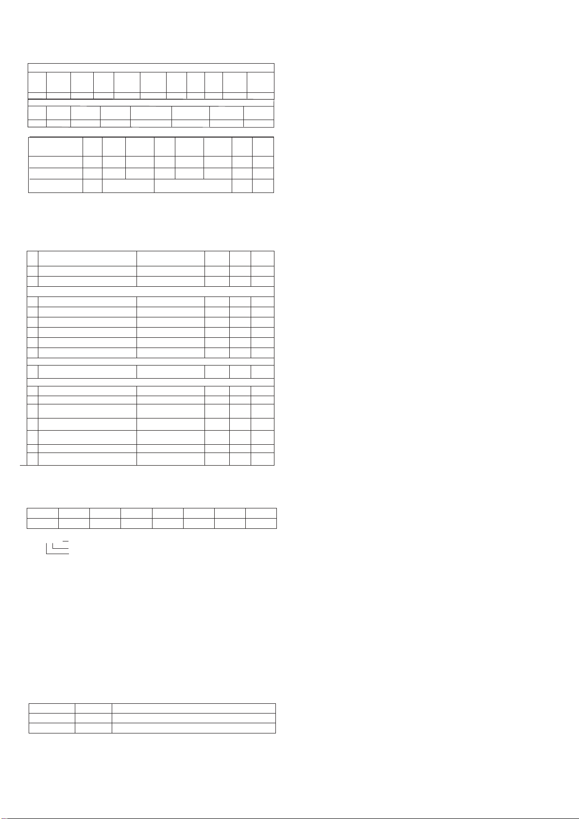
3、Measured signal specifications :
PT1
PT2
0~150.0
0~150
0.1℃
1℃
0.5%F.S±0.3℃
0.5%F.S±3digits 0
1
Input type Measuring range Resolution Accuracy
Communication
code
4. Isolation diagram:
IV. Dimension and Installation Method

3 4
VI.Networking application
1
013
14
15
RCVF 0~9999
--
--
ADD Communication
address (can be set
by toggle switch) 1~4 1
5
6
7
8
10
11
9
INP
PV Measured value
Input signal type selection: see the corresponding
table of measuring signal parameters for details
--
0~1
PS Amend value, display value= actual measured value
+ amend value -1000~1000 0
0
FL 0
FH 1500
FT 0~255 10
UNIT ℃/℉25(℃)
12 PRS 0~10
2
DTC
See
communication
protocol
4
BAD RS485 Baud rate 0:4800;1:9600 2:19200 3:38400
4:57600 5:115200 0~5 3
PRTY Parity bit setting, 0:NONE, 1:ODD parity,
2:EVEN parity 0~2
0
03
Communication data transmission sequence setting;
When it is set to 10, data bytes are exchanged
sequentially, and the default value is 0.
Write 123 can restore factory settings
RTC Ambient temperature, 1 decimal place --
VER
16 Total channels quantity , query total quantity of
channels in different application schemes
LOOPSUM --
1 2 3 4
1:1 control is applied for 1 patrol inspection,
acquisition 1 is connected to controller,
acquisition 2 is connected to PLC (patrol inspection)
One collection
board + controller
combination to
realize temperature
acquisition and control A acquisition board communicates
with PLC to realize temperature acquisition
RS485 RS485
(Need to be purchased separately)
Note: 1. Different network application schemes can be customized through communication
with our company technician
2. This manual only introduces the application of the acquisition board.
The products used in the scheme other than the acquisition board need to be equipped
separately,Our company provides PID controller and Modbus communication gateway.
Please contact our relevant personnel for details.
(PLC/HMI is not
equipped )
Acquisition board 1
PLC/HMI/Gateway
Two acquisition boards
communicate with the
controller to realize
temperature acquisition
and heating control
Application 2: The acquisition board is connected with the temperature controller.
No. Name Description Remark
01
02
03
04
01-A/B/C/D: fixed screw holes of four acquisition boards( φ= 4)
Power supply:10~30VDC (+24V=positive, GND=negative)
Communication: A+/B - connect the upper computer PLC or our
temperature controller
Select different communication addresses of the acquisition board
0x01 ~0x04
02: Single/double connecting terminal,used for connecting with
PT100 temperature sensor.Note: PT100 sensor is a 3-wire sensor
Sensor channel
Fixed screw hole
Power input interface
RS485 interface
05 used for device firmware upgradeInterface upgrade
485 address selection
A
B
C
D
Positive input terminal of power supply
RS485 "-" terminal, connected to PLC or our temperature controller
Negative input terminal of power supply
RS485 "+" terminal, connected to PLC or our temperature controller
GND
+24V
A+
B-
channel 1
channel 2
B1B1A1B3B3A3
B2B2A2B4B4A4
24V+
GND
B-
A+
A
B
C
D
24V+
01-A
03
01-B
01-C
04 05
02
01-D
POWER ADD RUN
COMM
PT100 INPUT 1-12
GND
B-
A+
V.Interface function introduction
2. Wiring description for power supply and RS485
1. Interface description of temperature acquisition module
3. Sensor wiring description
RS485 -RS485
No. Name Description
VIII . Methods of simple fault
Display info
LLLL/HHHH
Method
Check the input whether is disconnected; check the FH value and FL value;
check the working environment temperature whether is normal; check the
input signal selection whether is correct.
Meter adopts RS485 Modbus RTU communication protocol, Read function code 0x03 of the
holding register in zone 04, write function code 0x10/0x06. Adopt 16 digit CRC check, the
meter does not return for error check. The data type is a 16 bit signed or unsigned integer.
Data frame format:
Start bit
Data bit
1 8 1 None/odd parity/even parity
Stop bit Check bit
IX. Communication procotol
1. Read register
For example:Host reads SV(PV1 = 200)
The address code of SV is 0x2000 ("0x" represents for hexadecimal), because SV data type
is a 16-bit integer (2 bytes),seizes 1 data register. The memory code of decimal integer 200
convert to hexadecimal code is 0x00C8.. Note: When reading data, should determine the
decimal point position firstly and then convert the reading data to obtain the actual value.
CRC
Code CRC
Code
0x01
0x01
0x01 0x03
0x83
0x03 0x02
0x20
0x02
0x00
0x00 0xC8 0xC0
0xB9 0xD2
0xCA0x8F0x01
0xF1
0x00
error code
bits
For example:Host request address is 0x2011
Read multi-register
Host request
Slave normal answer
Slave abnormal answer
Meter
ADD
Function
code
Start
ADD
High bit
Start
ADD
Low bit
Data byte
Length
high bit
Data byte
Length
low bit
Acquisition board 2
(Need to be purchased separately)
VII. Menu Illustration
1. Regular Menu
No.
Name
Illustration Setting
range Factory
setting
Measure range low limit, the set value must be less
than measure range high limit
Measure range high limit,the setting value must be
more than measure range low limit.
Filter coefficient, the higher of value, the stronger
of filter function
Temperature unit setting:25: Celsius degrees ℃.
26:Fahrenheit degrees ℉
Software version
Setting parameter saving address:
0 (EEP): EEPROM has power failure protection;
1 (RAM): RAM no power failure protection
Refer to
measured signal
parameter table
Refer to
measured signal
parameter table
5 6
unsigned int Get_CRC(uchar *pBuf, uchar num)
{
unsigned i,j;
unsigned int wCrc = 0xFFFF;
for(i=0; i<num; i++)
{
wCrc ^= (unsigned int)(pBuf[i]);
for(j=0; j<8; j++)
{
if(wCrc & 1){wCrc >>= 1; wCrc ^= 0xA001; }
else
wCrc >>= 1;
}
}
return wCrc;
}
X. Version and Revision History
2022.12.02
NO
1
2R
1
Status value R1②
0x200C~0x2017(48205~48216)
0x2000~0x200B(48193~48204)
3
4
5
6
7
8
R/W
1
R/W1
1R/W
R/W
1R/W1
R/W1
0x210C~0x2117(48461~48472)
0x2100~0x210B(48449~48460)
0x2124~0x212F(48485~48496)
0x2118~0x2123(48473~48484)
0x213C~0x2147(48509~48520)
0x2130~0x213B(48497~48508)
9 R/W10x2400~0x240B(49217~49228)
③
12
10
11
13
14
15
16
R/W1
R/W1R/W1
R/W1
R1
R1
Restore factory settings
RCVF
Total channels quantity
Software version VER
R1
Ambient temperature of
acquisition board RTC
0x2503(49476)
0x2502(49475)
0x2501(49474)
0x2500(49473)
0x2505(49478)
0x2504(49477)
0x2506(49479)
Host write SV with 06 function(SV= 150)
0x01 0x10 0x21 0x10 0x00 0x01 0x02 0x00 0x96
Meter
ADD Function
code Start ADD
High bit Start ADD
Low bit Data byte
length high bit Data byte
length low bit ※CRC code
low bit
※CRC code
high bit
Slave normal answer (write multi-register)
0x300x0A0x010x000x100x210x100x01
Meter
ADD Function
code Start
ADD
High bit
Start
ADD
Low bit
Data byte
Length
high bit
Data
high
bit
Data
low
bit
Data byte
Length
low bit
Data
byte
Length
Host request (write multi-register)
0x15 0xAC
CRC
code CRC
code
0x00
0x10
0x21
0x060x01
0x5d0x020x96
0x5d
0x020x96
0x000x100x210x060x01
0xA10x01 0x86 Error Code0x02 0xC3
Write single
register Meter
ADD
Function
code
Start
ADD
Low bit
Start
ADD
High bit
CRC
Code CRC
Code
Data byte
Length
low bit
Data byte
Length
high bit
Host request
Slave normal answer
Slave abnormal
answer
Function
code
Handling of abnormal communication:
When abnormal response,put 1 on the highest bit of function code. For example: Host request
function code 0x03,and slave response function code should be 0x83.
Error code:
0x01---Illegal function: the function code sent from host is not supported by meter.
0x02---Illegal address:the register address designated by host beyond the address range of meter.
0x03---Illegal data: Date value sent from host exceeds the corresponding data range of meter.
2. Write multi-register
For example:Host use 10 function code write SV(SV=150)
ADD code of SV1 is 0x2110,because
SV1 data type is a 16-bit integer (2 bytes),seizes 1 data
register.
The decimal integer 150 convert to hexadecimal code is 0x0096. Before writing the data,
you should convert the data to the corresponding magnification and then writing the data into the
instrument.
Meter parameters address mapping table
Address (Register No①) Register R/W RemarkVariable name
Measured value PV
Reserve
Input signal selection INP
Display low limit FL
Display high limit FH
Amend value PS
Filter constants FT
Measuring Unit UNIT
Reserve
Reserve
Paramters saving
address PRS
baud rate BAD
Parity Check PRTY
Communication data
transfer sequence DATC
1st edition
A/0 Version
Date Version Revision content
---- HHHH LLLL
℃
℉----
D7 D6 D5 D4 D3 D1 D0
----
D2 ----
Note①: The register number is the address converted to decimal plus 1 and then the register
identification code 4 is added in front; for example: the register number of the data address
0x2000 is 8192 + 1 = 8193 and then 4 is added in front, that is, the register number 48193;
Related applications can be seen, such as Siemens S7-200 PLC.
Note ②: Measurement status indication. When the data bit is 1, it means execution, and when it
is 0, it means no execution.
□ □ □
DATC:
Note③: DATC communication data transmission sequence description
Reserve
Byte transfer order: when it is 0, 1, 2, and when it is 1, 2, 1
Reserve
Manufacturer contact information:Toky Electrical Co., Ltd
Add: No.8 Minke West Rd, Shiqi District, Zhongshan, Guangdong, CN 528400
Contact:0760-23371800
Technical consultation contact:400-0760-168
Web:http://www.toky.com.cn
※16-bit CRC check code to get C program
Popular Control Unit manuals by other brands

MAZATROL
MAZATROL M PLUS Series Maintenance manual

CAME
CAME PXC2-32 Installer manual

Siemens
Siemens Flowrite 599 Series Technical instructions

Kohler
Kohler K-10668 Homeowner's guide

Redi Controls
Redi Controls RuptureSeal RS-2 operation & maintenance

extronics
extronics ISOLATE 100: ISOLATE 100M operating manual


EOS
EOS Compact D18 Installation and operating instructions

SEA
SEA SWING 2 manual

Honeywell
Honeywell D06FN-1B Installation instruction

Beehive International
Beehive International DM3270 Technical user's manual

CAMBRIONIX
CAMBRIONIX ModIT-Boss user manual

Burkert
Burkert AirLINE 8652 Series operating instructions