Tomar TRX-20 User manual
IS0615-02
12/15/2016
TOMAR OFF-ROAD, 2100 W OBISPO AVE, GILBERT, AZ 85233
800-338-2133 www.tomaroff-road.com
Product Manual
TRX SERIES LIGHTBARS
TRX-20 TRX-25 TRX-30 TRX-35
TRX-40 TRX-45 TRX-50 TRX-60

IS0615-02
Page 2of 9
Wiring
Main Power Wires
Wiring the TRX lightbar into the vehicles electrical system does not require the use of relays. The power
and ground leads are connected directly to the 12Vdc to 24Vdc supply voltage and are always hot.
Red to +Vdc
Black to -Vdc
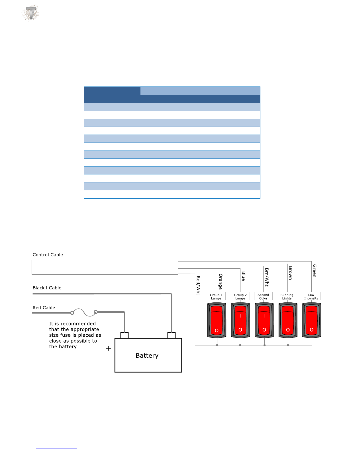
Control Cable
Activating the Lightbar is done by applying +Vdc to one or more of the lightbar control wires. The control
wires consume only a few milliamps of current and can be used with virtually any on/off switch. There
are five control wires in the Control Cable plus one +Vdc supply feed.
The control wires are color coded and control the functions shown below. Keep in mind that not all
lightbars will be configured in such a way that all control wires are used.
Orange - Group 1 lamps
Blue - Group 2 lamps or Second Color lamps
Brown/White - S.O.S. warning pattern
Brown wire - Running lamps
Green wire - Dimming of all lamps
Red/White - +Vdc
Orange Wire –On single color single beam pattern bars the orange wire will turn on the entire bar. If
the lamps in the lightbar are two beam patterns, half spot and half flood for example, the orange wire
will turn on just the spot lamps.
Blue Wire –If all the lamps in the lightbar have the same beam pattern the blue wire will have no have
no effect on the lightbar and can be ignored. If the lamps in the lightbar are two different beam
patterns, some spot and some flood for example, the blue wire will turn on just the flood lamps. If you
have a multi-beam pattern lightbar and just want on/off functionality simply wire both the orange and
blue wires to a single switch.
If the lightbar is configured as an amber/white combination bar the orange wire will activate the white
lights and the blue wire will activate the amber lights. In case both the orange and blue wires are
activated at the same time the amber lights will activate and the white lights will shut off.
Brown Wire - If the lightbar is configured as an amber/white combination bar, and the amber lights are
activated, the Brown wire will force one lamp to remain white to serve as the required front facing
white light.
Brown/White Wire –Activates the S.O.S. or warning patterns. See below for available flash patterns.
Green Wire –In all lightbars the green wire activates a low intensity or dim setting.
Red/White Wire –In all lightbars the red/white wire is a +Vdc feed that can be used to power one or
more switches.

IS0615-02
Page 3of 9
Amber/White Combo Available Flash Patterns and Rates:
Patterns
1) Off
2) Amber Combination (Patterns 5,4,6 Repeat) Default Pattern
3) White S.O.S.
4) Amber Alternating
5) Amber Random
6) Amber Sweep
Rates
1) Single –Default Rate
2) Double
3) Neobe
4) Scroll
Note: The White S.O.S. Flash Pattern has a fixed Flash Rate (5 WPM, not listed above).
Changing Patterns and Rates:
To Enter Programming Mode:
1) All Inputs Open, apply Power and ground to the lightbar.
2) Green wire connected to +V.
3) Wait at least one second, Double Tap the Brown wire to +V. All the lamps should flash 3 times to
indicate you've entered Programming Mode.
Note: The Double Tap of the Brown wire must occur within 4 seconds of connecting the Green wire to
+V, otherwise the lightbar will NOT enter Program Mode and will operate normally.
To change the Flash Pattern:
1) Brown/White wire must be Open, i.e. not connected to +V.
2) Tap the Brown wire to +V to step forward through the patterns.
3) Tap the Brown wire to +V twice to step backward through the patterns.
4) Tap and Hold the Brown wire to +V for 3 seconds to reset the pattern to the default flash pattern.
To change the Flash Rate:
1) Connect the Brown/White wire to +V.
2) Tap the Brown wire to +V to step forward through the flash rates.
3) Tap the Brown wire to +V twice to step backward through the flash rates.
4) Tap and Hold the Brown wire to +V for 3 seconds to reset the pattern to the default flash rate.
IS0615-02
Page 4of 9
Wire Runs
The table below lists the maximum recommended wire run for the power and ground cables in feet. The
control cable can be the same length as the power cables but 20 gauge wire is sufficient for all distances.
Part
Number
Lamps
WIRE GAUGE
18
16
14
12
10
8
TRX-03
1
89
142
225
361
575
914
TRX-06
1
51
81
129
206
328
522
TRX-10
2
25
40
64
103
164
261
TRX-15
3
27
42
68
108
174
TRX-20
4
20
31
50
82
130
TRX-25
5
16
25
41
65
104
TRX-30
6
21
34
54
86
TRX-35
7
18
29
46
74
TRX-40
8
25
41
65
TRX-45
9
22
36
57
TRX-50
10
32
52
TRX-60
12
27
43
Common Switch Wiring Configuration

IS0615-02
Page 5of 9
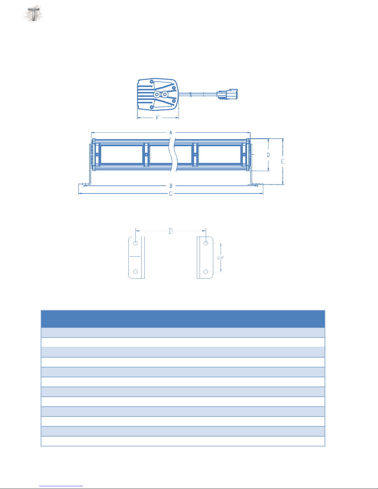
Mounting
TRX lightbars include L shape mounting brackets designed to secure the lightbar to a flat surface. The
bracket will allow a 135° range of motion. For additional mounting options visit www.tomaroff-
road.com.
1. Attach the mounting foot to the lightbar using the 1/4 -20 socket head screws and ¼” flat
washers included with the lightbar, leaving the screws finger tight.
2. Place the lightbar with attached mounting feet on a flat surface that has sufficient
strength to support its weight. Using the holes in the mounting brackets as a template
mark the location of the mounting holes. The mounting holes in the bracket are designed
to free fit ¼ inch hardware. Recommended drill sizes for ¼” hardware are 17/64” for
clearance holes and 13/64 for tapped holes. Note: the hole pattern on the foot is on 2”
centers. For the hole spacing between the mounting feet refer to the Dimensions section
below.
3. Once the lightbar is secured to the mounting surface, adjust the lightbar to the desired
angle and tighten the ¼-20 socket head screws to approx. 36 in/lb.
IS0615-02
Page 6of 9
Dimensions
Nominal
Length
Lamps
Dim "A"
Dim "B"
Dim "C"
Dim "D"
Dim "E"
Dim "F"
3
1
3.41
4.66
5.66
3.00
4.25
3.82
6
1
5.68
6.93
7.93
3.00
4.25
3.82
10
2
10.23
11.48
12.48
3.00
4.25
3.82
15
3
14.78
16.03
17.03
3.00
4.25
3.82
20
4
19.33
20.58
21.58
3.00
4.25
3.82
25
5
23.88
25.13
26.13
3.00
4.25
3.82
30
6
28.43
29.68
30.68
3.00
4.25
3.82
35
7
32.98
34.23
35.23
3.00
4.25
3.82
40
8
37.53
38.78
39.78
3.00
4.25
3.82
45
9
42.08
43.33
44.33
3.00
4.25
3.82
50
10
46.63
47.88
48.88
3.00
4.25
3.82
60
12
55.73
56.98
57.98
3.00
4.25
3.82
Mounting Hole Spacing
Outside Dimensions

IS0615-02
Page 7of 9
Recommended Fuse/Breaker Sizing
Replacing a lamp module
All TRX lamp modules are interchangeable and can be used in any position on the lightbar. This offers
the flexibility to configure a lightbar for any mission with perfect balance of flood, spot or dual color
amber white modules.
With this modular design the replacement of a TRX Lamp couldn’t be easier. Each module is hermetically
sealed so replacement will not compromise the watertight integrity of the lightbar or void the warranty.
To replace a lamp module simply remove the two lamp clips using a 9/64”hex tool. Unplug the lamp
from the waterproof connector, plug the new lamp in and reattach the lamp clips.
Part
Number
Lamps
Amp draw
@13.8Vdc
Fuse/Breaker
Size (A)
TRX-03
1
1.3
3
TRX-06
1
2.1
5
TRX-10
2
4.2
10
TRX-15
3
6.3
12
TRX-20
4
8.4
15
TRX-25
5
10.5
20
TRX-30
6
12.6
25
TRX-35
7
14.7
30
TRX-40
8
16.8
35
TRX-45
9
18.9
40
TRX-50
10
21.0
45
TRX-60
12
25.2
50

IS0615-02
Page 8of 9
Maintenance
The best cleaning method is to gently wash the lightbar with a solution of mild soap and
lukewarm water, using a soft cloth or sponge to loosen any dirt or grime. Thoroughly rinse with
clean water to remove any cleaner residue and dry the surface with a soft cloth to prevent water
spotting.
If using a high-pressure water cleaner and/or a steam cleaner the pressure should not exceed
1,450psi. The use of additives to the water and/or steam should also be avoided.
Important Considerations for Lexan lenses:
• Never use abrasive or highly alkaline cleaners.
• Never use aromatic or halogenated solvents like toluene, benzene, gasoline, acetone or carbon
tetrachloride.
• Contact with harsh solvents such as methyl ethyl ketone (MEK) or hydrochloric acid can result
in surface degradation and possible crazing.
• Never scrub lenses with brushes, steel wool or other abrasive materials.

IS0615-02
Page 9of 9
Addendum: TRX-35x-STTRAB Model Control Wiring
Wiring
Control Cable
Activating the Lightbar is done by applying +Vdc to one or more of the lightbar control wires. The control
wires consume only a few milliamps of current and can be used with virtually any on/off switch. There
are five control wires in the Control Cable plus one +Vdc supply feed.
The control wires are color coded and control the functions shown below.
Orange - Red and Amber lamps (Group 1 lamps)
Blue - Blue lamp (Group 2 lamp)
Brown/White - Left STT Stop/Turn function
Brown wire - Right STT Stop/Turn function
Green wire - Left & Right STT Tail function
Red/White - +Vdc
Orange Wire –Turns on the Red and Amber lamps.
Blue Wire –Turns on the Blue lamp.
Brown Wire - Turns on the Right STT lamp's Stop/Turn function.
Brown/White Wire –Turns on the Left STT lamp's Stop/Turn function.
Green Wire –Turns on the Tail function of both the Right and Left STT lamps.
If while the Green wire is activated, the Brown Wire or Brown/White wire is also activated, the Right or
Left, respectively, Stop/Turn function will override the Tail function.
Red/White Wire –In all lightbars the red/white wire is a +Vdc feed that can be used to power one or
more switches.
This manual suits for next models
7
Other Tomar Automobile Accessories manuals

Popular Automobile Accessories manuals by other brands


ULTIMATE SPEED
ULTIMATE SPEED 279746 Assembly and Safety Advice

SSV Works
SSV Works DF-F65 manual

ULTIMATE SPEED
ULTIMATE SPEED CARBON Assembly and Safety Advice

Witter
Witter F174 Fitting instructions

WeatherTech
WeatherTech No-Drill installation instructions

TAUBENREUTHER
TAUBENREUTHER 1-336050 Installation instruction