Tommy Gate G2 dual drive G-330 User manual
Other Tommy Gate Lifting System manuals
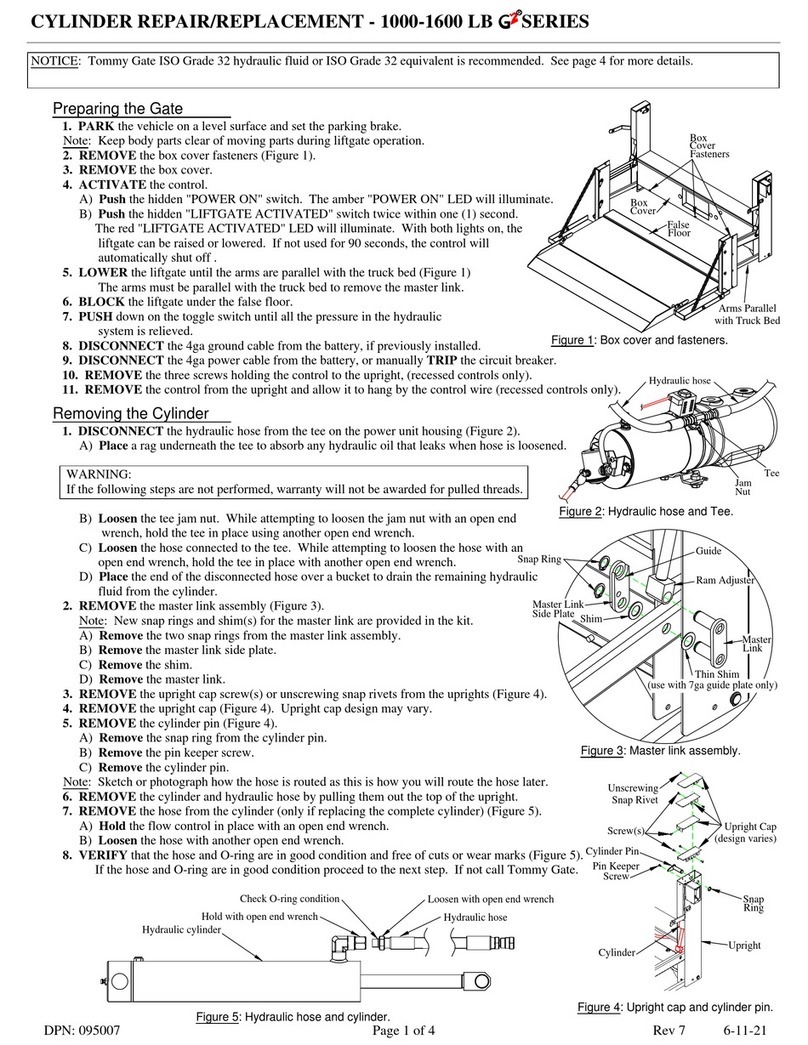
Tommy Gate
Tommy Gate Railgate 1600 Series User manual
Tommy Gate
Tommy Gate Railgate 1600 Series Owner's manual
Tommy Gate
Tommy Gate Cassette Series Owner's manual

Tommy Gate
Tommy Gate 650 Series Owner's manual
Tommy Gate
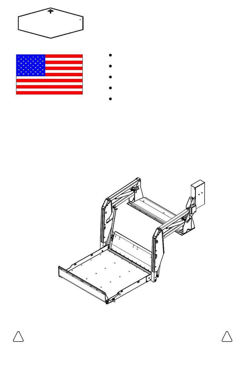
Tommy Gate G2 Dual Drive Original Series Owner's manual
Tommy Gate
Tommy Gate V2 Series User manual

Tommy Gate
Tommy Gate V2 Series Guide
Tommy Gate
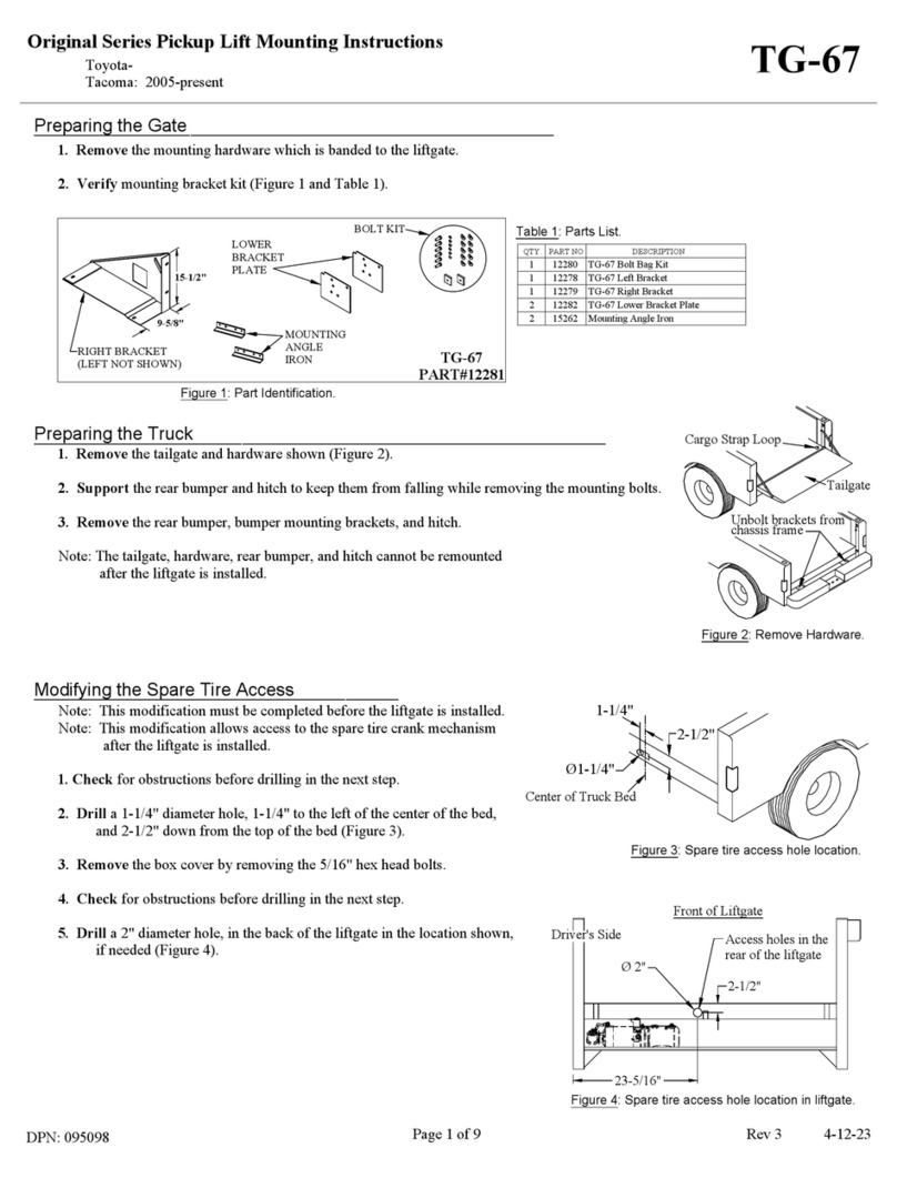
Tommy Gate Original TG-67 User manual
Popular Lifting System manuals by other brands

morse
morse 82H-124 Operator's manual

Braun
Braun NL955 Series Operator's manual

haacon
haacon 1889.10 quick start guide

Protekt
Protekt AT 252 instruction manual

R. Beck Maschinenbau
R. Beck Maschinenbau HS 600 operating manual

Nova Technology International, LLC
Nova Technology International, LLC NAS Series quick start guide

Genie
Genie Z-60/34 Operator's manual

Screen Technics
Screen Technics INTERFIT Vertical Up Lift instructions

Mortuary Lift
Mortuary Lift ULTIMATE 1000 instructions

Custom Equipment
Custom Equipment Hy-Brid 3 Series MAINTENANCE & TROUBLESHOOTING MANUAL

Custom Equipment
Custom Equipment Hy-Brid Lifts 2 Series Maintenance and troubleshooting manual

Hy-Brid Lifts
Hy-Brid Lifts HB-P3.6 MAINTENANCE & TROUBLESHOOTING MANUAL

BERG
BERG BeNomic EasyLeaf Technical manual

Powermate
Powermate LiftGate LG-3 Installation & operation manual

Snorkel
Snorkel TM12 Series Operator's manual

Terberg
Terberg OMNIDEKA Translation of the original instructions

Harmar Mobility
Harmar Mobility AL625 Installation & owner's manual

Rotary
Rotary SPO16 installation instructions


