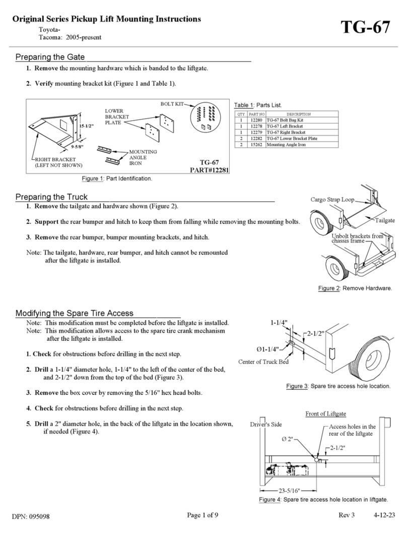
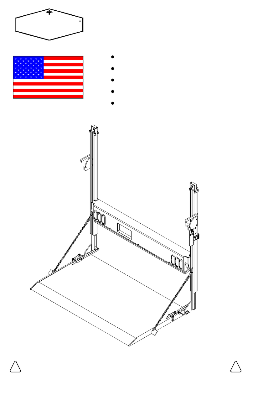
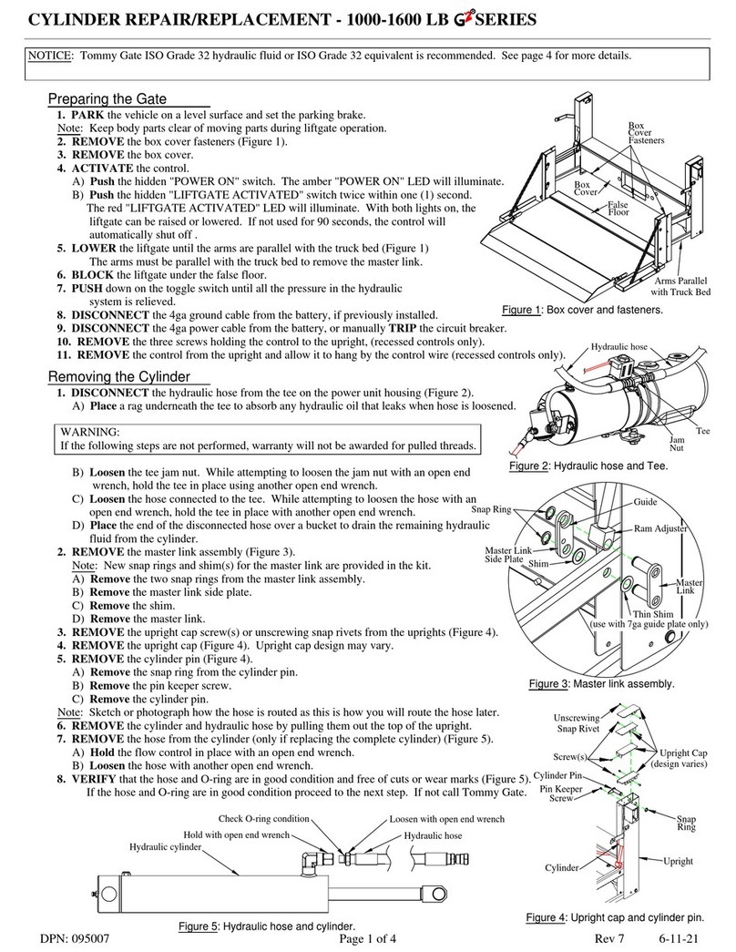
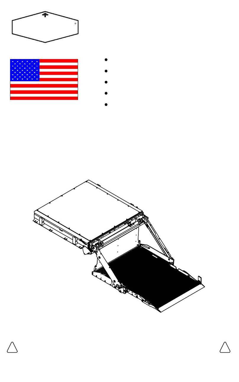
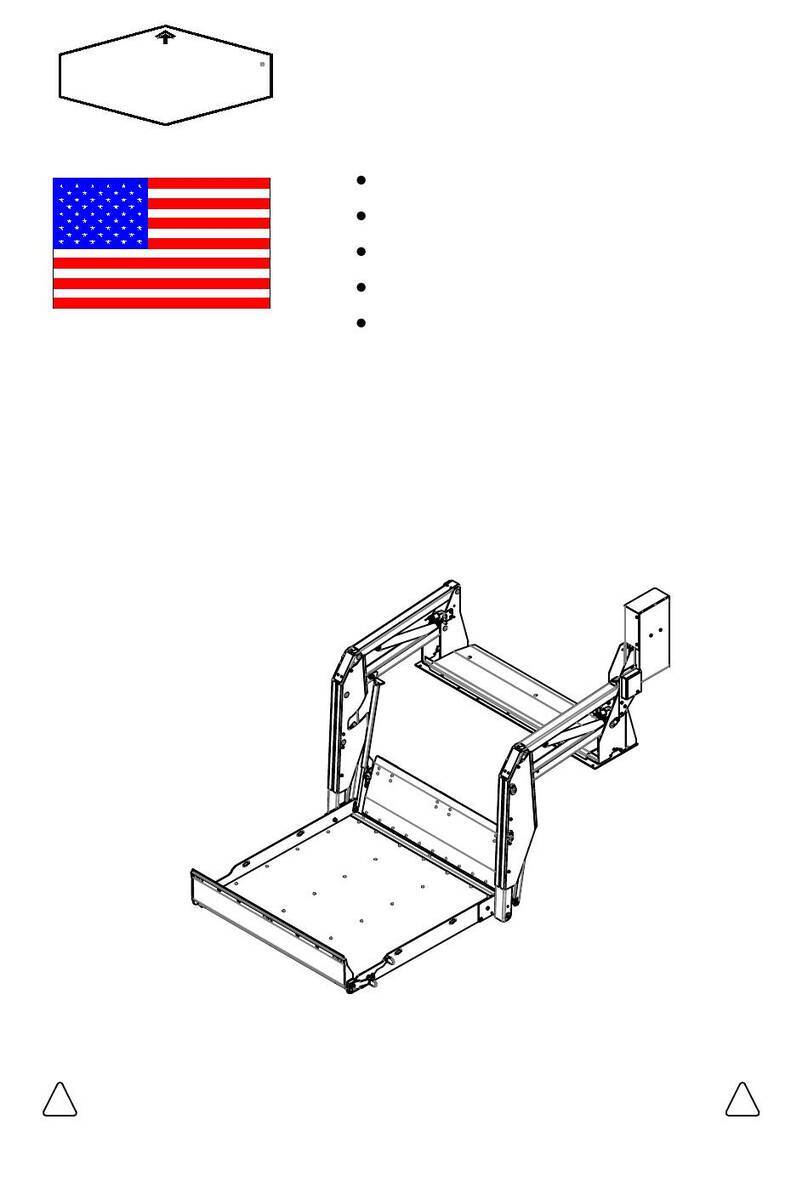
Tommy Gate G2 Dual Drive Original Series Owner's manual

and the Safety Compliance Certification Label located on the driver's door pillar.
Limitations. These loading limitations are outlined in the Vehicle Owner's Manual
Before installing or using this liftgate, please observe the Vehicle Loading
!
PLEASE KEEP IN VEHICLE
CAUTION
!
CAUTION
G2 SERIES
700-2000 LB CAPACITY
Woodbine, Iowa
· Safety Information
· Warranty Information
· Operator's Instructions
· Maintenance Instructions
· Parts List
OWNER'S / OPERATOR'S
MANUAL
DPN: 009120 Page 1 of 28 Rev 29 11-2-23

TABLE OF CONTENTS
DPN: 009120 Page 2 of 28 Rev 29 11-2-23
Introduction Page #
To the Owner\Operator-------------------------------------------------------------------- 3
Safety Decals
Location and Descriptions----------------------------------------------------------------- 4 - 6
Decal Replacement------------------------------------------------------------------------- 6
Operator's Instructions
G2 Series Terms and Method of Operation----------------------------------------------7
Operator's Instructions--------------------------------------------------------------------- 8
Latch Adjustment--------------------------------------------------------------------------- 9 - 10
Lift-N-Dump as a Dump Body----------------------------------------------------------- 11
Platform Drop Away Feature (Excludes 2000# TP Platform)------------------------ 12 - 13
Spare Tire Access (pickup liftgate only)------------------------------------------------ 14
Electrical Wiring Diagrams
Standard Fixed Control-------------------------------------------------------------------- 15
Optional Pendant Control----------------------------------------------------------------- 16
Ladder Logic/Wiring Diagram------------------------------------------------------------ 17
Maintenance and Service---------------------------------------------------------------- 18
Troubleshooting--------------------------------------------------------------------------- 19
Warranty
Standard Warranty-------------------------------------------------------------------------- 20
Warranty Claims Handling Procedure--------------------------------------------------- 20 - 21
Repair Parts List
Repair Parts Drawing---------------------------------------------------------------------- 22 - 23
Repair Parts List---------------------------------------------------------------------------- 24
Hydraulic Fluid Notice------------------------------------------------------------------- 25
Service Records---------------------------------------------------------------------------- 27
Contact Information---------------------------------------------------------------------- 28

maintenance and service information. Should you need repair or service information, contact
This is the safety alert symbol. It is used to alert you to potential personal
Safety is a primary concern in the design and manufacture of our products. Unfortunately,
Read this manual completely before using your gate. Operate and maintain your gate safely
injury hazards. Obey all safety messages that follow this symbol to avoid
proper training of the personnel who operate, transport, maintain and store this equipment. It
It has been said that "the best safety device is an informed, careful operator." We ask you
to be that kind of operator.
our efforts to provide safe equipment can be wiped out by a single careless act of an operator.
is your responsibility to use good judgment in the operation of this equipment.
as outlined in this manual. Be sure you read and understand all operating, safety,
avoided, may result in minor or moderate injury.
WARNING indicates a potentially hazardous situation which, if not
DANGER indicates an imminently hazardous situation which, if not
avoided, will result in death or serious injury.
avoided, could result in death or serious injury.
CAUTION indicates a potentially hazardous situation which, if not
Tommy Gate or an authorized distributor for assistance.
possible injury or death.
Accident prevention and safety are dependent upon the awareness, concern, prudence and
TO THE OWNER\OPERATOR
Note: This manual applies to both 42" and 50" travel lifts. If an instruction or illustration
is unique to either the 42" or 50" lift it will be so indicated. If it is not so indicated, an
instruction or illustration then applies to both the 42" and 50" travel lifts.
avoided, may result in property damage.
CAUTION indicates a potentially hazardous situation which, if not
DPN: 009120 Page 3 of 28 Rev 29 11-2-23
DANGER
WARNING
CAUTION
CAUTION

Located next to the control shield.
before operating equipment.
corner of the platform.
Located on the outside right-hand
Stand clear of all moving parts when opening,
will vary if your vehicle is on an incline.
Platform opening and closing forces/weights
raising or lowering platform.
Do not add any extension to original platform.
Never leave the platform down to be used as
Keep one hand on the platform when opening
moving parts
Keep away from
Located on the side of uprights
DANGER
a step.
and closing.
Decal No. 4
XXX lb or XXX kg
Rated Lift Capacity
9555
Decal No. 2
9523
Decal No. 3
Decal No. 5
1500 lbs. 9481
2000 lbs. 9480
1600 lbs. 9479
Do not modify lift or its safety
authorized distributor.
service parts installed by an
Use only Tommy Gate
needed, call Tommy Gate
If additional assistance is
at 712-847-8000
Do not exceed the rated lift
capacity-
features.
9524
WARNING
DECAL LOCATIONS AND DESCRIPTIONS
Read operator's manual
WARNING
Place in cab in a highly visible area.
Decal No. 1
REPLACE IF MISSING OR NOT READABLE
Locate and read all decals prior to operating gate
DPN: 009120 Page 4 of 28 Rev 29 11-2-23
1300 lbs. 9478
1000 lbs. 9477
700 lbs. 15885
750 lbs. 9453
9561
UNATTENDED. NEVER LEAVE PLATFORM
UNLATCHED WHEN LIFT IS NOT IN USE OR
PERSONNEL OR WHEELCHAIR LIFT.
EQUIPMENT MANUFACTURER.
PROVIDED BY THE ORIGINAL
AS NECESSARY WITH PARTS
SAFETY AND OPERATIONAL DECALS MUST BE ATTACHED AND LEGIBLE
FEATURES. ALL REPLACEMENT PARTS MUST BE OF ORIGINAL QUALITY, AND ALL
BY AN AUTHORIZED DISTRIBUTOR THAT IS FAMILIAR WITH ITS OPERATION AND SAFETY
ALL REPAIRS OR REINSTALLATIONS OF TOMMY GATE LIFTS SHOULD BE PERFORMED
TOMMY GATE
DO'S
FOR PROPER OPERATION .
* DO CHECK ALL SAFETY DEVICES
* DO NOT LEAVE PLATFORM OPEN, OR
FOR WEAR OR DAMAGE AND REPAIR
* DO FREQUENTLY CHECK CABLES
CHAINS, AND OTHER COMPONENTS
* DO NOT MOVE VEHICLE UNLESS GATE IS
IN LATCHED POSITION.
* DO READ OPERATOR'S INSTRUCTIONS.
* DO NOT SHOW CHILDREN OR
UNAUTHORIZED PERSONNEL HOW TO
TRAINING IN ITS OPERATION.
* DO STAND TO THE SIDE OF LIFTGATE
WHILE IT IS IN OPERATION.
THAN THE RATED CAPACITY OF THE LIFT.
* DO NOT TRY TO LIFT OR LOWER MORE
LIFT AS IT WILL VOID YOUR WARRANTY.
* DO NOT ADD TO OR REMOVE PARTS OF
INFORMATION.
* DO READ MAINTENANCE AND SERVICE
UNATTENDED.
* DO CLOSE AND LOCK LIFT IN CLOSED
POSITION WHEN NOT IN USE OR
* DO NOT ALLOW USE OF LIFT BY A
PERSON WHO HAS NOT HAD PROPER
* DO NOT RIDE OR PERMIT ANYONE TO
RIDE ON LIFT. THE LIFT IS NOT A
DO NOT'S
* DO CENTER YOUR LOAD ON PLATFORM.
DOWN TO BE USED AS A STEP.
* DO NOT MAKE ANY MODIFICATIONS TO
THE LIFT OR ITS SAFETY FEATURES.
OPERATE LIFT.
R

Decal No. 6
Located on left-hand upright inside the frame.
(Or on right hand side of lift and dump models.)
Located on box cover of gate.
Decal No. 9
DECAL LOCATIONS AND DESCRIPTIONS
Located on the inside of the main frame,
positioned over the top of the pump & motor unit.
the torsion spring and safety holder
Located on the upright next to
on models with torsion assist spring.
Decal No. 7
Decal No. 8
Located next to the control shield.
Decal No. 10
Located next to the control shield.
than its rated capacity.
Liftgate may lift more
Liftgate is not to be
used as a scale.
exceed the rated
Be aware of how much
is being lifted and never
capacity of the liftgate.
capacity of the vehicle.
is being hauled and
Be aware of how much
never exceed the rated
WARNING
9044
DPN: 009120 Page 5 of 28 Rev 29 11-2-23
Serial Number:
Part Number:
TOMMY GATE
The original
hydraulic lift
®
CAUTION
high tension
Spring under
9540
platform.
Center
Load
platform side to
side and front to
Center load on
This lift is not
wheelchair or
designed as a
personnel lift.
Do not ride the
WARNING
the lift.
in use or
secured.
untrained person to
platform should be
closed and latched
with control
When the lift is not
unattended, the
how to operate
children or others
Do not show
operate the lift.
Never allow
children or any
back.
9522
DANGER
9556
2) Disconnect positive battery cable(s).
1) Lower platform to ground or close and latch.
Before removing box cover do the following.

remaining back and smooth in place. Gently rub decal with a damp rag or sponge to smooth out bubbles.
To replace decal, clear area of grease and dirt with non-flammable solvent and soap and water. Allow to
If the liftgate is going to be painted, you need to mask the decals before painting. Remove the mask after
painting so the decals can be read clearly.
dry. To apply decal, peel off 1/2 of back. Hold decal squarely and apply to cleaned surface. Peel off
(The decal has a pressure-sensitive adhesive on the back.)
NOTE: When ordering Decals, please have Decal Numbers available.
DECAL REPLACEMENT
DECAL LOCATIONS AND DESCRIPTIONS
Decal No. 13
Located on the outside bottom left-hand
corner of the platform.
Placed on every lift and dump model.
STAND CLEAR WHEN
RELEASING LATCH
AND DURING DUMP
OPERATION
WARNING
CAUTION
platform folded and secured with both
The liftgate must be fully raised with the
liftgate when unpinning or unlatching the
Stand to the side, not behind or under the
insert latch lever. The dump platform will
Keep hands, feet, and limbs clear of a
Close, latch, and pin insert latch lever
Do not unpin or unlatch insert with hoist
LATCH
Located on the outside bottom left-hand
Placed on every lift and dump model.
UNLATCH
swinging insert.
when the dump body hoist is in the
completely lowered position only.
corner of the platform.
swing out.
Decal No. 11
lynch pins to the liftgate frame.
raised.
Placed on every lift and dump model.
Decal No. 14
Located on the outside top center of the platform
9124
9140
Placed on every lift and dump model.
corner of the platform.
Decal No. 12
Located on the outside top right-hand
Never unfold the platform,
the platform frame, and the
latch lever is latched and
unless both insert latch
pins are fully engaged in
Never use Lift-N-Dump as a liftgate when
the dump body hoist is raised.
action body hoist is used.
Hold down clamps must be used to secure
dump body to truck frame when a single
Stand to the side, not behind or under the
liftgate, when unfolding the platform.
9142
pinned.
9141
Pinned
Latched
CAUTION
DPN: 009120 Page 6 of 28 Rev 29 11-2-23
15731
WARNING: Cancer
and Reproductive Harm-
www.P65Warnings.ca.gov
Located on the side of the control.
Decal No. 15

Control
Hinge Arms
Platform
Sub Assembly
Folding Extension
Platform
(Used on Some Models)
Chain
(Used on Some Models)
Torsion Assist Spring
Cylinder
Box Cover
Hinge Tube
Latch
SERIES TERMS AND METHOD OF OPERATION
of Main Frame
Pump & Motor Inside
Main Frame
Assembly
Latch
Cylinder
!Caution:
Never leave the truck with the platform on the ground, partially raised, or open.
Never show children or unauthorized personnel how to operate the gate.
To prevent children or unauthorized personnel from operating the lift, be sure the gate is in the stored
position and both the driver's side and passenger's side latches are secured. Make sure the passenger's
side latch padlock is installed and the control is deactivated before leaving the truck unattended.
!Warning: The Tommy Gate is an industrial product for material handling only and is not to
be used as a personnel or wheelchair lift. Do not ride on the platform and always
stand clear of the platform when opening, raising or lowering.
Your Tommy Gate is connected to your vehicle battery. The vehicle battery powers a motor, coupled to a
hydraulic pump. This motor and pump combination is called a power unit. Flow from the pump retracts the
two cylinders attached to the upper arm assembly that lift the gate platform.
!Warning: Liftgate is not to be used as a scale. Liftgate may lift more than its rated capacity.
Be aware of how much is being lifted and never exceed the rated capacity of the
liftgate. Be aware of how much is being hauled and never exceed the rated
capacity of the vehicle.
The gate platform is lowered by gravity after an electric "lower" solenoid valve is activated and opened at the
power unit.
Tommy Gate's control incorporates a "Low Voltage" warning feature. A "Low Voltage" condition exists
when the "Power On" button is armed and 7 Volts or less is present at the power unit. This "Low Voltage"
feature is designed to warn the operator that there is a low voltage condition and that it should be corrected as
soon as possible. The amber "Power On" LED will blink to warn the operator of this condition. When this
light is blinking, it will not prevent the control from functioning to raise or lower the gate. In a "Low Voltage"
situation, whether the gate actually raises or lowers depends on how low the voltage is.
Caution:
Continuing to operate the the liftgate in the "Low Voltage" condition may result in failure of electrical
components in the power unit.
The low voltage condition may be caused by a weak battery, loose or corroded connections, improper ground,
or bad electrical cables. This condition may be corrected by just starting the vehicle or replacing the battery.
DPN: 009120 Page 7 of 28 Rev 29 11-2-23
R

OPERATOR'S INSTRUCTIONS
Step 1. To open the platform, go to the driver's side of the Tommy Gate,
push the latch to the side, off the platform pin, and rotate the
latch down. Proceed to the passenger's side of the Tommy Gate
and remove the latch padlock. Push the passenger's side latch to
the side, off the platform pin with one hand while holding
the top of the platform with your other hand. Pull the platform
open and step away from the platform as it opens.
Lift-N-Dump Models only (Figures 2 - 3)
!Caution:
Never use Lift-N-Dump as a liftgate when the dump body hoist is raised.
Hold down clamps must be used to secure dump body to truck frame when
a single action body hoist is used.
Never unfold the platform, unless both insert latch pins are fully engaged
in the platform frame, and the latch lever is latched and pinned.
To open the Lift-N-Dump platform, open the hasps
and remove the driver side lynch pin. Remove the
padlock on passenger side.
Step 2. If the gate is on an application with swing out doors,
you can open them at this time.
Step 3. Be sure to stand clear of the platform and all moving
parts when using the lift.
Figure 1
Figure 4
Figure 2-LND
Padlock
Platform
Lid End
Figure 3
Pin
Latch
Lynch
Pin Padlock
Latch
Latch Pin
Padlock
Latch
"POWER ON"
"LIFTGATE ACTIVATED"
Amber LED-
Enabled when "ON"
Enabled when "ON"
Red LED-
second to activate timer
Hidden Switch-
Press once to arm
"POWER ON"
Press twice within one
"LIFTGATE ACTIVATED"
Hidden Switch -
Step 4. To turn the control power on, press the "POWER ON" hidden
switch once, marked with white rings or circles (located between the
Tommy Gate logo and the toggle switch). You should see the amber
LED "POWER ON" light when the control is armed. To disarm the
control press the "POWER ON" hidden switch again. To activate the
control, press the "LIFTGATE ACTIVATED" hidden switch twice within
one second (located under the Tommy Gate logo). You should see the red
"LIFTGATE ACTIVATED" light when the control is activated. To lower
the platform, push the toggle switch down. To raise the platform, push the toggle
switch up. When you remove pressure from the toggle switch, the operation will
stop. After you have activated the control by pressing the "LIFTGATE
ACTIVATED" hidden switch twice within one second
(located under the Tommy Gate logo), you have
approximately 90 seconds to use the gate. If the gate is
not used for approximately 90 seconds, the "LIFTGATE
ACTIVATED" timer deactivates the control. If the gate is
used during the 90 seconds, the "LIFTGATE
ACTIVATED" timer automatically resets for an additional
90 seconds. To reactivate the timer, press the "LIFTGATE
ACTIVATED" hidden button twice within one second.
Step 5. After the platform is raised to the level of the vehicle's
floor and the load is removed, close the platform and folding
extension (if so equipped). The latch on the passenger's side
will secure itself. Install the latch padlock on the passenger's
side latch. Go to the driver's side and secure the latch.
DPN: 009120 Page 8 of 28 Rev 29 11-2-23

Center the platform latch pin vertically in the latch hole. Push the platform latch pin
toward the front of the truck so there is a 1/8" gap (Page 10, Figures 10 & 11) .
Tighten the platform latch pin with a 9/16" wrench and a screwdriver.
Check the spring tension on the driver's side and passenger's side latch springs as
shown (Page 10, Figures 8 & 9). The driver's side swing away latch spring should
measure 1" tall. Tighten or loosen if necessary. The passenger's side fixed latch
spring should measure 7/8" tall. Tighten or loosen if necessary.
Loosen the platform latch pin with a 9/16"
wrench and a screwdriver. The hole in
the platform is oversized to allow
the platform latch pin to be adjusted.
See exploded view drawing (Figure 7).
Close and latch the platform.
Hole is oversized for
adjustability.
Insert Screwdriver into
Platform Latch Pin Hole
Lock Nut
Platform
Latch Pin
Platform Latch
Pin Hole
Figure 7
Washer
Platform
LATCH ADJUSTMENT 700-2000 SERIES
DPN: 009120 Page 9 of 28 Rev 29 11-2-23
R
Upright Cap
Control
Screws
Make sure the liftgate is in the fully raised position.
Disconnect the #4 power cable from the positive side of the battery or manually trip the
circuit breaker. Remove the latch padlock from the passenger's side of the platform.
Unlatch the driver's side latch and then the passenger's side latch. Unfold the liftgate
platform.
Remove the Phillips head screws that hold the upright caps in place, then remove both
upright caps (Figures 5 & 6).
Remove the Phillips head screws that hold the control in place, then remove the control.
Inside of the Uprights
Upright Cap
Figure 6. Remove the upright cap screw.
Outside of the Uprights
Figure 5. Remove the upright cap and
control screws.
Upright
Cap
Screw
Upright
Cap
Screw

LATCH ADJUSTMENT 700-2000 SERIES
1" Driver's Side
Platform Latch Pin
78" Passenger's Side
Latch
Platform
Latch
Hole
18"
Upright
Latch Spring
Latch Spring
38 Lock Nut
38 Lock Nut
38 Bolt
Flat Washer
Latch
Latch
38 Bolt
Reinstall the control and upright caps on the uprights.
Reconnect the liftgate's main power cable
to the positive side of the battery or
re-engage the circuit breaker.
Install the latch padlock on the passenger's
side of the platform (Figure 12).
Latch
Platform
Latch
Hole
Platform Latch Pin
18"
Figure 8. Latch spring
Figure 10. Latch pin adjustment
42 inch travel lift.
Figure 9. Latch spring
Figure 11. Latch pin adjustment
50 inch travel lift.
Latch Pin
Padlock
Latch
Figure 12. Latch padlock
DPN: 009120 Page 10 of 28 Rev 29 11-2-23
R

UNLATCH
This Way To Release
Pull Insert Latch Lever
Insert Latch Lever
LATCH
! WARNING
Keep hands, feet, limbs and
body clear of a swinging insert.
! Caution:
Never show children or unauthorized personnel how to operate the gate.
To prevent children or unauthorized personnel from operating the gate before leaving the truck unattended be sure:
-the gate is in the stored position
-both the driver's side and passenger's side lynch pins are installed
-the insert latch handle is latched and pinned
-the control is deactivated.
Using the dump through feature.
Step 1. The liftgate must be fully raised with the platform folded and secured with both lynch pins installed.
Step 2. The dump body must be lowered completely to help relieve the pressure on the insert.
! Caution:
Never remove the latch pin from
the insert latch lever with the hoist raised.
Step 3. Remove the latch pin from the insert latch lever.
(see Detail B)
! Caution:
Never unlatch the insert with the hoist raised.
Step 4. Stand to the side, not behind or under the liftgate.
Unlatch the insert by pulling the insert latch lever
to the side. (see Detail B) The insert will swing out.
Closing and latching the insert.
Step 1. The dump body must be lowered completely.
Step 2. Push on the bottom of the insert to close.
Step 3. Move the insert latch lever to the latch position. (see Detail B)
Step 4. Install the latch pin in the insert latch lever.
Both lynch pins must
be installed before
using the dump
through feature
Lynch Pin
Latch
Platform
Latch Pin
SERIES LIFT-N-DUMP AS A DUMP BODY TAILGATE
Figure 13
Detail A
Insert
A
B
Detail B
Lynch Pin
Figure 14
Bolts
Adjusting the latches. (Figure 14)
Step 1. Close and latch the platform.
Step 2. Loosen the bolts.
Step 3. Center the tongue over the latch eye.
Step 4. Tighten the bolts.
Step 5. Repeat on other side.
Lynch Pin
Insert
Insert
DPN: 009120 Page 11 of 28 Rev 29 11-2-23
R
Latch Eye
Tongue

PLATFORM DROP AWAY FEATURE
Not available for 2000# Treadplate Platforms
Installing platform drop away pin (Figure 15).
1. Insert the platform drop away pin through the
existing 3/8" hole in the upright back.
2. Fasten the pin to the upright using the
supplied 3/8" nut.
Platform drop
away pin
3/8" Hole
3/8" Nut
Upright
Back
Preparing chain for platform drop away feature (Figure 16 & 17).
1. Position the platform and platform chain as
shown in Figure 17.
2. Unhook the platform by rotating it over the flat side
of the pin.
Unhook both
chains from the
sub assembly pins.
Mark cloth cover
and cut 1" slit.
Push platform down
against spring tension.
Figure 15
Figure 16
DPN: 009120 Page 12 of 28 Rev 29 11-2-23
Pin flat side.
Figure 17
!Caution - The platform may spring back with
great force if released under pressure.
3. Push the platform down and pull driver side
chain toward the drop away pin on the upright.
4. Mark the position of the cloth cover
that is next to the drop away pin.
5. Slowly release the platform allowing
the spring tension to lessen.
6. Cut a 1" slit in the cloth cover.

PLATFORM DROP AWAY FEATURE
Not available for 2000# Treadplate Platforms
Using platform drop away feature (Figure 18).
1. Unhook both platform chains from the
sub-assembly pins.
2. Pull chain link through slit cut in driver
side chain cover.
!Caution - The platform may spring back with
great force if released under pressure.
3. Push the platform down and hook exposed
link over drop away pin on the upright.
Caution - If equipped the platform flipper may fall
open and contact the ground if the ball locks
on the platform are not in good working order.
Unhook both
chains from the
sub assembly pins.
Hook exposed chain
link to drop away pin
on driver side upright.
Push platform down
against spring tension.
Disabling platform drop away feature.
1. Reverse order of above instructions.
Figure 18
DPN: 009120 Page 13 of 28 Rev 29 11-2-23

DPN: 009120 Page 14 of 28 Rev 29 11-2-23
SPARE TIRE ACCESS (pickup liftgate only)
Accessing the Spare Tire
There are holes in the back of the liftgate which provide access to the factory spare tire crank
on some pickup liftgates. The following will help you locate the spare tire access hole for your
application.
1. Remove the box cover by removing the 5/16" hex head nuts (Figure 19).
2. Locate the access hole for your application using Figure 20 and Table 1.
3. Insert the vehicle spare tire crank rod through the access hole
The spare tire crank rod is inserted at an angle, toward the center of the truck.
4. Rotate the vehicle spare tire crank rod to raise or lower the spare tire.
5. Reinstall the box cover and 5/16" hex head nuts when finished.
Figure 20
Access holes
in the rear of
the liftgate
(3) 5/16" Hex
Nuts
Figure 19
Table 1
24 7
16
36 1
16 3813
16
3013
16
3913
16
Driver's Side Front of Liftgate
D
E
F
C
B
421
8
225
8
A
Pickup Application Access
Hole
F-150 & F-250 LD (1997-2003) A
Super Duty Series (1999-2007) A
Nissan Titan (2004-Present) B
Toyota Tundra (2007-Present) C
Chevy/GMC Short Box (2007-2019) D
Chevy/GMC 1500 Long Box (2019)
Except "LD" or "Limited" D
Chevy/GMC 1500-3500 (2020-Present) D
Chevy Colorado/GMC Canyon
(2015-Present) D
F-150 (2004-Present) D
Pickup Application Access
Hole
Super Duty Series (2008-2016) D
Ford Ranger (2019-2023) D
Chevy/GMC Long Box (2007-2019)
Except 2019 1500 Long Box E
Chevy/GMC 1500 "LD" or "Limited"
Long Box (2019) E
Super Duty Series (2017-Present) E
Dodge/Ram (2003-2018) F
Ram 1500 "Classic" (2019-2022) F
Ram 2500/3500 (2019-Present) F
Ram 1500 (2019-Present) Except "Classic" G
G

"RAISE/LOWER"
INDICATES LOW
VOLTAGE CONDITION
BLINKING AMBER LED
TOGGLE SWITCH
CONTROL OPERATION
"LIFTGATE ACTIVATED" HIDDEN
"POWER ON" HIDDEN
DN
UP
"LIFTGATE ACTIVATED"
SWITCH - PRESS TWICE
WITHIN ONE SECOND TO
RED LED - ENABLED WHEN
DISARM
SWITCH - PRESS ONCE TO
ARM, PRESS AGAIN TO
ACTIVATE TIMER
"ON"
ENABLED WHEN "ON"
"POWER ON" AMBER LED-
IMPORTANT
PLEASE READ AND FOLLOW ALL
DIRECTIONS BEFORE PROCEEDING
IMPORTANT
WELDING NOTE !!! DISCONNECT ALL BATTERY CABLES.
ALWAYS DISCONNECT THE GROUND CABLE FIRST. ATTACH THE
WELDING GROUND TO THE TRUCK RATHER THAN THE LIFTGATE.
IMPORTANT
NOTE !!! IF GATES ARE NOT WIRED
IN ACCORDANCE WITH THIS DIAGRAM
YOUR WARRANTY WILL BE VOID.
ELECTRICAL WIRING DIAGRAM
Standard Fixed Control
FIREWALL THROUGH MOUNTING HOLES
ATTACH TO VEHICLE FENDER OR
"AUX" TERMINAL
"BAT" TERMINAL
DN
UP
NEG.
-POS.
BATTERY
VEHICLE
+
COMMON GROUND
PUMP AND MOTOR
GROUND CABLE
AWG #4
GROUND CABLE
AWG #4
AWG #4
MAIN POWER CABLE
AWG #4
MAIN POWER CABLE
CIRCUIT BREAKER AND
150 AMP MANUAL RESET
MASTER DISCONNECT
"LOWER" SOLENOID
VALVE
YELLOW, RED, BLACK,
OR BROWN - "LOWER"
"RAISE" SOLENOID
MOTOR CONTACTOR
AWG #18 WIRES
BLACK - GND.
BROWN - "LOWER"
HEAT SHRINK
BUTT CONNECTOR
GREEN -
"RAISE"
+12VDC SUPPLY
FOR CONTROL
SYSTEM
RED -
DPN: 009120 Page 15 of 28 Rev 29 11-2-23
INLINE FUSE
QUICK DISCONNECT

SOCKET END
COLE HERSEE
BLACK
NO WIRE
BROWN
NO WIRE
GREEN
COLOR
WIRE
INDICATES LOW
VOLTAGE CONDITION
BLINKING AMBER LED
"RAISE/LOWER"
TOGGLE SWITCH
RT
A
GD RED
TM
LT
POSITION
S
DISARM
DN
"LIFTGATE ACTIVATED" HIDDEN
CONTROL OPERATION
UP
GREEN
NO WIRE
NO WIRE
LT
RED
GD
TM
BROWN
WIRE INSERTION SIDE
CONNECTOR BACK VIEW
RT
A
BLACK
S
"LIFTGATE ACTIVATED"
ENABLED WHEN "ON"
RED LED - ENABLED WHEN
"POWER ON" AMBER LED-
SWITCH - PRESS TWICE
WITHIN ONE SECOND TO
"POWER ON" HIDDEN
SWITCH - PRESS ONCE TO
ARM, PRESS AGAIN TO
ACTIVATE TIMER
"ON"
IMPORTANT
PLEASE READ AND FOLLOW ALL
DIRECTIONS BEFORE PROCEEDING
IMPORTANT
WELDING NOTE !!! DISCONNECT ALL BATTERY CABLES.
ALWAYS DISCONNECT THE GROUND CABLE FIRST. ATTACH THE
WELDING GROUND TO THE TRUCK RATHER THAN THE LIFTGATE.
IMPORTANT
DN
UP
NOTE !!! IF GATES ARE NOT WIRED
IN ACCORDANCE WITH THIS DIAGRAM
YOUR WARRANTY WILL BE VOID.
ELECTRICAL WIRING DIAGRAM
Optional Pendant Control
FIREWALL THROUGH MOUNTING HOLES
ATTACH TO VEHICLE FENDER OR
"AUX" TERMINAL
"BAT" TERMINAL
NEG.
-POS.
BATTERY
VEHICLE
+
COMMON GROUND
PUMP AND MOTOR
GROUND CABLE
AWG #4
GROUND CABLE
AWG #4
AWG #4
MAIN POWER CABLE
AWG #4
MAIN POWER CABLE
CIRCUIT BREAKER AND
150 AMP MANUAL RESET
MASTER DISCONNECT
"LOWER" SOLENOID
VALVE
YELLOW, RED, BLACK,
OR BROWN - "LOWER"
"RAISE" SOLENOID
MOTOR CONTACTOR
AWG #18 WIRES
BLACK - GND.
BROWN - "LOWER"
HEAT SHRINK
BUTT CONNECTOR
GREEN -
"RAISE"
+12VDC SUPPLY
FOR CONTROL
SYSTEM
RED -
DPN: 009120 Page 16 of 28 Rev 29 11-2-23
INLINE FUSE
QUICK DISCONNECT

DPN: 009120 Page 17 of 28 Rev 29 11-2-23
LADDER LOGIC/WIRING DIAGRAM
"Raise" Contactor
Legend
Contactor - Normally Open Contacts
Motor
Solenoid/Contactor - Coil
Circuit Breaker
Battery Cable
Wire
Grounded through pump body.
"Lower"
Valve
"Raise"
Contactor
M
UP
DOWN
M
Eyelet Terminal
Splice
Red (12V)
Blue (24V)
Green
Brown
Black
Black
Red
Battery
+12V
or +24V
Battery
GND
Pump
Motor
Fixed Control
Red
Red with Black Stripe
On/Off/
Activate
24V
M
Pump
Motor
BKBK RD/BK
Abbreviations
BK: Black
RD/BK: Red with Black Stripe
Fuse
Fuse
Red Red
Quick Disconnect
Red
Violet
BK
"Raise"
Contactor
Green Violet
24V

DPN: 009120 Page 18 of 28 Rev 29 11-2-23
upright caps to grease the
NOTE: Lower the liftgate to the
ground and remove the
All installations, re-installations, and repairs of Tommy Gates should be performed by a qualified
authorized distributor that is familiar with its operation and safety features. All replacement parts
must be of original quality, and all safety and operational decals must be attached. No modifications
are allowed to a Tommy Gate product unless authorized in writing by the Engineering Department at
Tommy Gate.
As is with any mechanical product, a preventive maintenance program needs to be followed in order
to keep it in its best operating condition. Please review this information and if you should have any
questions, please call (712) 847-8000. Please have your model number and serial number available.
The Tommy Gate needs to be serviced every 120 days or 1500-2000 cycles, whichever comes first.
(A) Inspect platform chains for any wear. Replace immediately if either is found to be worn.
(B) Check the oil level in the reservoir. With the liftgate platform at the bottom of its travel,
the fluid should be two-thirds full. BE SURE THE CYLINDERS ARE COMPLETELY
EXTENDED.
(C) Check for leaks from the cylinders, hoses, and all fittings (replace or repair if found to be
leaking).
(D) Grease all cylinder pivots with an ample amount of grease (every 120 days).
Do not grease composite bushings.
(E) Replace any worn or missing parts before the liftgate is put back into service.
(F) If needed, adjust platform latches which are designed to hold
the liftgate in a properly stored position.
(G) Check for cracks in all welds (repair if needed).
(H) Check for wear at all pivot points.
(I) Check all electrical connections.
(clean or repair if needed)
(J) Replace fuses, if needed.
Check electric cables for worn or
damaged insulation.
(K) Replace or clean safety decals,
so that they are legible.
(L) Check for proper operation
of the control.
locations shown.
MAINTENANCE AND SERVICE INFORMATION
Cylinder pivot
Cylinder pivot
Composite bushing

TROUBLESHOOTING 700-2000 LB SERIES
DPN: 009120 Page 19 of 28 Rev 29 11-2-23
R

The Tommy Gate Company provides a limited warranty against faulty materials or
workmanship. Series Tommy Gates are warrantied for two (2) full years from the
date of user purchase against faulty materials or workmanship.
All affected parts must be returned to the factory prepaid - with full credit issued for
those found to be defective. Warranty replacement parts will be shipped from the
factory prepaid.
Labor charges to install warranty replacement parts shall be paid in accordance with
Tommy Gate's estimated repair time guide and a flat hourly rate established by
Tommy Gate. DEVIATION FROM THE WARRANTY TIMES LISTED
MUST BE AUTHORIZED BY TOMMY GATE COMPANY IN ADVANCE.
The warranty does not include damage resulting from improper installation
procedures. Parts must be installed according to Tommy Gate Company's
specifications.
Tommy Gate Company will not pay labor for removing other equipment to gain
access to Tommy Gate Equipment. Tommy Gate Company will not pay labor for
time on the road to and from a service call.
Tommy Gate Company reserves the right to disallow or reduce claims for parts
which have been damaged due to misuse, abuse, accidents or improper shipping; or
parts which have been incorrectly or unnecessarily replaced.
The warranty is void if the product has been subject to other than normal use.
THERE ARE NO WARRANTIES, EXPRESS OR IMPLIED, INCLUDING
THE WARRANTY OF MERCHANTABILITY OR A WARRANTY OF
FITNESS FOR A PARTICULAR PURPOSE EXTENDING BEYOND THAT
SET FORTH ABOVE.
The following procedures are required when an authorized distributor submits a
warranty claim for a defective Tommy Gate part:
1. Before any expense is incurred, but after the problem has been diagnosed, the
authorized distributor should contact Tommy Gate Company's Warranty
Department to discuss the problem and its correction.
2. If it is determined that the condition is potentially covered by Tommy Gate
Company's warranty, the authorized distributor will receive instructions on
how to proceed. A decision will be made to either repair or replace the
product or part in question.
3. If the product or parts are to be repaired, the authorized distributor will receive
a WARRANTY REQUEST NUMBER.
B. WARRANTY CLAIMS HANDLING PROCEDURE:
A. STANDARD WARRANTY
WARRANTY GUIDELINES
DPN: 009120 Page 20 of 28 Rev 29 11-2-23
R
Other manuals for G2 Dual Drive Original Series
1
Table of contents
Other Tommy Gate Lifting System manuals

Tommy Gate
Tommy Gate 650 Series Owner's manual

Tommy Gate
Tommy Gate V2 Series User manual

Tommy Gate
Tommy Gate Original TG-67 User manual

Tommy Gate
Tommy Gate V2 Series Guide
Tommy Gate
Tommy Gate Railgate 1600 Series User manual

Tommy Gate
Tommy Gate Railgate 1600 Series Owner's manual

Tommy Gate
Tommy Gate Cassette Series Owner's manual

Tommy Gate
Tommy Gate G2 dual drive G-330 User manual