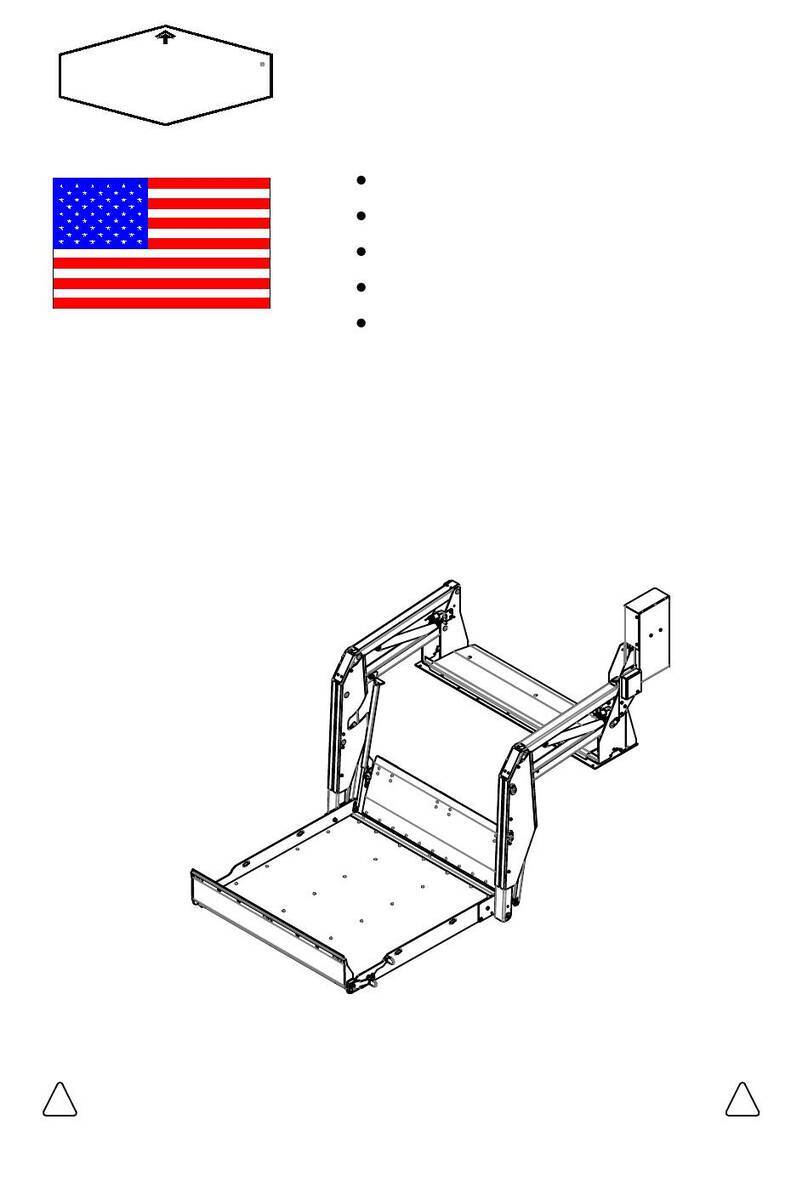
Tommy Gate V2 Series Guide

V2 Cylinder Repair or Replacement Instructions
DPN: 095265 Page 1 of 5 Rev 3 3-15-19
These instructions will aid you in repairing or replacing the cylinder(s) on a Tommy Gate V2 series liftgate and are used for multiple
kits. Locate your kit below and verify its contents.
Figure 1: V2 Complete Cylinder Part Identification
2 000737 CYLINDER COMPLETE W/ LOCK-V21 015177
QTY. DESCRIPTIONPART NO.
3/8-16x1" BHCS GR5-ZINC PLATED
000575 3/8" USS FLAT WASHER2
Table 1: Part List
Cylinder Complete
3/8" Flat Washer
3/8-16x1" Bolt
Kit Number 015876
Figure 2: V2 Cylinder Shaft Part Identification
2 000737
CYLINDER SHAFT COMPLETE-V21 015339
QTY. DESCRIPTIONPART NO.
3/8-16x1" BHCS GR5-ZINC PLATED
000575 3/8" USS FLAT WASHER2
Table 2: Part List
Cylinder Shaft Complete
3/8" Flat Washer
3/8-16x1" Bolt
Kit Number 015877
Spiral Ring
1 015175 1-5/8" INTERNAL SPIRAL RING-V2
Figure 3: V2 Cylinder Seal Part Identification
2 000737
ASSEMBLED V2 PISTON1 015878
QTY. DESCRIPTIONPART NO.
3/8-16x1" BHCS GR5-ZINC PLATED
000575 3/8" USS FLAT WASHER2
Table 3: Part List
Kit Number 015880
1 015175 1-5/8" INTERNAL SPIRAL RING-V2
3/8-16x1" Bolt
3/8" Flat Washer
5/8-18 Hex Nut
Piston
Guide Bushing
Spiral Ring
Protective Sleeve
1 015879 ASSEMBLED V2 GUIDE BUSHING
1 000552 5/8-18 SAE HEX FIN NUT
000763 CYL SHAFT PROTECTIVE SLEEVE1
Assembly Plug
Assembly Plug
013675 CYLINDER PORT ASSEMBLY PLUG1
009089 16-14 HEAT SHRINK BUTT CONNECTOR2
Butt Connector
015522 HEX PIN (V2) ZINC PLATED2009077 3/16"x7-1/2" CABLE TIE1
HEX PIN (V2) ZINC PLATED
009077 3/16"x7-1/2" CABLE TIE10155222
HEX PIN (V2) ZINC PLATED
009077 3/16"x7-1/2" CABLE TIE10155222
Hex Pin
Zip Tie
Zip Tie
Hex Pin
Hex Pin
Zip Tie

V2 Cylinder Repair or Replacement Instructions
1. Lower the liftgate to the ground.
2. Disconnect the 4 GA. power cable from the positive side of the battery (Customer Connection Point on the driver seat
pedestal on Ford Transit) or manually Trip the circuit breaker.
3. Remove and Discard the button head bolts from pins "A" and "B" (Figure 4).
4. Place a rag or piece of cardboard in the lower arm to protect the paint from the cylinder vent plug (Figure 4).
5. Remove and Discard pin "A" (Figure 4).
6. Rotate and Secure the upper arm out of the way (Figure 5).
7. Connect the 4ga power cable to the positive side of the battery (Customer Connection Point on the driver seat pedestal on
Ford Transit) or manually Engage the circuit breaker.
8. Push down on the toggle switch and Push in on the cylinder shaft to fully collapse the cylinder.
9. Disconnect the 4 GA. power cable from the positive side of the battery (Customer Connection Point on the driver seat
pedestal on Ford Transit) or manually Trip the circuit breaker.
10. Remove the hose from the cylinder lock (Figure 5).
11. Remove the coil from the cylinder lock (Figure 5).
12. Cut the coil wires 2" to 3" from the coil.
Complete this step only if replacing the coil.
Note: Support the lower arm in the next steps to keep if from falling.
13. Remove and Discard pin "B" (Figure 4).
14. Remove the cylinder.
15. Insert new pin "B" through outboard upright and far enough into lower arm to support the lower arm (Figure 5).
16. Remove and Save the cylinder lock from the cylinder (Figure 5), if reusing it for this repair.
Removing the Cylinder
DPN: 095265 Page 2 of 5 Rev 3 3-15-19
Figure 4: Pin Removal. Figure 5: Removing Cylinder.
Upper Arm
Lower Arm
Cylinder
Pin "A" and Button Head Bolt
Pin "B" and Button Head Bolt
Cylinder
Cylinder Lock
Coil
Cylinder Shaft
Upper Arm
Hose
Button Head Bolt
Button Head Bolt
Other side similar.
Other side similar.
Upright
Upright

Note: If you are replacing the complete cylinder, proceed to Installing the Cylinder.
1. Pull the cylinder shaft out to allow access to the spiral retaining ring.
2. Remove the cylinder vent plug (Figure 6).
3. Remove the spiral retaining ring (Figure 6).
4. Pull the cylinder shaft assembly out the end of the cylinder tube.
Note: This step could require significant force.
5. Inspect the inside of the cylinder tube.
a. Check for any scoring.
b. Check for any burrs on the spiral retaining ring groove and cylinder vent port.
6. Deburr the inside of the cylinder tube, if necessary, with a 240 grit flapper wheel or sand paper.
7. Clean the cylinder tube of all debris.
Disassembling the Cylinder
DPN: 095265 Page 3 of 5 Rev 3 3-15-19
Note: If you are replacing the complete cylinder shaft assembly, proceed to Installing the Cylinder Shaft.
The recommended hydraulic oil for this liftgate is ISO grade 32, Dexron, or equivalent.
1. Hold the shaft in a vice, using the cardboard tube provided as a protective barrier.
2. Remove and Discard the old nut.
3. Remove and Discard the piston and guide bushing.
4. Inspect the cylinder shaft for nicks or scarring and
replace if damaged.
5. Check the cylinder shaft threads for damage and
replace if damaged.
6. Clean the cylinder shaft and tube of all debris.
7. Lubricate the inside of the guide bushing with the recommended hydraulic oil.
8. Lubricate the cylinder shaft with the recommended hydraulic oil.
9. Install the guide bushing on the cylinder shaft as shown in (Figure 7).
A twisting motion will aid installation.
10. Install the piston and nut in the order and orientation shown in (Figure 7).
A twisting motion is required to avoid o-ring damage.
11. Tighten the nut to 80 ft-lbs while holding the ram adjuster in a vice.
Rebuilding the Cylinder
V2 Cylinder Repair or Replacement Instructions
Figure 7: Cylinder shaft assembly.
Guide Bushing
Piston
Nut Cylinder Shaft
Figure 6: Cylinder disassembly.
Cylinder Tube
Spiral Retaining Ring
Cylinder Shaft
Vent Plug
Cylinder Shaft Assembly
Ram Adjuster
Seal Flare Towards Nut

Figure 8: Cylinder assembly.
Installing the Cylinder Shaft Assembly
Note: The recommended hydraulic oil for this liftgate is ISO grade 32, Dexron, or equivalent.
1. Install the hole plug tool into the vent plug hole on the cylinder tube (Figure 8).
The end of the hole plug tool must be flush with the inside wall of the cylinder tube. If this is
not done or done incorrectly the seal will be cut when you install the cylinder shaft assembly in
the cylinder tube and THE CYLINDER WILL LEAK.
2. Check to make sure the hole plug tool is installed correctly. Run your finger over the plug on the inside
of the cylinder tube and check for any burrs that might cut or nick the cylinder seal.
3. Lubricate the piston, guide bushing, and the inside of the cylinder tube with the
recommended hydraulic oil.
4. Install the piston into the cylinder tube (Figure 8).
5. Install the guide bushing into the cylinder tube (Figure 8).
6. Install the spiral retaining ring in the spiral retaining ring groove.
7. Install the cylinder lock on the cylinder (Figure 8).
8. Remove the hole plug tool from the vent plug hole.
9. Install the vent plug in the vent plug hole.
Do not overtighten the vent plug, this could damage the piston.
DPN: 095265 Page 4 of 5 Rev 3 3-15-19
Installing the Cylinder
1. Insert cylinder into lower arm at pin "B".
2. Install pin "B" from the outboard side, through the lower arm, cylinder and uprights (Figure 9).
3. Attach the hose to the elbow on the cylinder lock.
4. Install the coil on the cylinder lock (Figure 9).
5. Cut the new coil wires to reach yellow wires previously cut, and Splice into the wiring harness.
Complete this step only if replacing coil.
6. Insert new pin "A" from the outboard side, through the vertical arm, upper arm
and cylinder (Figure 9).
7. Secure pins "A" and "B" with new button head bolts and flat washers (Figure 9).
8. Pull excess hose towards center of liftgate (under cover sheet). Excess
hose will kink when liftgate is raised if left in the upright.
9. Remove rag or cardboard previously placed in lower arm.
10. Connect the 4ga power cable to the positive side of the battery
(Customer Connection Point on the driver seat pedestal on
Ford Transit) or manually Engage the circuit breaker.
11. Run the liftgate through 3-4 complete cycles to remove
air from the system.
12. Check for leaks and Repair as needed.
V2 Cylinder Repair or Replacement Instructions
Spiral Retaining Ring Groove
Guide Bushing
Spiral Retaining Ring
Piston
Cylinder Tube
Cylinder Shaft
Figure 9: Installing cylinder.
Cylinder Lock
Coil
Upper Arm
Lower Arm
Cylinder
Pin "A" and Button Head Bolt
Pin "B" and Button
Cylinder Lock
Coil
Vertical Arm
Hole Plug
Cylinder Tube
Inside Wall
Cylinder Tube
Vent Plug
Hole
Tool
Head Bolt
Upright

DPN: 095265 Page 5 of 5 Rev 3 3-15-19
V2 Cylinder Repair or Replacement Instructions
Finishing the Repair
Note: The recommended hydraulic oil for this liftgate is ISO grade 32, Dexron, or equivalent.
1. Lower the platform until the platform taper touches the ground.
2. Disconnect the 4 GA power cable from the positive side of the battery
(Customer Connection Point on the driver seat pedestal on Ford Transit) or manually Trip the circuit breaker.
3. Remove the pump box cover by removing five (5) thumb or hex screws (Figure 10).
4. Check if the reservoir is at least 3/4 full, if it is, Skip to Step 8.
5. Remove the vent plug from the pump reservoir (Figure 11).
6. Add enough recommended hydraulic oil to fill the reservoir 3/4 full.
(The platform should be on the ground at this point or the reservoir will be overfilled.)
7. Install the vent plug in the pump reservoir.
8. Install the pump box cover and screws.
9. Connect the 4ga power cable to the positive side of the battery
(Customer Connection Point on the driver seat pedestal on Ford Transit) or manually Engage the circuit breaker.
10. Raise and Store the platform.
(3) Pump Box
Cover Screw
(2) Pump Box
Cover Screw
Vent plug
Figure 11: Vent plug.
Figure 10: Pump Box.
Pump Box Cover
Other manuals for V2 Series
2
Table of contents
Other Tommy Gate Lifting System manuals
Tommy Gate
Tommy Gate V2 Series User manual

Tommy Gate
Tommy Gate G2 Dual Drive Original Series Owner's manual

Tommy Gate
Tommy Gate Railgate 1600 Series Owner's manual

Tommy Gate
Tommy Gate 650 Series Owner's manual

Tommy Gate
Tommy Gate G2 dual drive G-330 User manual

Tommy Gate
Tommy Gate Original TG-67 User manual

Tommy Gate
Tommy Gate Cassette Series Owner's manual

Tommy Gate
Tommy Gate Railgate 1600 Series User manual