Fuji Electric MICREX-SX series User manual

series
USER’S MANUAL
SPF General Purpose Communication
FEH528b

Preface
Thank you for purchasing Fuji Electric Programmable Controller MICREX-SX SPF Series SPF.
This User’s Manual describes the specications of the SPF general purpose communication (RS-232C, RS-485).
This manual consists of General section (Page name with G), Hardware section (Page name with H), and Software section (Page
name with S).
Read this manual carefully to ensure correct operation and also read the corresponding user’s manuals listed below.
Notes
1. This manual may not be reproduced in whole or part in any form without prior written approval by the manufacturer.
2. The contents of this manual (including specifications) are subject to change without prior notice.
3. If you find any ambiguous or incorrect descriptions in this manual, please write them down (along with the manual No.
shown on the cover) and contact FUJI.
* In addition to the above manuals, the following Fuji Electric Co.,Ltd.site offers various manuals and technical documents
associated with MICREX-SX series.
URL http://www.fujielectric.com
Title Manual No. Contents
User’s Manual Hardware,
MICREX-SX series SPF
FEH526 Describes the system conguration, hardware specications and
operations of units in the MICREX-SX series SPF.
User’s Manual Instructions (Standard),
MICREX-SX series SPF
FEH524 Describes the memory specications and instructions specic to
SPF series.
User’s Manual Instructions (Standard),
MICREX-SX series SPH
FEH588 Describes the memory, language and system denitions of the
MICREX-SX series SPH (SX-mode, Standard loader).
User’s Manual SX-Programmer Standard
<Reference>, MICREX-SX series
FEH598 Describes the functions and the operations of SX-Programmer
Standard.
User’s Manual Instructions (Expert),
MICREX-SX series SPF
FEH525 Describes the memory specications and instructions specic to
SPF series.
User’s Manual Instructions (Expert),
MICREX-SX series SPH
FEH200 Describes the memory, language and system denitions of the
MICREX-SX series SPH (SX-mode, Expert loader).
User’s Manual SX-Programmer Expert
(D300win) <Reference>, MICREX-SX series
FEH257 Describes the functions and the operations of SX-Programmer
Expert.

Safety Precautions
Be sure to read the "Safety Precautions" thoroughly before using the module.
Here, the safety precautions items are classied into "Warning" and "Caution".
Warning
Caution
: Incorrect handling of the device may result in death or serious injury.
: Incorrect handling of the device may result in minor injury or physical damage
.
Even some items indicated by "Caution" may result in a serious accident.
Both safety instruction categories provide important information. Be sure to strictly observe these instructions.
Warning
Neve touch any part of charged circuits as terminals and exposed metal portion while the power is turned ON.
It may result in an electric shock to the operator.
Turn OFF the power before mounting, dismounting, wiring, maintaining or checking, otherwise, electric shock, erratic
operation or troubles might occur.
Place the emergency stop circuit, interlock circuit or the like for safety outside the PLC. A failure of the PLC might break
or cause problems to the machine.
When using an expansion right side unit, be sure to mount a healthy unit to stop the SPF system with a fatal fault if the
expansion right side unit is dropped. Unless a healthy unit is mounted, a dropout of the expansion right side unit is not
detected and the SPF system continues operation in the state where the expansion right side unit is dropped.

Safety Precautions
Do not use one found damaged or deformed when unpacked, otherwise, fire, failure or erratic operation might be caused.
Do not shock the product by dropping or tipping it over, otherwise, it might be damaged or troubled.
Follow the directions of the instruction manual and user’s manual when mounting the product.
If mounting is improper, the product might drop or develop problems or erratic operations.
Use the rated voltage and current mentioned in the instruction manual and user’s manual. Use beyond the rated values
might cause fire, erratic operation or failure.
Operate (keep) in the environment specified in the instruction manual and user’s manual. High temperature, high humidity,
condensation, dust, corrosive gases, oil, organic solvents, excessive vibration or shock, might cause electric shock, fire,
erratic operation or failure.
Select a wire size to suit the applied voltage and carrying current. Tighten the wire terminals to the specified torque.
Inappropriate wiring or tightening might cause fire, malfunction, failure or might cause the product to drop from its
mounting.
Contaminants, wiring chips, iron powder or other foreign matter must not enter the device when installing it, otherwise, fire,
accident, erratic operation or failure might occur.
Remove the dust-cover seals of modules after wiring, otherwise, fire, accident, erratic operation or failure might occur.
Connect the ground terminal to the ground, otherwise, electric shock or erratic operation might occur.
Periodically make sure the terminal screws and mounting screws are securely tightened.
Operation at a loosened status might cause fire or erratic operation.
Put the furnished connector covers on unused connectors, otherwise, erratic operation or failure might occur.
Sufficiently make sure of safety before program change, forced output, starting, stopping or anything else during a run.
Wrong operation might break or cause problems to the machine
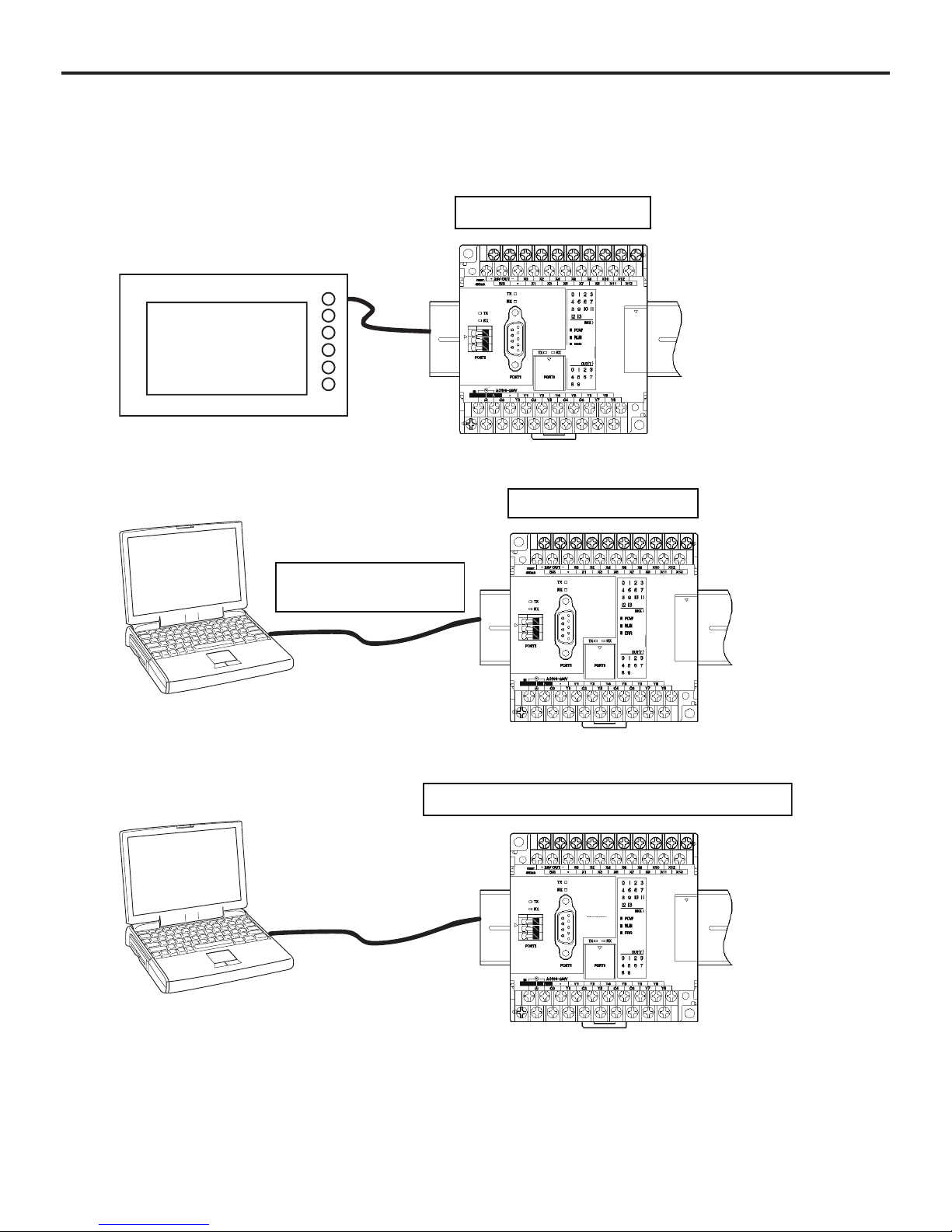
Engage the loader connector in a correct orientation, otherwise, an erratic operation might occur.
Before touching the PLC, discharge any static electricity that may have been collected on your body. To discharge it, touch
a grounded metallic object. Static electricity might cause erratic operation or failure.
Be sure to install the electrical wiring correctly and securely, observing the directions of the instruction manual and user’s
manual. Wrong or loose wiring might cause fire, accident or failure.
When disengaging the plug from the outlet, do not pull the cord, otherwiase, break of cable might cause fire or failure.
Do not attempt to change system configurations (such as installing or removing expansion block) while the power is ON,
otherwise, failure or erratic operation might occur.
Do not attempt to repair the module by yourself, but contact your Fuji Electric agent, otherwise, fire, accident or failure
might occur.
To clean the module, turn power off and wipe the module with a cloth moistened with warm water. Do not use thinner or
other organic solvents, as the module surface might become deformed or discolored.
Do not remodel or disassemble the product, otherwise, failure might occur.
Follow the regulations of industrial wastes when the device is to be discarded.
The products covered in this user’s manual have not been designed or manufactured for use in equipment or systems
which, in the event of failure, can lead to loss of human life.
Do not use the products covered in this user’s manual for special applications, such as power plant, radiation facilities,
railroad, space/flight equipments, lifeline facilities, or medical equipments, where a great effect on human life, body,
society, major property or rights may be anticipated and high degree of safety is required.
Be sure to provide protective measures when using the products covered in this manual in equipment which, in the event
of failure, can lead to loss of human life or other grade results.
External power supply (such as 24 V DC power supply) which is connected to DC I/O should be strongly isolated from AC
power supply, otherwise, accident or failure might occur. (Use of EN60950 conforming power supply is recommended.)
Do not use the peoducts covered in this user’s manual in a residential environment.
Caution

Revision
* The manual No. is printed at the bottom right of the cover of this manual.
Printed on * Manual No. Revision contents
Jan. 2017 FEH528 First edition
Apr. 2017 FEH528a NA0LA-RS3 was added.
Oct. 2017 FEH528b The safety precautions were revised.

Contents
Contents
Preface
Safety Precautions
Revision
Contents
General Section
Section G1 Communication Mode Introduction .......................................................................................... G-1
G1-1 Overview of Communication Modes ..........................................................................................................................G-1
G1-2 About Communication Port........................................................................................................................................G-6
Hardware Section
Section H1 Hardware Specications .......................................................................................................... H-1
H1-1 General Specications...............................................................................................................................................H-1
H1-2 Transmission Specications ......................................................................................................................................H-2
H1-3 Names and Functions................................................................................................................................................H-3
H1-4 External Dimensions..................................................................................................................................................H-6
H1-5 Communication Cable Wiring ....................................................................................................................................H-7
H1-5-1 RS-485 cable wiring ............................................................................................................................................H-7
H1-5-2 RS-232C cable wiring..........................................................................................................................................H-11
Software Section
Section S1 Communication Board/Unit Registration.................................................................................. S-1
Section S2 General Purpose Communication Mode Details...................................................................... S-3
S2-1 Overview ....................................................................................................................................................................S-3
S2-1-1 System denition setting .....................................................................................................................................S-3
S2-2 Connection Conguration ..........................................................................................................................................S-4
S2-3 Non-procedural FB Specications .............................................................................................................................S-5
S2-3-1 Communication specications.............................................................................................................................S-5
S2-3-2 FB format.............................................................................................................................................................S-6
S2-3-3 Description of FB parameters..............................................................................................................................S-8
S2-4 Initialization ................................................................................................................................................................S-10
S2-4-1 Initialization parameters ......................................................................................................................................S-10
S2-4-2 Initialization procedure ........................................................................................................................................S-12
S2-4-3 Open status list....................................................................................................................................................S-13
S2-5 Data Sending .............................................................................................................................................................S-14
S2-5-1 Data sending procedure......................................................................................................................................S-14
S2-5-2 Send status list....................................................................................................................................................S-14
S2-6 Data Receiving...........................................................................................................................................................S-15
S2-6-1 Data receiving procedure ....................................................................................................................................S-15
S2-6-2 Receive status list ...............................................................................................................................................S-15
Section S3 Loader Communication Mode Details...................................................................................... S-16
S3-1 Overview ....................................................................................................................................................................S-16
S3-1-1 Settings of system denition................................................................................................................................S-16
Section S4
CPU Link Communication (SPF mode) Details.............................................................................S-17
S4-1 Overview ....................................................................................................................................................................S-17
S4-1-1 Settings of system denition................................................................................................................................S-17
S4-1-2 Memory related to CPU link communication .......................................................................................................S-18

Contents
Section S5 Modbus RTU Master Communication Details.......................................................................... S-23
S5-1 Overview ....................................................................................................................................................................S-23
S5-1-1 Settings of system denition................................................................................................................................S-23
S5-2 Connection Conguration ..........................................................................................................................................S-24
S5-3 Communication Specications...................................................................................................................................S-25
S5-4 Function Code List.....................................................................................................................................................S-26
S5-5 FB Format ..................................................................................................................................................................S-27
S5-6 Description of FB Terminals .......................................................................................................................................S-29
S5-7 Error Status................................................................................................................................................................S-32
S5-7-1 Initialization status (O_STS)................................................................................................................................S-32
S5-7-2 Sending/receiving status (R_STS) ......................................................................................................................S-33
S5-8 Message Formats for Individual Function Codes.......................................................................................................S-34
Section S6 Memory Map............................................................................................................................ S-42

G-1
General Section
Section G1 Communication Mode Introduction
You can perform RS-232C/RS-485 communication between external devices by adding a communication board or unit to SPF.
Up to ve ports can be used (PORT 0 to 4). Port Nos. are dened according to the location of the SPF communication port.
For details, refer to “G1-2 About communication port”.
Select the communication mode in the parameter setting. The following four communication modes are available.
(1) General purpose communication
(2) Loader communication
(3) CPU link communication (SPF mode)
(4) Modbus RTU master communication
Note: The default parameter setting is “Loader communication”. Change the parameter setting for your purpose.
G1-1 Overview of Communication Modes
(1) General purpose communication
This communication mode allows data sending (or receiving) with external devices.
You need to create a communication program on the SPF side.
Enternal device
Data receive
Data send
Connect to communication board or unit

G-2
General Section
(2) Loader communication
This communication mode allows the connections shown below.
1) Connection to POD (MONITOUCH)
No application program for communication is required.
POD
Connect to CPU loader port
2) Connection to PC loader
USB connection
Dedicated cable (NA0H-CUV)
PC loader
Connect to CPU loader port
3) Connection to PC by creating a loader protocol communication program on the PC side
PC
Connect to CPU loader port, communication board or unit

G-3
General Section
* Notes on executing resource initialization of the CPU by the loader using Port 1 to Port 4
Be aware of the following notes when you use PORT 1 to 4 as Loader connection.
If you execute resource initialization using PORT 1 to 4, set the parameter setting to “Loader” and download the project le to
the PLC before resetting the PLC.
If you execute resource initialization using PORT 1 to 4, and then reset the PLC before downloading the project le to the PLC,
loader communication is disabled. To release the disabled status, set the parameter setting to “Loader” and download the project
using PORT 0.
If you execute resource initialization using PORT 0, no need to worry about the notes above.
[Case where loader communication is disabled]
When you connect the loader to PORT1 to 4, and then execute “Resource initialization” -> “Reset”.
[Case where loader communication is not disabled]
When you connect the loader to PORT1 to 4, execute “Resource initialization”, set parameter setting to “Loader”, download the
project, and then reset the PLC.

G-4
General Section
(3) CPU link communication (SPF mode)
This communication mode enables data sharing between multiple CPUs (N-to-N communication). Data communication can be
performed simply by setting the station No. and area in the parameter setting. Only RS-485 is supported.
* CPU link communication specications of SPF are different from those of SPB/SPE. Therefore, the CPU link of SPF series
cannot be combined with that of SPB/SPE series
Connect to communication board or unit (RS-485)
CPU 2 data
CPU 1 data
CPU 0 data
<For your information>
The link communication data refresh cycle is 165ms or less for the following conguration.
Scan time : 5ms or less, Maximum conguration (16 stations, data size setting is 32W for each station)

G-5
General Section
(4) Modbus RTU master communication
SPF acts as a Modbus RTU master, and communicates with multiple slaves.
You need to create a communication program using Modbus FB on the SPF side.
Modbus RTU slave device Modbus RTU slave device Modbus RTU slave device
Modbus RTU master
Connect to communication board or unit (RS-485)

G-6
General Section
G1-2 About Communication Port
The table below shows the specications of each communication port.
Port location CPU built-in
loader port
Communication expansion
board
(Attach on the front of CPU)
Communication expansion
unit
(Attach on the left of CPU)
Port number PORT0 PORT1 PORT2 PORT3 PORT4
Communication
mode
General purpose
communication Not supported Supported Supported Supported Supported
Loader communication Supported Supported Supported Supported Supported
CPU Link communication
(SPF mode)
(Only one port from PORT
1 to 4)
Not supported Supported Supported Supported Supported
Modbus RTU master
communication Not supported Supported Supported Supported Supported
Communication
Parameter
Baud rate (bps) 38400 1200/2400/4800/9600/19200/38400/57600/115200
Data bit 8 7/8
Parity Even None/Odd/Even
Stop bit 1 1/2
Physical
interface
NA3LA-RS1
(Communication board) –RS-232C RS-485 – –
NA0LA-RS5
(Communication unit) –––RS-485 RS-485
NA0LA-RS3
(Communication unit) –––RS-232C RS-232C
RS-232C control signal (RTS, CTS) Not supported Supported Supported Not supported Not supported
Number of connectable stations 1 (RS-232C) 1 (RS-232C)
Max. 16 (RS-485) (including self station)

H-1
Hardware Section
Section H1 Hardware Specications
H1-1 General Specications
The table below shows the communication board/unit specications. For the general specications, refer to the user’s manual “SPF
Hardware (FEH526).”
Item Specication
Internal power consumption
NA3LA-RS1: 5V DC, 55mA or less (supplied from basic unit)
NA0LA-RS5: 5V DC, 95mA or less (supplied from basic unit)
NA0LA-RS3: 5V DC, 18mA or less (supplied from basic unit)
Mass
NA3LA-RS1: Approx. 30g
NA0LA-RS5: Approx. 50g
NA0LA-RS3: Approx. 80g
External dimensions Refer to “H1-4 External Dimensions”.

H-2
Hardware Section
H1-2 Transmission Specications
Item Specication
Interface RS-232C RS-485
Synchronization method Start-stop synchronous transmission
Baud rate (bps) 1200/2400/4800/9600/19200/38400/57600/115200
Transmission distance 15m or less 1km or less (at 19200bps or less)
Number of connectable units 1:1 1:15 (Max)
Connection method PORT 0: mini DIN-4 pin (female)
PORT 1 to 4: D-sub9 pin (female) 3-pole European-style terminal block
Transmission code Binary (without code conversion), ASCII (with code conversion) or EBCDIC (with code
conversion)
Error control
Hardware Vertical parity (parity bit), framing error, overrun error
Software Horizontal parity (BCC)
Bit send sequence From the lower-order bit (from LSB to MSB)
Data length which can be sent
or received at one time
(viewed from the PLC)
512 bytes max. (Depending on the mode)
Start code None / 1 to 5 bytes
End code 1 to 5 bytes
Character conguration
Start bit: 1 (xed)
Data bit: 7/8
Parity bit: None/Odd/Even
Stop bit: 1/2

H-3
Hardware Section
H1-3 Names and Functions
(1) Names
NA3LA-RS1 (Communication expansion board: RS-232C × 1ch, RS-485 × 1ch)
1) RS-232C transmission status LED
2) RS-232C connector
3) RS-485 transmission status LED
4) RS-485 terminal block
5) RS-485 terminating resistor switch
* Inside the surface cover
PORT2
TX
RX
PORT1
TX
RX
NA0LA-RS5 (Communication expansion unit: RS-485 × 2ch)
NA0LA-RS5
PORT3 (RS485)PORT4 (RS485)
TX
RX
T N
TX
RX
T N
G
-
+
G
+
-
3) RS-485 transmission status LED
4) RS-485 terminal block
5) RS-485 terminating resistor switch
NA0LA-RS3 (Communication expansion unit: RS-232C × 2ch)
NA0LA-RS3
PORT3 (RS232)
RX
TX
PORT4 (RS232)
RX
TX
2) RS-232C connector 1) RS-232C transmission status LED

H-4
Hardware Section
(2) Functions
1) RS-232C transmission status LED
These LEDs indicate the RS-232C transmission status.
Symbol Color Lighting condition
TX Red ON while sending data
RX Green ON while receiving data
Pin No. Signal
name
Signal direction
SPF 1External device Description
1– – Not connected
2TXD gSend data
3RXD fReceive data
4– – Not connected
5SG – Signal ground
6– – Not connected
7CTS fClear to send (valid for PORT 1, 2)
8RTS gRequest to send (valid for PORT 1, 2)
9– – Not connected
2) RS-232C connector
D-sub9 pin female connector. The screws on both ends of the connector are inch type screws.
Note that the pin assignment is opposite to that of normal RS-232C.
Inch screw
5
9
6
1

H-5
Hardware Section
Symbol Color Lighting condition
TX Red ON while sending data
RX Green ON while receiving data
Signal name Description
+ (D+) RS-485 transmission+
- (D-) RS-485 transmission-
G (SG) Signal ground
3) RS-485 transmission status LED
These LEDs indicate the RS-485 transmission status.
4) RS-485 terminal block
+
G
5) RS-485 terminating resistor switch
Set both switches to ON when SPF is located at the end of RS-485.
Otherwise, set both switches to OFF.
12
ON
TN

H-6
Hardware Section
H1-4 External Dimensions
NA0LA-RS5, NA0LA-RS3
25
90
90
73
25
21
3.8
2 - 4.5
7.5
Unit: mm
* NA3LA-RS1 (front board) is stored inside the CPU.

H-7
Hardware Section
H1-5 Communication Cable Wiring
H1-5-1 RS-485 cable wiring
RS-485 provides connection for multiple stations. Its wiring distance must conform to the restriction specied in the EIA standard.
For hardware wiring, observe the principle that connection distance should be as short as possible and the station should be far
away from high noise sources.
RS-485 communication quality is affected and operation might be seriously interfered with if the problems, such as high baud
rate, long connection distance, high signal attenuation, multiple stations, bad grounding, high noise, terminating impedance
mapping, and topology, are not solved appropriately.
Read the notes of hardware wiring for RS485 network at the end of this section carefully.
<Limits on the number of stations>
The maximum number of stations for RS-485 interface is 16 (including self station).
<Limit on distance>
The following diagram shows the relationship between the baud rate and transmission distance of RS-485 standard interface.
Use within the shaded area.
3040
1200
300
30
12
3
40 100K 1M 10M
Transmission distance (m)
Baud rate (bps)
Other manuals for MICREX-SX series
4
Table of contents