Tool-Temp TT-13'502 E User manual

Manual TT-13’502 E - 1 -
THE HEATING AND COOLING UNIT
HAS TO BE TRANSPORTED IN AN
UPRIGHT POSITION AND NEVER ON
THE SIDE.
SHOULD THE UNIT BE LAID DOWN TO
THE SIDE DURING TRANSPORT, IT
WILL SUFFER IRREPARABLES
DAMAGES.

Manual TT-13’502 E - 2 -
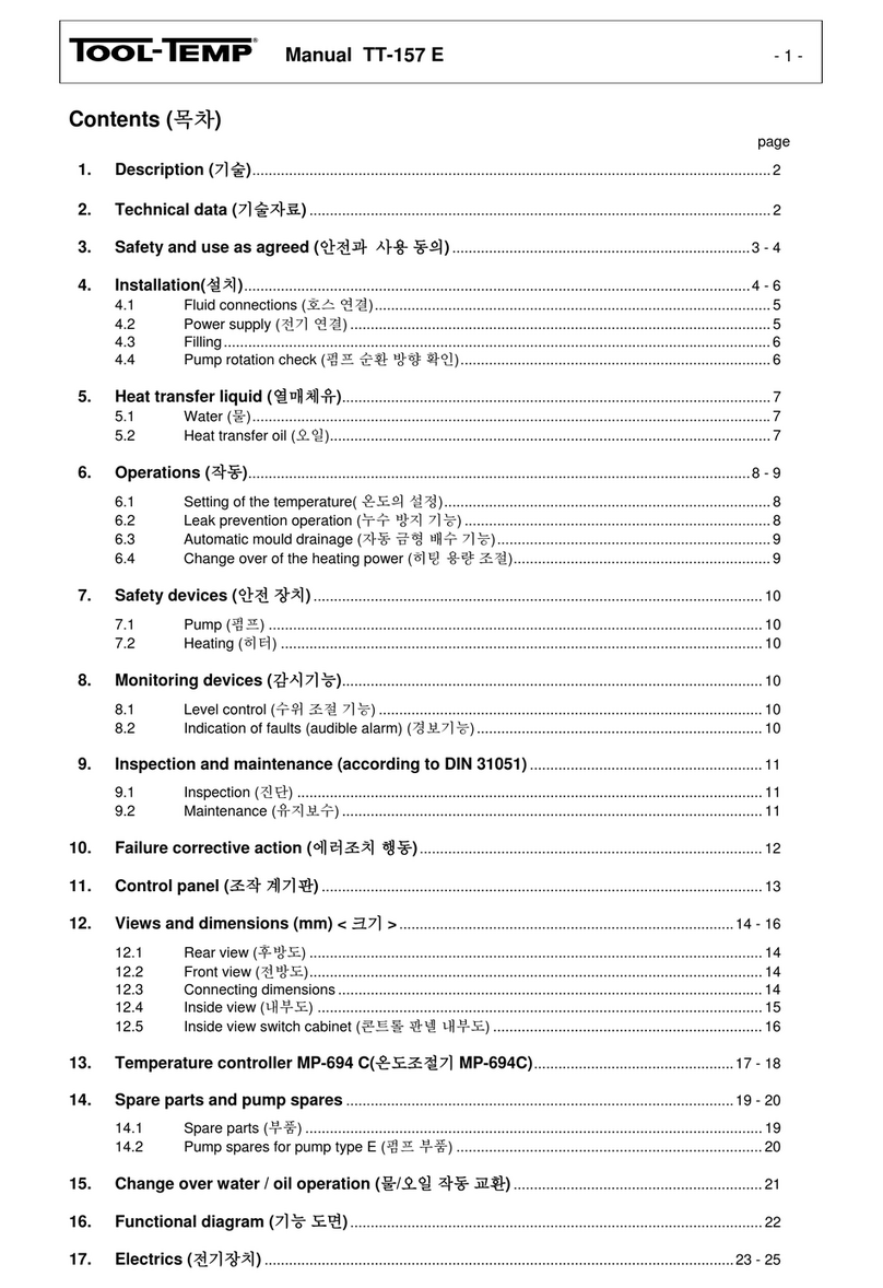
Contents
page
1. Description ..........................................................................................................................................3
2. Technical data.....................................................................................................................................3
3. Safety and use as agreed.................................................................................................................4
4. Installation .....................................................................................................................................5 - 7
4.1 Configuration..........................................................................................................................5
4.2 Water connections..................................................................................................................5
4.3 Power supply..........................................................................................................................6
4.4 Filling......................................................................................................................................6
4.5 Pump rotation check...............................................................................................................7
5. Operation .............................................................................................................................................7
5.1 Setting of temperature............................................................................................................7
5.2 External control ......................................................................................................................7
6. Safety devices.....................................................................................................................................8
6.1 Pump......................................................................................................................................8
6.2 Compressor (circuit 1)............................................................................................................8
6.3 Fan (circuit 1) .........................................................................................................................8
6.4 Heating...................................................................................................................................8
7. Monitoring devices............................................................................................................................9
7.1 Level control...........................................................................................................................9
7.2 Anti-freeze (circuit 1)..............................................................................................................9
7.3 Indications of defaults (audible alarm)....................................................................................9
7.4 Pressure control (circuit 1)......................................................................................................9
8. Inspections and maintenance (according to DIN 31051).......................................................10
8.1 Inspection.............................................................................................................................10
8.2 Maintenance ........................................................................................................................10
9. Failure corrective action .........................................................................................................11 - 13
10. Control panel TT-13’502 E .............................................................................................................14
11. Views and dimensions (in mm).............................................................................................15 - 17
11.1Front view.............................................................................................................................15
11.2 Rear view .............................................................................................................................15
11.3 Dimensions...........................................................................................................................15
11.4 Inside view............................................................................................................................16
11.5 Inside view of control panel .................................................................................................17
12. Temperature controller MP-888.............................................................................................18 - 23
12.1Predefined setups ................................................................................................................19
12.2 Programming MP-888: Heating- and cooling unit TT-13'502 E without flow control......20 - 23
13. Spare parts list...........................................................................................................................24 - 25
14. Datasheet time-lag relay ...............................................................................................................26
15. Electrics ......................................................................................................................................27 - 30

Manual TT-13’502 E - 3 -
1. Description
The heating- and cooling unit TT-13’502 E is operating with antipollution and CFC-free refrigerant agent
The unit has two independent water circuits with two sealless pumps and two stainless steel water tank of
each 25 litres content. Additionally, the unit is equipped with 2 x 6 kW heating capacity. Circuit 2 can only
be cooled when circuit 1 is operating.
The unit corresponds to the harmonized EU norms as EN 292 / EN 60204 as well as to the relevant EU
directives (see EU conformity declaration) and it is provided with the CE sign.
This manual is valid only for this model.
serial equipment:
- 2 self-optimizing temperature controllers with digital display of the set and actual temperature.
Display in 1/10-° range. Switchable from °C to °F.
- horn for default indication
- automatic level control – with pre-warning by too low water level
- automatic or manual water refill
- mechanical safety thermostat and electronic temperature limiter installed in the controller
- with main switch, automatic cutout, transformer and motor protection switch
- with castors
2. Technical data
temperature range
of medium (water)
Circuit 1 for temperatures from +10°C to +40°C
Circuit 2for temperatures from +10°C to +90°C
ambient temperature
min. +2°C / max. +45°C,
use anti-freeze below +2°C in order to protect the heating and cooling unit from
freezing and becoming defective
temperature control
self-optimising microprocessor controller MP-888
refrigerant agent
R-134a
cooling capacity
8 kW for both circuits
heating capacity
approx. 2 x 6 kW
pump capacity
connected load 0,75 kW
pressure mode max. 4,5 bar / max. 75 l/min.
compressor
hermetically sealed
Condenser
air-cooled, air inlet located at the front of the unit, blow out located at the side and
at the rear of the unit.
max.power consumption
approx.. 15 kW
filling amount
approx. 2 x 25 litres
connections
to / from mould R 3/4“ female thread (both circuits)
automatic water refill R 3/8“ female thread
drainage R 3/8“ female thread
dimensions in mm
(LxWxH) incl. castors
Length: 980 mm
Width: 660 mm
Height: 1’300 mm
weight
empty approx. 220 kg
category of protection
IP-44
Electric
in separate switch cabinet, easily accessible from the front
colour
silver grey RAL 7001
noise level (dBA)
66 (distance 3 m)

Manual TT-13’502 E - 4 -
3. Safety and use as agreed
The heating and cooling unit must not be used for other than the described purpose and within the fixed
values for temperature and voltage. Any other use whithout the agreement of the manufacturer is strictly
forbidden. The use of others than the prescribed water (see point 4.4) and/or the use of others than the
admitted spare parts can lead to dangerous operating states and is strictly forbidden. When the unit’s con-
struction state is changed the operating permission and the conformity declaration become unvalid.
Important information in this manual is marked as follows:
remark:
helpful information
CAUTION:
RISKS WHICH CAN LEAD TO MATERIAL DAMAGE
DANGER:
RISKS WHICH CAN LEAD TO HUMAN INJURY
The heating and cooling unit is equipped with the following pictographs (according to DIN 4844) to mark
the remaining dangers (according to EN 1050):
DANGER VOLTAGE
DANGER
-The heating and cooling unit must not be used in hazardous location.
-The heating and cooling unit must not be used in the open air (category of protection IP-44).
-The heating and cooling unit must not be transported in a horizontal position.
Should the unit be laid down to its side during transportation, it will suffer irreparables damages.
-Water is the only permitted medium for the use in the heating and cooling unit (see point 4.4).

Manual TT-13’502 E - 5 -
4. Installation
Before starting the unit the external connections of the hydraulics and of the electric have to be mounted.
CAUTION:
STARTING THE UNIT WITHOUT THE PRESCRIBED
CONNECTIONS CAN DAMAGE IT.
The starting of the unit has to be done in the order of this chapter.
After the proper starting the unit is ready to use.
4.1 Configuration
air inlet: at the front of the unit
air outlet: at the side and at the rear of the unit
ambient temperature: +2°C to +45°C use anti-freeze below +2°C in order to protect the heating
and cooling unit from freezing and becoming defective
CAUTION:
-
AIR INLET AND OUTLET MUST BE OPEN AND ACCESSIBLE IN
ORDER TO GUARANTEE A SUFFICIENT AIR CIRCULATION
SHOULD THE UNIT BE LAID DOWN TO ITS SIDE DURING
TRANSPORTATION, IT WILL SUFFER IRREPARABLE
DAMAGES
CAUTION :
-THE UNIT CAN ONLY BE PLACED IN SUITABLE ROOMS AND
ON PLAIN FLOOR.
-THE ROOM HEIGHT MUST BE AT LEAST 3 M.
-THE UNIT IS NOT JET-PROOFED AND NOT ALLOWED TO BE
OPERATED IN HAZARDOUS LOCATION.
-THE UNIT IS ONLY DESIGNED FOR INSIDE USE AND
CANNOT BE OPERATED OUTSIDE.
4.2 Water connections
We recommend that transparent reinforced hoses should be used so that the cleaness of the water can be
checked. Longer hoses must be insulated.
to- / from mould
R 3/4“ female thread
automatic water refill
R 3/8“ female thread
drainage
R 3/8“ female thread
water filter and automatic water refill
R 3/8“ female thread

Manual TT-13’502 E - 6 -
4.3 Power supply
Main voltage and frequency according to the serial plate.
Pay attention to the local regulations during installation of unit.
CAUTION:
THE CONNECTION TO THE POWER SUPPLY HAS TO BE DONE
BY A QUALIFIED ELECTRICIAN.
Colours of cables:
phases
black / black / black
L1 / L2 / L3
earth
yellow / green
PE
max power consumption: approx. 15 kW
DANGER:
CONNECT THE POWER SUPPLY FIRST WHEN THE HOSES
HAVE BEEN CONNECTED.
4.4 Filling
Manual filling:
Content of approx. 2 x 25 Litres. The manual filling is on the top of the unit (see page 15).
We recommend the use of normal tap water.
CAUTION:
DO NOT USE DISTILLED, DEIONISED OR RAIN WATER.
WATER CONTAINING CHLORID ADDITIVES DESTROYS ON
LONG TERMS THE STRUCTURE OF STAINLESS STEEL. DO
NOT ADD CHLORID TO THE WATER!
Automatic filling
The unit is equipped with an automatic water refill as standard. After switching on the unit the tank will au-
tomatically be filled to the correct level.
Remark:
We recommend that a stop valve is fitted at the water inlet.
This valve should be closed after filling of the tank so that uncon-
trolled refill can be avoided in case of a malfunction.
This unit is not designed to work below +2°C ambient temperature.
If the unit is installed in a production hall with low ambient temperatures, we recommend to add anti-
freeze. The percentage of anti-freeze depends on the lowest ambient temperature.

Manual TT-13’502 E - 7 -
4.5 Pump rotation check
As soon as the unit has been connected to the main supply, hoses connections have been made and the
water has been filled, the sense of rotation of the pump must be checked. This can be done by shortly
switching the unit on. The sense of rotation must be clockwise as shown by the arrow.
In case of anti-clockwise rotation you need to invert two phases on the electrical connection (on the plug or
main supply). This must be done by a qualified electrician only.
Info:
Using a sheet of paper allow if the sense of rotation of the fan is
correct. The sheet of paper must be placed at the rear side of the
unit and should stick to the condenser. Please remove it after test.
If the fan is rotating in the correct direction, the pump is rotating
correctly as well.
The fan runs only if a certain pressure of the refrigerant agent is reached. By too cold air, the fan gets
switched off thanks to a pressure switch (pressostat F42).
5. Operation
For the operating and display elements on the temperature controler see chapter 12 "temperature
controller MP-888."
5.1 Setting of temperature
Temperature range circuit 1: +10°C to +40°C
Temperature range circuit 2: +10°C to +90°C
The required temperature on the temperature controller can be adjusted by pressing the flashes
CAUTION!
PAY ATTENTION TO THE MAXIMUM ALLOWED
TEMPERATURES FOR THE USED HEAT TRANSFER
LIQUID AND HOSES.
The operator can choose the more convenient settings: degree Celsius or degree Fahrenheit.
When the controller gets started, the temperature unit is shown for a short moment.
See instructions „Programming: temperature controller MP-888 for details about function and setting of the
controller (see chapter 12).
5.2 External control
external control of 0-10 V / 4-20 mA is possible. No other interfaces can be used.

Manual TT-13’502 E - 8 -
6. Safety devices
The resetting of the thermal relay can be done by pressing the resetting button on the thermal relay of the
pump motor contactor.
6.1 Pump
The pump motor is protected by a thermal relay – control lamp .
6.2 Compressor (circuit 1)
The compressor is protected by a thermal relay – control lamp .
Info:
The control of the compressor is programmed in a way that a short
on/off is avoided (time-lag of approx. 30 sec.). This guarantees a
long life of the compressor.
6.3 Fan (circuit 1)
The fan is protected by a thermal relay – control lamp .
To guarantee an optimal function of the refrigerating circuit at low ambient temperature, a pressure switch
(ON-/ OFF switch) controls the starting point of the fan.
6.4 Heating
The safety thermostat is set to the maximum allowed temperature. If this temperature is exceeded the red
lamp is lit and the safety thermostat switches the whole unit off.
As soon as the medium temperature falls below the set point the unit automatically switches on again.
Circuit 1:
Circuit 2:
Above +45 °C the whole unit will be
switched off
Within that temperature range the cooling
compressor switches ON/OFF normally
50 °C
40 °C
30 °C
20 °C
10 °C
8 °C
Above +100 °C the whole unit will be
switched off
Within that temperature range the cooling
compressor switches ON/OFF normally
90 °C
80 °C
70 °C
50 °C
40 °C
30°C
20°C
10°C

Manual TT-13’502 E - 9 -
7. Monitoring devices
7.1 Level control
The unit is fitted with two level controls :
yellow lamp on the left is lit: Pre-warning – there is too little water in the tank.
The unit is still working and the horn is activated. Water will
automatically be refilled (see point 4.4). Please also see page 6 –
stop-valve on water inlet.
yellow lamp on the right is lit: The unit stops and the alarm is activated because the level has fallen
below the minimum. The alarm can be switched off by the horn switch
7.2 Anti-freeze (circuit 1)
If the water temperature of the standard unit falls below +8°C the indication lamp is lit and the frost
protection thermostat switches the cooling (compressor) off. It prevents the unit from damages.
7.3Indications of defaults (audible alarm)
During normal operation the horn should be switched on. Any default will then be indicated acoustically.
7.4 Pressure control (circuit 1)
Each unit is equipped with a high- and a low-pressure pressostat with reset button.
-If the ambient temperature exceeds +45 °C or the condenser is not clean, the unit switches off and the
high-pressure lamp HP on the right is lit. (After the failure corrective action the reset button has to be
pushed).
-If not enough refrigerating agent is in the system or the unit is frozen, the low pressure lamp
LP on the left is lit. (After the failure corrective action the reset button has to be pushed).

Manual TT-13’502 E - 10 -
8. Inspection and maintenance (according to DIN 31051)
Inspection and maintenance has to be carried out by instructed staff.
Please contact the manufacturer or your supplier for eventually necessary steps going beyond.
8.1 Inspection
Before starting the heating and cooling unit the following has to be checked:
- condition and tightness of the water connections
- electrical connections
8.2 Maintenance
CAUTION:
DISCONNECT THE UNIT FROM THE POWER SUPPLY
PRIOR TO ANY MANIPULATION ON THE UNIT.
The heating and cooling unit needs periodical checking and cleaning.
Disconnect the unit from the power supply prior to carrying out any work on the unit.
The following service is recommended to grant problem-free operation:
clean fan impeller of pump motor by using compressed air
every 6 months
clean condenser with a soft brush or by using compressed air
every 6 months
CAUTION:
DO NOT USE A METAL BRUSH FOR CLEANING THE
CONDENSER.
These intervals are for standard operation.
For extreme operation these intervals must be shortened accordingly.
Established defects must be repaired.
To guarantee safety the unit must be repaired with original spare parts only.

Manual TT-13’502 E -11 -
9. Failure corrective action
symptom possible cause correction
Green ON/OFF switch and all
lamps are not lit, unit does not work -fuse defective
-possibly transformer or switch
defective
-open the front door
-replace the fuse 5 x 20 mm 1 A
-replace the defective parts
yellow lamp is lit „level control“
left lamp is lit
unit is working
horn sounds :
and can be switch off by the on/off
switch .
right lamp is lit,
unit is not working
horn sounds: - - - - - - - - - - and
can be switch off by the on/off
switch
prewarning – less medium in the
tank, automatic water refill is
defective or not connected
too little water in the tank, automatic
water refill is defective or not
connected.
connect automatic water refill and
open the valve or fill manually
check float, solenoid valve and elec-
trical wiring.
water filter probably needs to be
cleaned.
red lamp „thermal relay pump“
is lit
horn sounds: - - - - - - - - - -
and can be switch off by the on/off
switch
-pump thermal relay has responded
-phase failure (thermal relay)
-pump defective
-pump overheated
-open the front door
-press the blue button on pump
thermal relay
-check electrical wiring
-repair or replace pump
Circuit 1:
red lamp „compressor thermal relay”
is lit -compressor thermal relay has
responded
-phase failure
-motor winding too hot
-open the front door
-press the blue button on
compressor thermal relay
-check electrical wiring
Circuit 1:
red lamp “fan thermal relay”
is lit -fan thermal relay has responded
-phase failure
-open the front door
-press the blue button on fan
thermal relay
-check electrical wiring

Manual TT-13’502 E -12 -
symptom possible cause correction
compressor and pump are not
working; no fault is indicated internal overload relay of the
compressor (thermostat Pilotherm)
has responded.
switch the unit off immediately and
get it checked by a refrigeration
engineer
Circuit 1:
red lamp "LP-HP" is lit Low or high pressure pressostat has
responded If the problem is solved, please
press the reset button on the LP or
HP pressostat
left lamp LP is lit Low pressure
-no water circulation
-too little freon in the system
-expansion valve defective
-running temperature too low
-ambient temperature too low
-water frozen – let the unit thaw
(approx. 1 day), check pump and
circulation
-let the unit be checked by a
refrigeration engineer
-check controller
-check anti-freeze thermostat
- re-site the unit, eventually
contact the supplier.
-add anti-freeze
Circuit 1:
right lamp HP is lit High pressure
-water temperature above +45°C
-ambient temperature too high
-condenser soiled
-fan defective
-fan rotation not correct
-wait until the temperature has
dropped, check capacity of unit
-check fresh air inlet
-clean condenser with soft brush,
do not use metal brush
-repair or exchange fan
-invert 2 phases
(check pump direction,
see point 4.5)
If the problem is solved, please
press the reset button on the LP or
HP pressostat
red lamp „water safety thermostat
is lit -water temperature above +45°C
-ambient temperature above +45°C
-cooling capacity too low – try to
find the cause
-wait until the water temperature
has dropped
- re-site the unit, eventually
contact the supplier.
red lamp „anti-freeze“
is lit As soon as the temperature on the
standard version drops below +8°C
the anti-freeze thermostat responds
in order to protect the unit from
becoming frozen and defective.
-temperature controller defective
-ambient temperature too low
-wrong adjustment on anti-freeze
thermostat
wait until the unit has reached a
higher temperature
do not set the controller below
+10°C
-exchange the controller
-contact the supplier
-check the adjustment on the anti-
freeze thermostat
set temperature cannot be reached - heating not switched on
-controller defective
- heating element defective
-switch on the heating
-exchange the controller
-contact the supplier

Manual TT-13’502 E -13 -
symptom possible cause correction
Lamp „cooling“ is lit no default
simply shows that the cooling is
active.
unit is not cooling anymore but the
compressor is running -loss of refrigerant agent
-unit is working in the fringe range
of the cooling capacity
contact the supplier
CAUTION:
DISCONNECT THE UNIT FROM THE POWER SUPPLY
PRIOR TO ANY MANIPULATION ON THE UNIT.

Manual TT-13’502 E -14 -
10. Control panel TT-13’502 E
9. Control lamp
overload relay
compressor
10.Control lamp overload
relay fan
1. ON/OFF switch unit
8. Indication lamp (green):
cooling active
11.Lamp pressure control:
LP: low pressure
5. Control lamp
overload relay pump
Circuit 1
7. Control lamp
water temperature in
the tank too low
4. Level control lamp:
dropping below the
minimum level
-Unit switches off
13.ON/OFF switch
horn: ON means that in
case of a defect the
horn will be activated
3. Level control lamp: pre-
warning, not enough
liquid in the unit
2. ON/OFF switch
heating
see„Temperature
controller MP-888 /
programming“
Circuit 2
6. Control lamp
water temperature in
the tank too high
1
2
3
4
5
6
8
1
2
3
4
5
6
8
7
11
12
9
10
13
13
12.Lamp pressure control:
HP: high pressure

Manual TT-13‘502 E -15 -
11. Views and dimensions (in mm)
11.1 Front view
Main switch
Air outlet
Circuit 1:
From mould R 3/4“
female thread
Circuit 2:
Drainage R 3/8“
female thread
Autom. refill
R 3/8“ female
thread
Air outlet
Circuit 1:
To mould R 3/4“
female thread
Control panel
11.2 Rear view
11.3 Dimensions
660
980
1180
1300
120
Manual fill
Overlfow
Air inlet
Air outlet
Circuit 1:
Drainage R 3/8“
female thread
Circuit 2:
From mould R 3/4“
female thread
Circuit 2:
To mould R 3/4“
female thread

Manual TT-13‘502 E -16 -
11.4 Inside view
Compressor
Expansion valve
Electrical cabinet
Pump with motor
(Circuit 2)
Pressostat LP/HP
Float with
microswitch
(circuit 2)
Drier
Solenoid valve
freon
Fan with motor
Freon collector
Tank
(circuit 2)
Condenser
Sight glass
freon indicator
Plate heat exchanger
autom. refill
Pressostat fan
Pump with motor
(Circuit 1)
Float with
micorswitch
(Circuit 1)
Tank
(Circuit 1)

Manual TT-13'502 E -17 -
11.5 Inside view of control panel
temperature controller
MP-888 (N1, N2)
horn (H15)
thermal relay
pump (F1, F2)
thermal relay
compressor (F3)
auxiliary relay start-delayed
(K23) with RR 900
contactor pump motor (K1, K2)
max. and min.
thermostat
(F13, F14, F42)
main switch(Q1)
contactor
compressor (K5)
contactor heating
(K3, K4)
control fuse
primary voltage (F7)
control fuse
secondary volt. (F8)
transformer (T1)
thermal relay
fan (F4)
automatic cut off
(F22, F20)
contactor fan (K6)
auxiliary relay
(K25-/2/3/4/5)

Manual TT-13'502 E -18 -
12.Temperature controller MP-888
cooling switched on
heating switched on
sensor failure
controller is triggered from
external source with a signal of
0-10 V - or 4-20 mA
electronic safety
thermostat
automatic temperature
monitoring / upper and
lower limit contact
programming key:
press the button for
3 sec.
Program steps:
P01 maximum temperature
0-400 °C
(set value +50 °C)
P02 temperature monitoring
limit +/- 20 °C
(set value +/- 5 °C)
set point
actual value
connections 26 - 28
for external analogue set point
0-10 V oder 4-20 mA
heating
cooling
possible supply voltages –
factory adjusted
current supply
temperature monitoring
(extreme value)
possible heat sensor –
factory adjusted
program version
of the controller
heat sensor connection
set point:
adjustment of the
required temperature
flow control – actual flow value
flow control finger tip (reset)
flow control –
minimum flow
flow control
connections 29 + 30
for external analouge actual value
0-10 V

Manual TT-13'502 E -19 -
12.1 Predefined setups
Temperature controller circuit 1 (10 – 40°C):
The temperature controller must be set on the program P12.
Temperature controller circuit 2 (10 – 90°C):
The temperature controller must be set on the program P41 and the following parameters has to be changed.
- P1: Set max. temperature to 90°C
-P21: Set the temperature sensor to Pt 100 2-Draht
The controller finally indicates the program P100 (specialprogramming).
Table of contents
Other Tool-Temp Industrial Equipment manuals
Popular Industrial Equipment manuals by other brands
ABB
ABB HT613304 Operation manual
ABB
ABB HT572706 Operation manual
MUSASHI ENGINEERING
MUSASHI ENGINEERING SHOTMASTER QX Series SHOTMASTER SX Series instruction manual
Graco
Graco ProBell instructions
CHART
CHART Trifecta XPro Series product manual
Tractel Group
Tractel Group Dynasafe HF 32 Operating and maintenance manual

