ProBellSystemInformation
ProBell ProBell
ProBellSystem System
SystemInformation Information
Information
Thismanualprovidesinstructionsonhowtocomplete
theassemblyofacart-mountedProBellRotary
ApplicatorSystem,whichincludesthefollowing
components.
•TheRotary Rotary
RotaryApplicator Applicator
Applicatorcomesinvariousmodels.
SeetheModelslistforapplicatorsthatareavailable
withasystem.Manuals334452or334626arethe
mainsourceofsysteminformation.Theyinclude
installationandoperationinstructionsaswellas
maintenanceandrepairinformation.
•TheSystem System
SystemLogic Logic
LogicController Controller
Controllercontrolsandmonitors
therotaryapplicatorsystemfunctionsthrough
theuserinterfaceorthroughcommunicationwith
aPLC.ASystemLogicControllerisrequiredif
yoursystemincludesaSpeedControlleroranAir
Controller.MounttheSystemLogicControllerin
thenon-hazardousarea.Manual3A3955contains
allinformationneededtounderstandthesetupand
operationofthesystemviatheuserinterface.It
alsocontainsdetailedtroubleshootingandevent
codeinformation.
•TheSpeed Speed
SpeedController Controller
Controllerdirectstheturbineairand
brakeairtotheapplicator.Thecontrollerusesa
beropticsignalfromtheProBellapplicatorto
providepreciseclosed-loopcontrolofthebellcup
rotationspeed.TheSpeedControllermustbe
mountedinthenon-hazardousarea,ascloseto
theapplicatoraspossibletominimizepressure
lossintheairlines.Manual3A3953contains
specicinstallation,troubleshooting,repair,and
partsforthiscomponent.
•TheAir Air
AirController Controller
Controllerelectronicallycontrolstheinner
andoutershapingair.Italsoprovidesairactivation
signalsforthepaint,dump,andsolvent(cupwash)
valvesintheapplicator.MounttheAirControllerin
thenon-hazardousarea,asclosetotheapplicator
aspossibletominimizepressurelossinthe
airlines.SeeManual3A3954forinstallation
instructionsandfeaturesofeachaircontroller,
specicinstallation,troubleshooting,repair,and
partsforthiscomponent.
•TheElectrostatic Electrostatic
ElectrostaticController Controller
Controllersendspowertothe
applicatorpowersupply,whichincreasesthe
voltagetothelevelsetatthecontroller.Itmust
bemountedinthenon-hazardousarea.See
ProBellElectrostaticControllermanual3A3657
forallinformationneededtounderstandthisuser
interface.
•TheTwenty Twenty
TwentyMeter Meter
Meter(65 (65
(65ft) ft)
ft)Hose Hose
HoseBundle Bundle
BundleKit Kit
Kitincludes
9airlines,aberopticcable,powersupplycable,
groundingcable,and3uidlines(purchaseuid
linesseparatelyforwaterbornesystems).
•TheCGM CGM
CGM(CommunicationGatewayModule)
providesacontrollinkbetweentheProBellsystem
andaselectedeldbus.Thislinkageprovides
themeansforremotemonitoringandcontrolby
externalautomationsystems.TheProBellsystem
supportsModbusTCP,EtherNet/IP,DeviceNet,
andPROFINET.Onegatewaycansupporttwo
ProBells.SystemrequiresaProBellsystemCGM
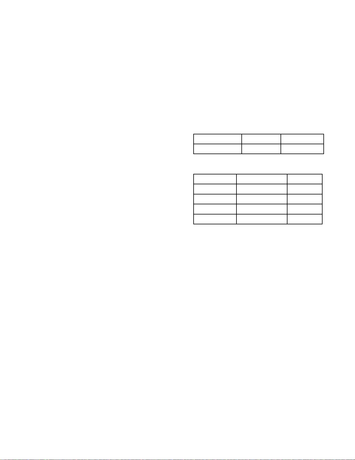
installationkitandgateway.Seethefollowing
tables.
Table Table
Table1 1
1ProBell ProBell
ProBellSystem System
SystemCGM CGM
CGMInstallation Installation
InstallationKit Kit
Kit
PartNumberFieldBusManual
24Z574All3A4384
Table Table
Table2 2
2Communication Communication
CommunicationGateway Gateway
GatewayModule Module
Module
PartNumberFieldBusManual
CGMDN0DeviceNet312864
DGMEP0EtherNet/IP312864
DGMPN0PROFINET312864
24W462ModbusTCP334183
Electrical Electrical
ElectricalInputs Inputs
Inputsand and
andOutputs Outputs
Outputs
ThefollowingdiscreteI/Oconnectionscanbeused
todrivethesystemremotely.
Speed Speed
SpeedController Controller
Controller
•Systemstatusoutput
•OptionalInterlockinput
Electronic Electronic
ElectronicAir Air
AirController Controller
Controller
•PaintTriggerInput
•OptionalInterlockInput
Electrostatic Electrostatic
ElectrostaticController Controller
Controller
•Safe-to-MoveOutput
•ErrorOutput
•ActualSprayingCurrentOutput
•ActualSprayingVoltageOutput
•ElectrostaticsDischargedOutput
•SAFEPOSITIONInterlockInput
•24VDCInterlockInput
•SystemInterlock
•ElectrostaticEnableInput
3A4232D9