manuals.online logo
Brands
  1. Home
  2. •
  3. Brands
  4. •
  5. SMC Networks
  6. •
  7. Industrial Equipment
  8. •
  9. SMC Networks EX260-SCA1-X176 Manual

SMC Networks EX260-SCA1-X176 Manual

Installation an Maintenance Manual
SI unit-CANopen compatible
Type EX260-SCA1-X176
EX260-TFQ01
How to Or er
EX260-SCA1-X176
176 34-pin connector
Output connector type
1
2
4
3
5
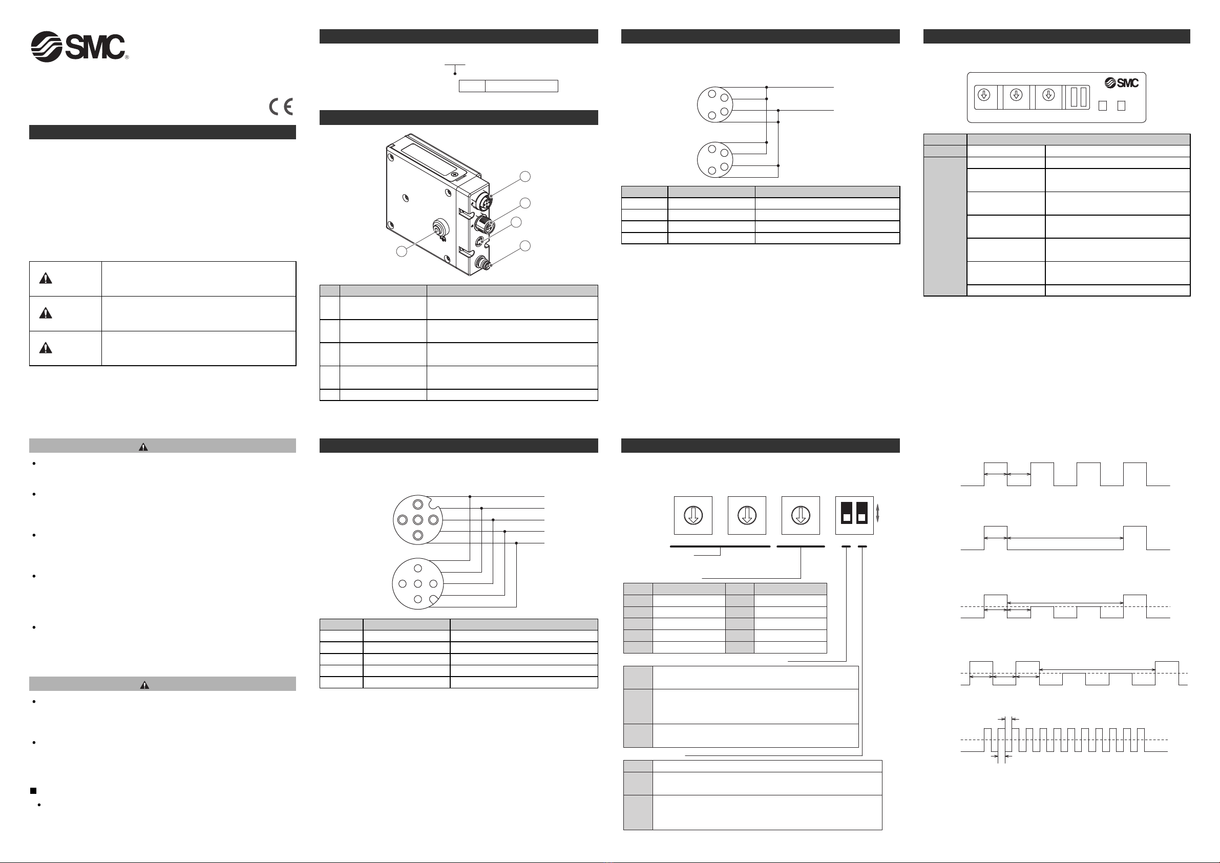
Summary of Pro uct elements
o. Element Description
1Communication
connector BUS OUT
Connect to CA open communication line
and power supply for communication (OUT).
2Communication
connector BUS I
Connect to CA open communication line
and power supply for communication (I ).
3Power supply
connector PWR OUT
Connect to the power supply for solenoid
valve (OUT).
4Power supply
connector PWR I
Connect to the power supply for solenoid
valve (I ).
5 FG terminal Used for functional ground.
1
2
3
4
5
1
2
3
4
5
CAN_SHLD
CAN_V+
CAN_GND
CAN_H
CAN_L
BUS OUT
(Socket (female))
BUS IN
(Plug (male)) 1
2
3
45
1
2
3
45
Pin o.
1
2
3
4
5
Description
CA _SHLD
CA _V+
CA _G D
CA _H
CA _L
Function
Shield
Power supply + for CA open
Power supply - for CA open
CA _H bus line (dominant high)
CA _L bus line (dominant low)
Wiring
•Internal wiring of communication connectors
Communication connector (M12 plug (male)/socket (female) 5 pins)
BUS connector cable: M12 5 pins cable with shield
(according to ISO11898))
The permissible current of the internal wiring (CA _V + and CA _G D)
between communication connectors is 2 Amps maximum.
Safety Instructions
This manual contains essential information for the protection of users
and others from possible injury and/or equipment damage.
•Read this manual before using the product, to ensure correct handling,
and read the manuals of related apparatus before use.
•Keep this manual in a safe place for future reference.
•These instructions indicate the level of potential hazard by label of
"Caution", "Warning" or "Danger", followed by important safety
information which must be carefully followed.
•To ensure safety of personnel and equipment the safety instructions in
this manual and the product catalogue must be observed, along with
other relevant safety practices.
CAUTIO indicates a hazard with a low level of risk
which, if not avoided, could result in minor or
moderate injury.
Caution
Warning
Danger
WAR I G indicates a hazard with a medium level
of risk which, if not avoided, could result in death or
serious injury.
DA GER indicates a hazard with a high level of risk
which, if not avoided, will result in death or serious
injury.
This product is class A equipment that is intended for use in an industrial
environment.
There may be potential difficulties in ensuring electromagnetic
compatibility in other environments due to conducted as well as radiated
disturbances.
Do not isassemble, mo ify (inclu ing changing the printe
circuit boar ) or repair.
An injury or failure can result.
Do not operate the pro uct outsi e of the specifications.
Do not use for flammable or harmful fluids.
Fire, malfunction, or damage to the product can result.
Verify the specifications before use.
Do not operate in an atmosphere containing flammable or
explosive gases.
Fire or an explosion can result.
This product is not designed to be explosion proof.
If using the pro uct in an interlocking circuit:
•Provide a double interlocking system, for example a mechanical
system.
•Check the product regularly for proper operation.
Otherwise malfunction can result, causing an accident.
The following instructions must be followe uring maintenance:
•Turn off the power supply.
•Stop the air supply, exhaust the residual pressure and verify that the
air is released before performing maintenance.
Otherwise an injury can result.
Warning
NOTE
When conformity to UL is required, the SI unit should be used with a
UL1310 Class 2 power supply.
Caution
After maintenance is complete, perform appropriate functional
inspections.
Stop operation if the equipment does not function properly.
Safety cannot be assured in the case of unexpected malfunction.
Provi e groun ing to assure the safety an noise resistance of
the Fiel bus system.
Individual grounding should be provided close to the product with a
short cable.
2
3
4
1
2
3
4
1
+24 V for
solenoid valve
0 V for
solenoid valve
PWR OUT
(Socket (female))
PWR IN
(Plug (male))
4
2
3
1
4
2
3
1
Pin o.
1
2
3
4
Description
SV 24 V
SV 24 V
SV 0 V
SV 0 V
Function
+24 V for solenoid valve
0 V for solenoid valve
Wiring (continue )
•Internal wiring of communication connectors
Power supply connector (M8 plug (male)/socket (female) 4 pins)
(Connector caable: M8 4 pins cable)
The permissible current of the internal wiring (SV24 V-SV0 V) between
power supply connectors is 4 Amps maximum.
Setting of output when communication stops
Setting of Node-ID
The setting range is 1-99. (0 is invalid)
Setting of mode
SW1
x10 x1
SW2
BAUD SETTINGS
SW3 SW4
Setting of Baud Rate
SW3
The output shall use the pre-defined condition specified
in the Error Value Output Object (6207h, 6307h, 6327h).
Default: All outputs are cleared (OFF).
All outputs are held in the state immediately before the
communication stopped.
State of solenoid valve output when error (Error Control,
Emergency Object) occurs or fault message is received.
SW4-1
0
1
SW mode. Setting of Node-ID is achieved via network. SW1 and
SW2 become unavailable. Node-ID can be set up to 127.
Default is 127 (7Fh).
HW mode. Setting of Node-ID is achieved using SW1 and SW2.
Setting of
Baud Rate
is achieved using SW3.
Mode
SW4-2
0
1
0
1
2
3
4
Baud Rate [kbps]
1000
800
500
250
125
6
5
7
8
9
50
Reserved
20
10
Reserved
SW3 Baud Rate [kbps]
0
5
2
7
8
3
9
4
1
6
0
5
2
7
8
3
9
4
1
6
0
5
2
7
8
3
9
4
1
6
ON
OFF
12
Setting
•Internal wiring of communication connectors
Communication connector (M12 plug (male)/socket (female) 5 pins)
Indication
PWR(V)
CA
Content
Green Light
Green Light
Green Light
(flashing)
Green Light
(single flash)
Red Light
(single flash)
Red Light
(double flash)
Green/Red Light
(flashing)
Red Light
Power for solenoid valves is supplied
SI unit is in the Operational state
SI unit is in the Pre-Operational state
SI unit is in Stopped state
CA controller error occured
Error Control Event occured
SI unit is in Configuration mode
(LSS services)
SI unit is in "Bus OFF" state
Setting (continue )
•LED indication
Green (flashing): Pre-Operational State
NODE-ID
X10 X1 BAUD
SETTINGS CAN PWR(V)
Green
LED ON
Green
LED OFF
200 ms 200 ms
Green (Single Flash): Stopped State
Green
LED ON
Green
LED OFF
200 ms
1000 ms
Red (Single Flash): CA controller error
Red
LED ON
Green
LED ON
200 ms 200 ms
1000 ms
OFF
Red (Double Flash): Error Control Event
Red
LED ON
Green
LED ON
200 ms 200 ms 200 ms
1000 ms
OFF
Green/Red (flashing): LSS Configuration Mode
Red
LED ON
Green
LED ON 50 ms
50 ms
OFF
∗: LED Indication of SI unit is based on CA open specification
(CA open spec. DR-303-3).
Refer to DR-303-3 indicator specification for details.
EX260-TFQ01
Solenoid valve manifoldSI unit
M3 hexagon screw
Tightening torque: 0.6 Nm
BUS OUT
BUS IN
PWR OUT
PWR IN
5 EA
3 EB
1P
5 EA
3 EB
1P
2
4
B
A
2
4
B
A
2
4
B
A
2
4
B
A
2
4
B
A
2
4
B
A
2
4
B
A
2
4
B
A
request request
indication indication
indication
indication
Unconfirmed
service
Application X Application Y, Z, ...
confirmation response
Confirmed
service
Application X Application Y
Maintenance
How to reset the product after the power has been disconnected
The output condition of the SI unit will not be stored by the product if
the power supply is disconnected.
Be sure to confirm safety before operating the product, after the power
has been restored.
Maintenance
•Exchange of SI unit
(1) Remove hexagonal M3 screw and release the connection to the
valve manifold.
(2) Replace the SI unit.
(3) Tighten the screw using the specified tightening torque. (0.6 m)
CAUTION FOR MAINTENANCE
(1) Be sure to turn-off all power supplies.
(2) Be sure that there are no foreign objects in any of the units.
(3) Be sure that the gasket is positioned correctly.
(4) Be sure that the tightening torque is according to specification.
If these precautions are not taken, it may lead to damage to the unit,
or intrusion of liquid or dust into the unit.
Assembly and disconnection of unit
It is the responsibility of the machine builder to make sure that the
machine operates correctly.
CA open units from different manufacturers have different ability
(minimum message interval) respectively.
The machine builder should consider the differences in the ability.
The method (confirmed service) of sending the following request, after
receiving the response to the request, is recommended, to ensure
correct communication.
When using the method (unconfirmed service) of sending the following
request, without receiving a response to the request, if the request
exceeding the processing performance of the unit is sent, it cannot be
received.
Please confirm the normal operation beforehand when an SMC
CA open unit is used in your machine.
Please consult with SMC when there is a problem.
Specifications
Refer to the operation manual for this product.
Outline with Dimensions (in mim)
Refer to the operation manual for this product.
Caution
URL http://www.smcworld.com (Global) http://www.smceu.com (Europe)
Specifications are subject to change without prior notice from the manufacturer.
© 2012 SMC Corporation All Rights Reserved
Contacts
AUSTRIA (43) 2262 62280-0
ETHERLA DS (31) 20 531 8888
BELGIUM (32) 3 355 1464
ORWAY (47) 67 12 90 20 CZECH REP. (420) 541 424 611
POLA D (48) 22 211 9600 DE MARK (45) 7025 2900
PORTUGAL (351) 21 471 1880
FI LA D (358) 207 513513
SLOVAKIA (421) 2 444 56725 FRA CE (33) 1 6476 1000
SLOVE IA (386) 73 885 412GERMA Y (49) 6103 4020
SPAI (34) 945 184 100 GREECE (30) 210 271 7265
SWEDE (46) 8 603 1200 HU GARY (36) 23 511 390
SWITZERLA D (41) 52 396 3131 IRELA D (353) 1 403 9000
U ITED KI GDOM (44) 1908 563888 ITALY (39) 02 92711
BULGARIA (359) 2 974 4492
ESTO IA (372) 651 0370
ROMA IA (40) 21 320 5111
LATVIA (371) 781 77 00
LITHUA IA (370) 5 264 8126

Other SMC Networks Industrial Equipment manuals

SMC Networks MHZ2-6C-M9PLS User manual

SMC Networks

SMC Networks MHZ2-6C-M9PLS User manual

SMC Networks EX260-VPN1 User manual

SMC Networks

SMC Networks EX260-VPN1 User manual

SMC Networks JSY5000-H Series User manual

SMC Networks

SMC Networks JSY5000-H Series User manual

SMC Networks LFE series User manual

SMC Networks

SMC Networks LFE series User manual

SMC Networks HECR Series Use and care manual

SMC Networks

SMC Networks HECR Series Use and care manual

SMC Networks EX510-DYN3 User manual

SMC Networks

SMC Networks EX510-DYN3 User manual

SMC Networks CY3R Series User manual

SMC Networks

SMC Networks CY3R Series User manual

SMC Networks ZXP7-X1-ASSISTA Series User manual

SMC Networks

SMC Networks ZXP7-X1-ASSISTA Series User manual

SMC Networks PSE550 User manual

SMC Networks

SMC Networks PSE550 User manual

SMC Networks MGJ Series User manual

SMC Networks

SMC Networks MGJ Series User manual

SMC Networks HEBC002-WA10 User manual

SMC Networks

SMC Networks HEBC002-WA10 User manual

SMC Networks SFDA Series User manual

SMC Networks

SMC Networks SFDA Series User manual

SMC Networks ZXP7 11 X1 Series User manual

SMC Networks

SMC Networks ZXP7 11 X1 Series User manual

SMC Networks CE Series User manual

SMC Networks

SMC Networks CE Series User manual

SMC Networks EtherCAT EX260-VEC1 User manual

SMC Networks

SMC Networks EtherCAT EX260-VEC1 User manual

SMC Networks LEHR Series User manual

SMC Networks

SMC Networks LEHR Series User manual

SMC Networks ZL3 Series User manual

SMC Networks

SMC Networks ZL3 Series User manual

SMC Networks MY3A Series User manual

SMC Networks

SMC Networks MY3A Series User manual

SMC Networks SY3000 SERIES User manual

SMC Networks

SMC Networks SY3000 SERIES User manual

SMC Networks CP96N Series User manual

SMC Networks

SMC Networks CP96N Series User manual

SMC Networks CYV Series User manual

SMC Networks

SMC Networks CYV Series User manual

SMC Networks EX260-SPN1 User manual

SMC Networks

SMC Networks EX260-SPN1 User manual

SMC Networks ZKJ Series User manual

SMC Networks

SMC Networks ZKJ Series User manual

SMC Networks MHK2-12 Series User manual

SMC Networks

SMC Networks MHK2-12 Series User manual

Popular Industrial Equipment manuals by other brands

Siemens Sivacon S8 operating instructions

Siemens

Siemens Sivacon S8 operating instructions

riverhawk IM-255 instruction manual

riverhawk

riverhawk IM-255 instruction manual

Black Splitter S2 Original operating instructions

Black Splitter

Black Splitter S2 Original operating instructions

ABB HT573279 Operation manual

ABB

ABB HT573279 Operation manual

PI F-712.HA1 user manual

PI

PI F-712.HA1 user manual

JUKI KE-750 Setup guide

JUKI

JUKI KE-750 Setup guide

Jäger Z62-H370.01 S5W2 manual

Jäger

Jäger Z62-H370.01 S5W2 manual

Traub TNL20 operating instructions

Traub

Traub TNL20 operating instructions

ABB HT563866 Operation manual

ABB

ABB HT563866 Operation manual

Romus 94575 operating manual

Romus

Romus 94575 operating manual

Rupes HTE 300 START-UP, OPERATING AND MAINTENANCE INSTRUCTIONS

Rupes

Rupes HTE 300 START-UP, OPERATING AND MAINTENANCE INSTRUCTIONS

IDEC SX5A AS-Interface manual

IDEC

IDEC SX5A AS-Interface manual

Wilo Isar BOOST5 Installation and operating instructions

Wilo

Wilo Isar BOOST5 Installation and operating instructions

Precision X40 MSE Operational manual

Precision

Precision X40 MSE Operational manual

ABB HT608449 Operation manual

ABB

ABB HT608449 Operation manual

AHCON TL2.0 user manual

AHCON

AHCON TL2.0 user manual

Eagle EV-30 owner's manual

Eagle

Eagle EV-30 owner's manual

ABB RELION 650 SERIES Product guide

ABB

ABB RELION 650 SERIES Product guide

manuals.online logo
manuals.online logoBrands
  • About & Mission
  • Contact us
  • Privacy Policy
  • Terms and Conditions

Copyright 2025 Manuals.Online. All Rights Reserved.