Toolshop 240-2003 User manual
SAVE THIS MANUAL
You will need this manual for safety instructions, operating procedures and warranty.
Put it and the original sales receipt in a safe dry place for future reference.
For questions about this product, please call 1-866-915-8626.
Operator’s Manual
240-2003
8IN. DRILL PRESS

WARNING:
1
When using electric tools, machines or equipment, basic safety
precautions should always be followed to reduce the risk of fire,
electric shock, and personal injury.
IMPORTANT SAFETY INSTRUCTION
READALL INSTRUCTIONS BEFORE USING THIS TOOL
1. KEEP WORKAREA CLEAN. Cluttered areas invite injuries.
2. CONSIDERWORKAREA ENVIRONMENT. Don’t use power tools in damp,
wet, or poorly lit locations. Don’t expose your tool to rain. Keep the work area
well lit. Don’t use tools in the presence of ammable gases or liquids.
3. KEEP CHILDREN ANDBYSTANDERSAWAY.All children should be kept
away from the work area. Don’t let them handle machines, tools or extension
cords. Visitors can be a distraction and are difcult to protect from injury.
4. GROUNDEDTOOLS must be plugged into an outlet that itself is properly
installed and grounded. Grounding provides a low-resistance path to carry
electricity to ground away from the operator, should the tool malfunction elec-
trically. Do not remove the grounding prong from the plug or alter the plug in
any way. If in doubt as to whether the outlet is properly grounded according
to code, check with a qualied electrician.
5. OBSERVE PROPERPRECAUTIONS REGARDING GROUNDEDPLUG.
Plug power cord into a 110-120V properly grounded type outlet protected by a
12 amp time delay, a circuit saver fuse or circuit breaker.
6. GUARD AGAINST ELECTRIC SHOCK. Prevent body contact with grounded
surfaces: pipes, radiators, ranges, and refrigerator enclosures. When your
body is grounded the risk of electric shock increases. When working wherever
“live” electrical wires may be encountered, try to ascertain whether there is
a danger of shock. Even so, DO NOT TOUCH ANY METAL PARTS OF THE
TOOL while using it.
7. HANDLE THE CORD CAREFULLY. Never pull on the cord to unplug this tool.
Protect the cord from potential sources of damage:heat, oil & solvents, sharp
edges, or moving parts. Replace damaged cords immediately.
8. WHEN WORKING OUTDOORS, USE AN OUTDOOR-RATEDEXTENSION
CORD.An extension cord rated for outdoor use must be marked “W-A” or
“W”.
9. DO NOT EXPOSE ELECTRICAL POWERTOOLS TO MOISTURE. Rain or
wet conditions can cause water to enter the tool and lead to electric shock.
10. ENSURE THE EXTENSION CORD YOU USE IS OF SUFFICIENT GAUGE
FORITS LENGTH.
Recommended Minimum Wire Gauge for Extension Cords
Amps
from
Tool Nameplate
25’(7 m) length 50’(15 m)length 75’(23 m)length 100’(30 m) length 150’ (46 m)length 200’(61 m)length
0-5 amps 16 ga. 16 ga. 16 ga. 14 ga. 12 ga. 12 ga.
5.1-8 amps 16 ga. 16 ga. 14 ga. 12 ga. 10 ga. Do Not Use
8.1-12 amps 14 ga. 14 ga. 16 ga. 10 ga. Do Not Use Do Not Use
12.1-15 amps 12 ga. 12 ga. 10 ga. 10 ga. Do Not Use Do Not Use
15.1-20 amps 10 ga. 10 ga. 10 ga. Do Not Use Do Not Use Do Not Use
11. STORE IDLE EQUIPMENT. Store equipment in a dry area to inhibit rust.
Equipment also should be in a high location or locked up to keep out of reach
of children.
12. DON’T FORCE THE TOOL. It will do the job better and more safely at the
rate for which it was intended.
13. USE THE RIGHT TOOL. Don’t force a small tool or attachment to do the work
of a larger industrial tool. Don’t use a tool for a purpose for which it was not intended.

2
IMPORTANT SAFETY INSTRUCTION
contain long hair and keep it from harm.
15. USE EYE PROTECTION. Use a full-face mask if the work you’re doing produces
Goggles are acceptable in other situations.
Wear a clean dust mask if the work involves creating a lot of ne or coarse
dust.
16. SECURE WORK. Use clamps or a vise to hold the work. It’s safer than using
your hands and it frees both hands to operate the tool.
17. DON’T OVERREACH. Keep proper footing and balance at all times. Do not
reach over or across tools that are running.
18. MAINTAIN TOOLS WITH CARE. Keep tools sharp and clean for better and
safer performance. Follow instructions for lubricating and safe performance.
Follow instructions for lubricating and changing accessories. Keep handles dry,
clean and free from oil and grease.
19. AVOIDUNINTENTIONAL STARTING. Be sure the switch is in the OFF position
before plugging in.
20. ALWAYS CHECK ANDMAKE SURE TO REMOVE ANY ADJUSTING KEYS
ORWRENCHES before turning the tool on. Left attached, these parts can y
off a rotating part and result in personal injury.
21. DO NOT USE THE TOOL IF IT CANNOT BE SWITCHEDON OROFF. Have
your tool repaired before using it.
22. DISCONNECT THE PLUG FROM POWERBEFORE MAKING ANY AD-
JUSTMENTS. Changing attachments or accessories can be dangerous if the
tool could accidentally start.
23. STAY ALERT. Watch what you are doing & use common sense. Don’t operate
any tool when you are tired.
24. CHECK FORDAMAGEDPARTS. Before using this tool, any part that is dam-
aged should be carefully checked to determine that it will operate properly and
perform its intended function. Check for alignment of moving parts, binding
of moving parts, breakage of parts, mountings, and other conditions that may
affect its operation. Inspect screws and tighten any ones that are loose. Any
part that is damaged should be properly repaired or replaced by an authorized
service center unless otherwise indicated elsewhere in the instruction manual.
Have defective switches replaced by an authorized service center. Don’t use
the tool if switch does not turn it on and off properly.
25. REPLACEMENT PARTS. When servicing, use only identical replacement parts.
26. SERVICE ANDREPAIRSshould be made by qualied repair technicians at an
authorized repair center. Improperly repaired tools could cause serious shock
or injury.
14. DRESS PROPERLY. Don’t wear loose clothing or jewelry; they can be caught
in moving parts. Protective, non-electrically conductive gloves and non-skid
footwear are recommended when working. Wear protective hair covering to
SAFETY PRECAUTIONS FORDRILL PRESS
WARNING: Do not operate your drill press until it is completely
assembled and installed according to the instructions.
1. Never turn on the drill press before clearing the table of all objects (tools,
scraps, etc.).
2. Always keep hands and fingers away from the drill bit.
3. Do not drill material that does not have a flat surface, unless a suitable
support is used.
4. Never start the drill press with the drill bit pressed against the workpiece.
5. Make sure the table lock is tightened before starting the machine.
!

SAFETY PRECAUTIONS FORDRILL PRESS
3
!
!
WARNING - ngers touch the terminals of the plug when installing
or removing the plug to or away from the outlet.
WARNING - If not properly grounded, this tool can incur the potential hazard
of electrical shock particularly when used in damp locations or in proximity to
plumbing. If an electrical shock occurs, there is the potential of a secondary hazard
like your hands contacting the tool.
Electricity Requirements
CONNECTING THE TOOL TO A POWERSOURCE OUTLET
This machine source must be grounded while in use to protect the operator from
electric shock. In case of malfunction or breakdown, grounding provides a path
of least resistance for electrical current to reduce the risk of electrical shock. This
tool is equipped with an electric cord having an equipment grounding conductor
outlet that is properly installed and grounded in accordance with all local codes
and ordinances.
Improper connections of the equipment-grounding conductor can result in a risk of
electrical shock. The conductor with insulation having an outer surface that is green
(with or without yellow strips) is the equipment-grounding conductor. If repair or
replacement of the electric cord or plug is necessary, do not connect the equipment-
grounding conductor to a live terminal.
Plug power cord into a 120V properly grounded type outlet protected by a 3.0A
time delay, a circuit saver fuse or circuit breaker.
Protect Your Eyes
The operation of any power tool can result in foreign objects being thrown into the
eyes, which can result in severe eye damage. Always wear eye protection during
operation of the tool.
FIGURE 1
GROUNDING PRONG
PROPERLY GROUNDEDTHREE
PRONG OUTLET
THREE PRONG PLUG
This tool is intended for use on a circuit that has an outlet that looks like the one in
Figure 1.
6. Never perform layout, assembly, or set-up work on the table while the drill
is in use.
7. Make sure drill bit is securely locked in the chuck.
8. Make sure chuck key is removed from the chuck before turning power on.
9. Adjust the table or depth stop to avoid drilling into the table.
10. Always stop the drill before removing scrap pieces from the table.
11. Use clamps or a vise to secure workpiece to the table. This will prevent
workpiece from rotating with the drill bit.
12. Do not wear gloves when operating a drill press.
13. Shut the power off, remove the drill bit, and clean the table before leaving
the drill press.
14. Set the drill press to the speed appropriate for the job.
15. Should any part of your drill press be missing, damaged, or any electrical
component fail to perform properly, shut power off and unplug the drill press.
Replace missing, damaged, or failed parts before resuming operation.
Do not modify the plug provided. If the plug does not t the proper
outlet, have a proper outlet installed by a qualied electrician.
4
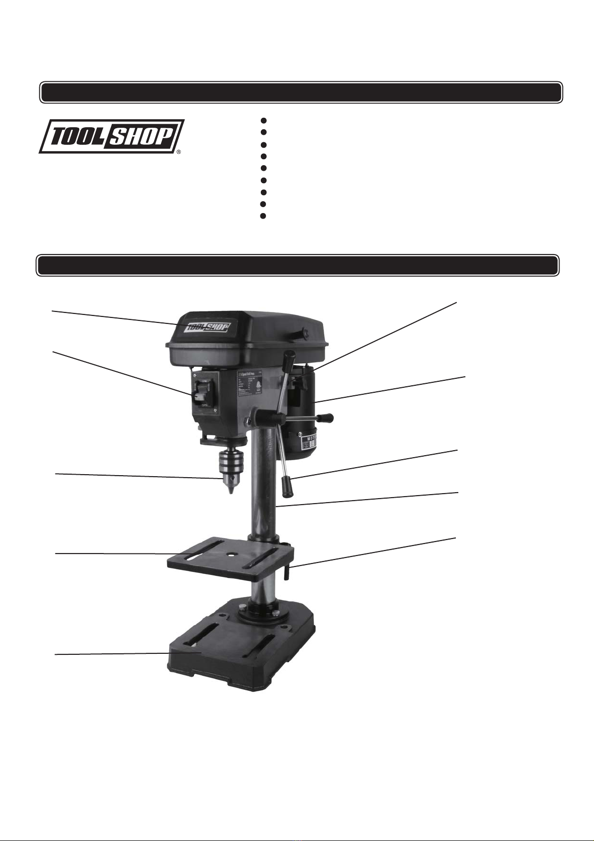
FUNCTION DESCRIPTION
1
2
3
4
5
10
9
8
7
6
Voltage: 120V ~ 60Hz,
Current Rating: 3.0 Amps
Spindle Speed: 740, 1100, 1530, 2100, 3140 RPM (No Load)
Chuck Capacity: 1/2"
Spindle travel: 2"
Spindle Attachment: JT33
Table Height Adjustment: 8-1/2"
Swing: 8"
Contents:(1) Chuck Key
(2) 1/8" & 5/32" hex wrench, Product Manual
SPECIFICATIONS
1. Belt cover
6. Lock handle
2. On/Off Switch
7. Column assembly
3.
8. Motor
4. Work table
Chuck
9. Handle
5. Base
10. Belt tension lock knob

5
ASSEMBLY ANDADJUSTMENTS
WARNING: To reduce the risk of injury, never connect plug to power source
outlet until all assembly steps are completed.
Base to column
1. Place Colum
(See Fig. 2)
(See Fig. 1)
(See Fig. 3)
n (1) on the Base (3) and align holes
in the Column with holes in the Base.
2. Attach using Bolt, Spring Washer,and Washer
(2) in each hole through the Column and into the
Base.
Table to column
1. Loosen the Lock handle (3) on the table. (2).
2. Slide the Table(2) over the Column (1).
3. Tighten the Lock handle (3) to secure the Table (2)
in place.
Drill press head to column
1. Lift the drill press head assembly (1) carefully and
place the mounting hole of the drill press head onto
the top of the column (3). Make sure the head is
seated properly on.
2. Align the direction of the drill press head to the
direction of the base and the table.
3. Tighten the set screws (2) using the 5/32" hex wrench.
4. Thread the handle rods (4) into the holes on the hub.
5. Hand tighten.
Note:One or two of the handles may be removed
unusually
if an
-shaped workpiece interferes with handle
rotation.
1
2
3
1
2
3
Fig. 1
Fig. 2
1
Fig
1
1
F
i
Fig. 3
1
2
3
4

ASSEMBLY ANDADJUSTMENTS
Install the chuck (see Fig. 4 ).
1. Inspect and clean the taper hole in the chuck and the spindle.
Remove all grease, coatings, and particles from the chuck and
spindle surfaces with a clean cloth.
2. Open the chuck jaws by turning the chuck barrel clockwise by
hand. Make sure the jaws are completely recessed inside the
chuck.
3. Seat the chuck on the spindle by placing a block of wood
under the chuck and tapping the wood with a hammer or
tap the chuck with a rubber mallet.
Removethe chuck at alater time
1. Turn the feed handles to lower the chuck (1) to the lowest position.
2. Place a ball joint separator tool (4) above the chuck (2) and tap it
lightly with a hammer (3) to cause the chuck to drop from the
spindle.
Note:This ball joint separator tool not included and sold separately.
Note: To avoid possible damage, be prepared to catch the chuck
as it falls.
CAUTION: To avoid damaging the chuck, make sure the jaws are
completely recessed into the chuck. Do not use a metal
hammer directly to drive the chuck into the spindle.
Install the belt
1. Open the pulley and belt cover (1).
2. Loosen the belt tension lock knob (2).
3. Slide the motor (3) as close to the drill press head as possible.
4. Place a belt (4) on the motor pulley (5) and the spindle pulley
(6) in the proper position for the desired speed.
5. Pull the motor away from the drill press head until the belt is
properly tensioned. Tighten the belt tension lock knobs.
Note:The belt (4) should be tight enough to prevent slippage.
Correct tension is set if the belt flexes about 1/2" (13 mm) when
thumb pressure is applied at the midpoint of the belt
pulleys.
between the
1
23
4
5
6
Spindle speeds
This drill press offers 5 spindle speeds from 740 to 3140 RPM.
The highest speed is obtained when the belt is positioned on
the largest motor pulley step and the smallest spindle pulley step.
(see Fig. 6 and Fig. 7).
(The belt is included).
(see Fig. 5 ).
6
Fig. 4
Fig. 6
Fig. 7
!
Fig. 5
1
2
4
13
2
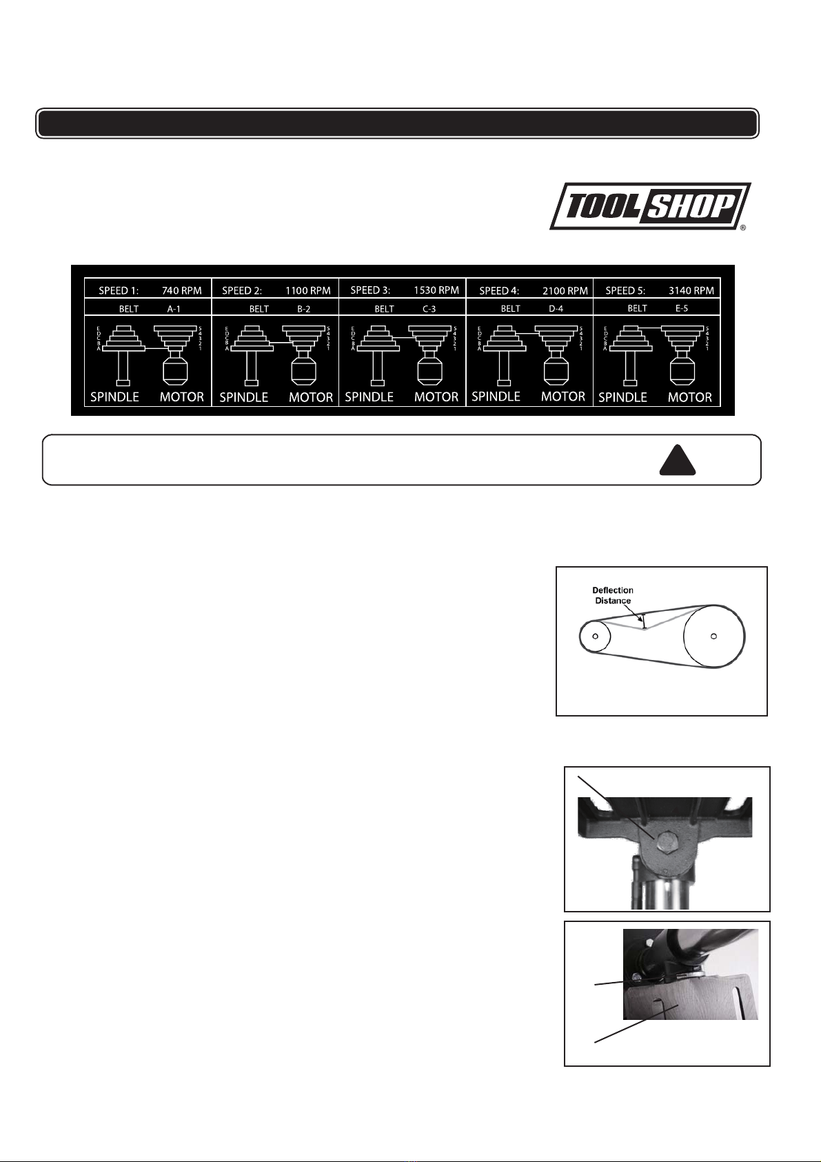
ASSEMBLY ANDADJUSTMENTS
WARNING: Disconnect the drill press from the power source before
making any speed adjustments.
Adjust speeds and tension the belt
1. Open the drill press pulley cover.
2. Loosen the belt tension knob (2) (see Fig 7).
3. Pull the motor (3) (see Fig. 7) toward the drill press head.
4. Set the belt on the desired steps of the motor and spindle
pulleys
chart
according to the belt positions on the spindle speed
. (See above chart)
5. Pull the motor away from the drill press head to increase
the belt tension.Tighten the tension knobs (2) (see Fig. 7).
(see Fig. 9 and Fig. 10).
6. The belt should be tight enough to prevent slippage. Correct
tension is set if the deflection distance is about 1/2" (13 mm)
when thumb pressure is applied at the midpoint of the belt
between the pulleys.
Tilt the table
The table can be tilted from 0 to 45° to the left and right.
1. Loosen the bevel lock bolt (1) with a 3/4" hex wrench.
2. Tilt the table (2) to the desired angle, using the bevel scale (3)
as a basic guide.
3. Re- tighten the bevel lock bolt (1).
4. To return the table to its original position, loosen the bevel lock
bolt. Realign the bevel scale (3) to the 0° setting.
5. Tighten the bevel lock bolt (1) with the 3/4" hex wrench.
Note: This 3/4” hex wrench is not included and sold separately.
1
2
3
7
Fig. 8
Fig. 9
Fig. 10
!
(See Fig. 11)
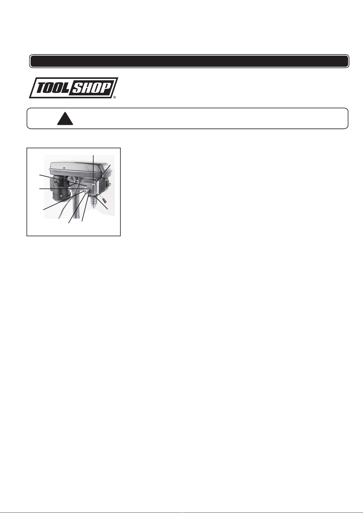
ASSEMBLY ANDADJUSTMENTS
Coil spring adjustment
WARNING: Disconnect the drill press from the power source
before adjustment .
If the quill (8) returns too quickly or too slowly when the handles
are released, adjust the spring.
Note: This adjustment is set at the factory and should not need
changing. Re-adjustments may eventually be necessary due to
normal wear and tear.
1. Raise the spindle to the top position.
2. Move both depth scale nuts (1) to the lowest position and
tighten to prevent the quill from dropping down.
3. Place a screwdriver in the notch (2) of the spring housing.
4. Firmly hold the screwdriver in place to prevent the spring
and housing from moving.
5. Loosen and remove the outer jam nut (3).
6. Loosen, BUT DO NOT REMOVE, the inner nut (4).
7. Pull out, BUT DO NOT REMOVE, the housing (5) from the
raised lug (6) on the drill press head.
8. With the screwdriver in the notch, carefully turn the spring
housing(5) counter-clockwise until the next notch engages
with the raised lug.
9. Release the housing and tighten the inner nut (4). Do not
remove the screwdriver.
10. Check the quill (8) tension
Move the two stop nuts(1) on the depth scale rod to the
top position.
Turn the handles and release, raising the depth
pointer (7) to the top position. If there is not enough
tension, repeat steps 6- 9, moving the spring housing
one more notch. If there is too much tension, move
the housing one notch at a time in the opposite
direction.
8
Fig. 11
25
3
4
6
1
7
8
!
ASSEMBLY ANDADJUSTMENTS
11. If the quill (8) returns gently to top position (correct operation):
Tighten the inner nut (4). Do not overtighten.
Replace the jam nut (3). Tighten against the inner nut.
Remove the screwdriver.
Rotate the handles and check the quill (8) for unrestricted
movement.
12. If the quill (8) movement is too restricted or tight:
Loosen the jam nut (3).
Slightly loosen the housing inner nut (4).
Tighten the jamnut (3).
Check the quill (8) movement again and repeat steps 1-3
until the quill (8) moves freely.
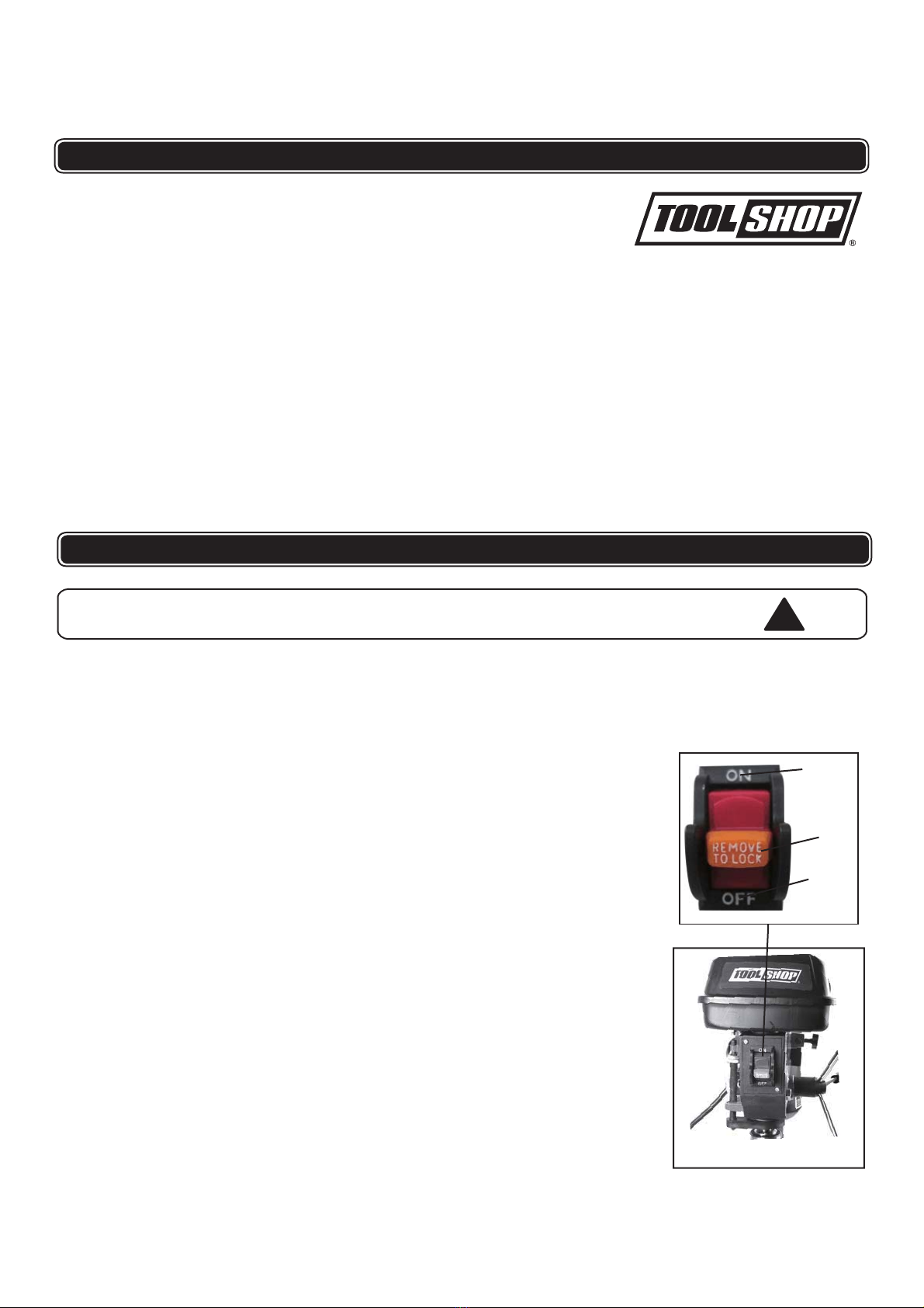
Safety Switch: Insert the Safety Key (Fig 12) into the Switch. This
“Key” is a safety precaution and should remain in the Switch during
use and be removed after Switch is turned off and/or any time the
Drill Press is left unattended or in storage.
OPERATION
WARNING:
9
TURNING ON AND OFF
Note:The pulley cover must be closed to operate the drill press.
Risk of injury due to accidental starting. Do not use in an
area where children may be present.
(Fswitch.
clamps.
switch.
ig 12).
(Fig 12).
1. Switch the drill press on by pressing the “ON” button on the
2. Switch the drill press off by pressing the “OFF” button on
the
3. Secure your workpiece to the table if possible, using a vice or
!
OFF
Safety
Key
ON
Fig. 12

OPERATION
Check the belt tension after the first 3-5 hrs. of operation to ensure
that the belts have not become stretched and loose from their
'breaking in' use.
MAINTAINING YOURDRILL PRESS
WARNING:
Before each use:
1. Check the power cord and plug for any wear or damage.
2. Check for any loose screws or hardware.
3.
4.
5.
Check the area to make sure it is clear of any misplaced
lumber, cleaning supplies, etc. that could
tools,
hamper the
operation of the drill press.
safe
To avoid a build-up of wood dust, regularly clean all parts
of the machine using a soft cloth, brush or compressed air.
A general cleaning should be done after every use to avoid
future problems and ensure the machine is in ready condition
for the next time it is used.
WARNING: If blowing sawdust, wear proper eye protection to prevent
debris from blowing into eyes. The use of dust collection
is also advised.
Keep the table, column and base free of resin and rust. Clean them
regularly with a non -flammable
of dry lubricant spray, or wax, to keep their surfaces clean. Do not
use
solvent, then coat with a light film of
ordinary dustoil which will collect and hamper the operation of
the machine.
All of the ball bearings are lifetime lubricated, sealed, and do not
need any further care. Keep the drive belts free of oil and grease.
10
4. Select your drilling depth and secure the depth stop lock knob in
position.
5. Adjust the table to your desired position.
6. Slowly rotate the wheel handles to bring the drill bit down towards
the table and into your workpiece. After drilling a hole, release the
wheel handles slowly to return the chuck to its original position.
7. Continue the operation until the task is completed. When
completed, switch the drill press off by pressing the “OFF button
on the switch.
Turn the power switch “OFF” and disconnect the plug from
the outlet prior to adjusting or maintaining the machine.
DO NOT attempt to repair or maintain the electrical
components of the motor. Contact a qualified service
technician for this type of maintenance.
!
!

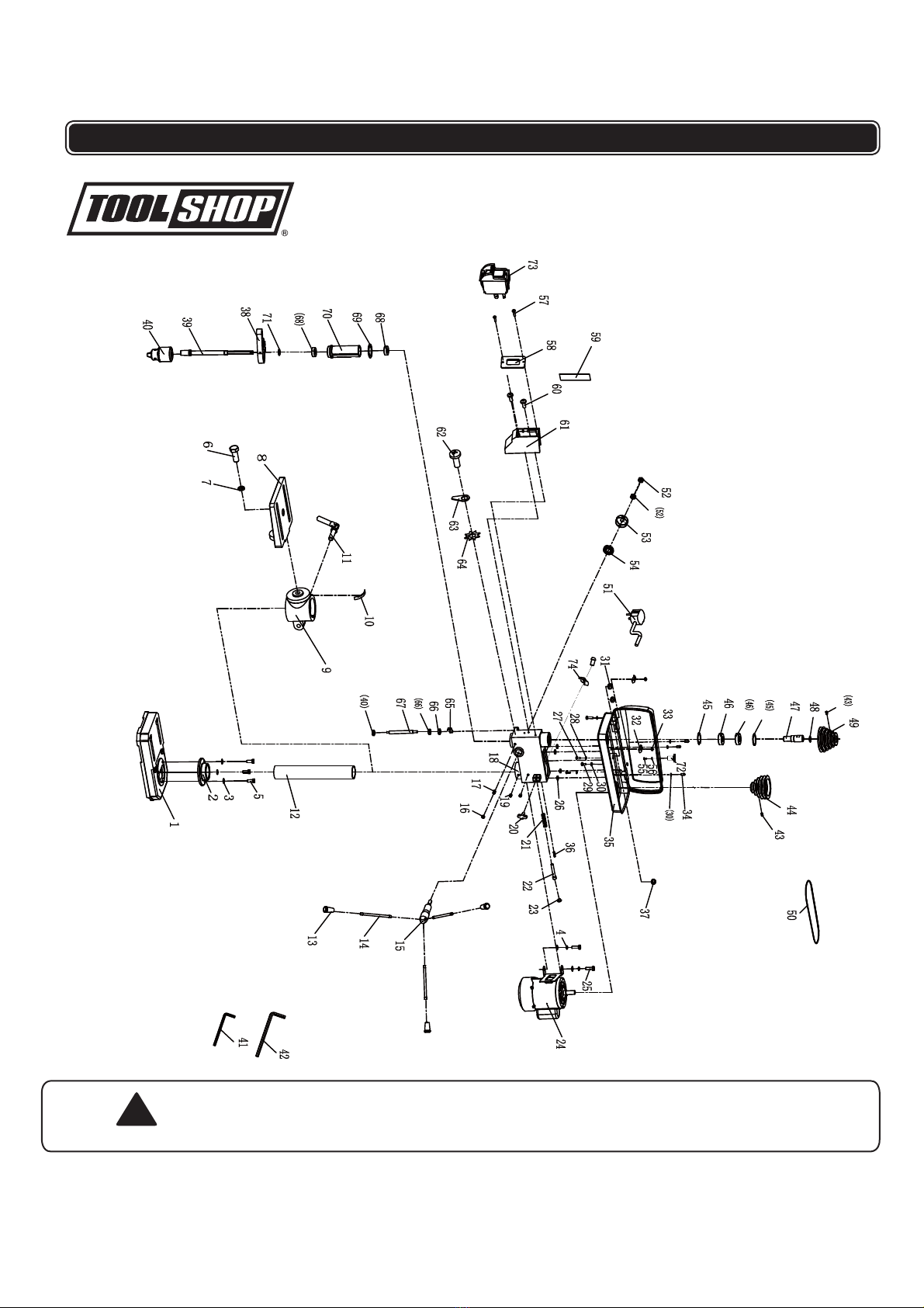
PARTS LIST ANDSCHEMATIC DRAWING
11
12 '(6&5,37,2 21
1 BASE
2 COLUMN FLANGE
3FLATWASHER
4 SPRING WASHER
5 OUTSIDE HEX. BOLT
6 OUTSIDE HEX. BOLT
7 SPRING WASHER
8WORKINGTABLE
9 TABLE SUPPORT
10 ANGLE LABEL
11 LOCKING HANDLE
12 COLUMN
13 HANDLE TIP
14 HANDLE
15 GEAR SHAFT
16 NUT
17 HEAD SCREW
18 HOUSING
19 HEX. SOC SET SCREW
20 WING KNOB
21 MOTOR SPRING
22 MOTOR BOLT
23 WASHER
24 MOTOR
25 OUTSIDE HEX. BOLT
26 DAMPING WASHER
27 CROSS RECESS PAN HD SCREW
28 FLAT WASHER
29 CROSS RECESS PAN HD SCREW
30 FLAT WASHER
31 PROTECTOR RING
32 CORD CLAMP
33 NUT
34 CROSS RECESSED PAN HEAD SCREW
35 PULLEY COVER ASSEMBLY
36 ROLL PIN
37 PROTECTOR RING
38 RULER HOLDER
39 MAIN SPINDLE
40 CHUCK
41 HEXAGON BAR WRENCH
42 HEXAGON BAR WRENCH
43 HEX. SOC SET SCREW
44 MOTOR PULLEY
45 CIRCLIP FOR HOLE
12 '(6&5,37, 1
46 BEARING
47 KEYWAY SPINDLE
48 CIRCLIP FOR BEARING
49 SPINDLE PULLEY
50 BELT
51 PLUG WITH CABLE
52 NUT
53 SPRING COVER
54 SPRING
55 CROSS RECESSED PAN HEAD SCREW
56 BIG FLAT WASHER
57 CROSS RECESS HEAD TAPPING SCREW
58 SWITCH PANEL
59 CALIBRATION LABEL
60 CROSS RECESSED PAN HEAD SCREW
61 SWITCH BOX
62 CROSS RECESSED PAN HEAD SCREW
63 GROUNDED PARTS
64 TOOTH LOCK WASHER
65 INDICATOR
66 NUT
67 LIMITED BOLT
68 BEARING
69 WASHER
70 SPINDLE SOCKET
71 CIRCLIP FOR BEARING
72 PULLEY COVER TIP
73 FRONT AMERICAN TYPE SWITCH
74 CORD CLAMP
Repairs should be made by an authorized repair center.
Do not open or disassemble this power tool.Contact at
1-866-915-8626 for questions regarding this power tool.
PARTS LIST ANDSCHEMATIC DRAWING
!WARNING:
12

TOOL SHOP®
1-YEARLIMITEDWARRANTY:
This
TOOL SHOP®
brand power tool carries a 1-Year Limited Warranty to the
original purchaser. If the tool fails within one (1) year from the date of
purchase, simply bring this tool with your original sales receipt back to your
nearest
MENARDS
® retail store. At its discretion,
TOOL SHOP®
agrees to
have the tool replaced with the same or similar
TOOL SHOP®
product free of
charge, within the stated warranty period, when returned by the original
purchaser with original sales receipt. Notwithstanding the foregoing, this
limited warranty does not cover any damage that has resulted from abuse or
misuse of the Merchandise. This warranty: (1) excludes expendable parts
including but not limited to blades, belts, bits, light bulbs, and/or batteries; (2)
shall be void if this tool is used for commercial and/or rental purposes; and (3)
does not cover any losses, injuries to persons/property or costs. This
warranty does give you specific legal rights and you may have other rights,
which vary from state to state. Be careful, tools are dangerous if improperly
used or maintained. Seller’s employees are not qualified to advise you on the
use of this Merchandise. Any oral representation(s) made will not be binding
on seller or its employees. The rights under this limited warranty are to the
original purchaser of the Merchandise and may not be transferred to any
subsequent owner. This limited warranty is in lieu of all warranties,
expressed or implied including warranties or merchantability and fitness for a
particular purpose. Seller shall not be liable for any special, incidental, or
consequential damages. The sole exclusive remedy against the seller will be
for the replacement of any defects as provided herein, as long as the seller is
willing or able to replace this product or is willing to refund the purchase price
as provided above. For insurance purposes, seller is not allowed to
demonstrate any of these power tools for you.
For questions / comments, technical assistance or repair parts –
Please call toll free at: 1-866-915-8626
(M-F 8am – 5pm EST)
SAVE YOURRECEIPTS. THIS WARRANTY IS VOIDWITHOUT THEM.
8 IN. DRILL PRESS
13
Table of contents
Other Toolshop Power Tools manuals

Toolshop
Toolshop 241-9970 User manual

Toolshop
Toolshop 241-9894 User manual

Toolshop
Toolshop 241-9023 User manual

Toolshop
Toolshop 241-9*780 User manual

Toolshop
Toolshop 241-9778 User manual

Toolshop
Toolshop 241-9895 User manual

Toolshop
Toolshop 241-8502 User manual

Toolshop
Toolshop 207-4825 User manual

Toolshop
Toolshop 241-9834 User manual


