Toolshop 241-9895 User manual

18 GAUGE ELECTRIC METAL SHEAR
241-9895
SAVE THIS MANUAL
You will need this manual for safety instructions, operating procedures and warranty.
Put it and the original sales receipt in a safe dry place for future reference.
Operator’s Manual

2
IMPORTANT SAFETY INSTRUCTIONS
WARNING: When using electric tools, machines or equipment, basic safety
precautions should always be followed to reduce the risk of re, electric shock, and
personal injury.
READ ALL INSTRUCTIONS BEFORE USING THIS TOOL
1. KEEP WORK AREA CLEAN. Cluttered areas invite injuries.
2. CONSIDER WORK AREA ENVIRONMENT. Don’t use power tools in damp,
wet, or poorly lit locations. Don’t expose your tool to rain. Keep the work area
well lit. Don’t use tools in the presence of ammable gases or liquids.
3. KEEP CHILDREN AND BYSTANDERS AWAY. All children should be kept
away from the work area. Don’t let them handle machines, tools or extension
cords. Visitors can be a distraction and are difcult to protect from injury.
4. GROUNDED TOOLS must be plugged into an outlet that itself is properly
installed and grounded. Grounding provides a low-resistance path to carry
electricity to ground away from the operator, should the tool malfunction electri-
cally. Do not remove the grounding prong from the plug or alter the plug in
any way. If in doubt as to whether the outlet is properly grounded according to
code, check with a qualied electrician.
5. OBSERVE PROPER PRECAUTIONS REGARDING DOUBLE INSULATION.
This tool is double insulated. It is equipped with a polarized plug. One blade
is wider than the other, so it will t into a polarized outlet only one way. If you
have difculty inserting the plug, try reversing it. If it still doesn’t t , do not alter
the plug; have a qualied electrician install a polarized outlet.
6. GUARD AGAINST ELECTRIC SHOCK. Prevent body contact with grounded
surfaces: pipes, radiators, ranges, and refrigerator enclosures. When your body
is grounded the risk of electric shock increases. When working wherever “live”
electrical wires may be encountered, try to ascertain whether there is a danger
of shock. Even so, DO NOT TOUCH ANY METAL PARTS OF THE TOOL while
using it. Hold the tool only by the plastic grip to prevent electric shock if you
contact a live wire.
7. DO NOT ABUSE THE CORD. Never carry power tool by the cord or pull on the
cord to unplug it. Protect the cord from potential sources of damage: heat, oil &
solvents, sharp edges, or moving parts. Replace damaged cords immediately.
8. WHEN WORKING OUTDOORS, USE AN OUTDOOR-RATED EXTENSION-
CORD. An extension cord rated for outdoor use must be marked “W-A” or “W”.
9. DO NOT EXPOSE ELECTRICAL POWER TOOLS TO MOISTURE. Rain or
wet conditions can cause water to enter the tool and lead to electric shock.
10. ENSURE THE EXTENSION CORD YOU USE IS OF SUFFICIENT GAUGE
FOR ITS LENGTH.
Recommended Minimum Wire Gauge for Extension Cords
Amps
from
Tool Nameplate
25’ length 50’ length 75’ length 100’ length 150’ length
0-2.0 amps 18 ga. 18 ga. 18 ga. 18 ga. 16 ga.
2.1-3.4 amps 18 ga. 18 ga. 18ga. 16 ga. 14 ga.
3.5-5.0 amps 18 ga. 18 ga. 16 ga. 14 ga.
5.1-7.0 amps 18 ga. 16 ga. 14 ga. 12 ga.
7.1-12.0 amps 18 ga. 14 ga. 12 ga.
11. STORE IDLE EQUIPMENT. Store equipment in a dry area to inhibit rust. Equip-
ment also should be in a high location or locked up to keep out of reach of
children.
12. DON’T FORCE THE TOOL. It will do the job better and more safely at the rate
for which it was intended.
!
12.1-16.0 amps 14 ga.
12 ga. 10 ga.
16.1-20.0 amps 12 ga. 10 ga.
12 ga.
12 ga.
10 ga.
--
-
---

15. USE EYE PROTECTION. Use a full-face mask if the work you’re doing produc
es metal lings, dust or wood chips. Goggles are acceptable in other situations.
Wear a clean dust mask if the work involves creating a lot of ne or coarse
dust.
16. SECURE WORK. Use clamps or a vise to hold the work. It’s safer than using
your hands and it frees both hands to operate the tool.
17. DON’T OVERREACH. Keep proper footing and balance at all times. Do not
reach over or across machines that are running.
19. AVOID UNINTENTIONAL STARTING. Be sure the switch is in the OFF position
before plugging in.
20. ALWAYS CHECK AND MAKE SURE TO REMOVE ANY ADJUSTING KEYS
OR WRENCHES before turning the tool on. Left attached, these parts can y
off a rotating part and result in personal injury.
21. DO NOT USE THE TOOL IF IT CANNOT BE SWITCHED ON OR OFF. Have
your tool repaired before using it.
22. DISCONNNECT THE PLUG FROM POWER BEFORE MAKING ANY AD-
JUSTMENTS. Changing attachments or accessories can be dangerous if the
tool could accidentally start.
23. STAY ALERT. Watch what you are doing & use common sense. Don’t operate
any tool when you are tired.
24. CHECK FOR DAMAGED PARTS. Before using this tool, any part that is dam-
aged should be carefully checked to determine that it will operate properly and
perform its intended function. Check for alignment of moving parts, binding
of moving parts, breakage of parts, mountings, and other conditions that may
affect its operation. Inspect screws and tighten any ones that are loose. Any
part that is damaged should be properly repaired or replaced by an authorized
service center unless otherwise indicated elsewhere in the instruction manual.
Have defective switches replaced by an authorized service center. Don’t use
the tool if switch does not turn it on and off properly.
25. REPLACEMENT PARTS. When servicing, use only identical replacement parts.
26. SERVICE AND REPAIRS should be made by qualied repair technicians at an
authorized repair centre. Improperly repaired tools could cause serious shock
or injury
ALWAYS CHECK THE SPEED RATING OF ACCESSORIES. This tool will spin
accessories at up to rpm. Accessories not rated for speeds this high will
very likely y apart and could cause serious injury.
IMPORTANT SAFETY INSTRUCTIONS
!
SAFETY PRECAUTIONS
13. USE THE RIGHT TOOL. Don’t force a small tool or attachment to do the work
of a larger industrial tool. Don’t use a tool for a purpose for which it was not
intended.
14. DRESS PROPERLY. Don’t wear loose clothing or jewelry; they can be caught
in moving parts. Protective, non-electrically conductive gloves and non-skid
footwear are recommended when working. Wear protective hair covering to
contain long hair and keep it from harm.
1400
18. MAINTAIN TOOLS WITH CARE. Keep tools sharp and clean for better and
safer performance. Follow instructions for lubricating and changing accessories.
For safe performance, keep handles dry, clean and free from oil and grease.
3

Voltage: 120 volts AC, 60Hz.
Current rating: 3.5 amps
No load speed: 1800 rpm
Max shear thickness: 18Gauge
SPECIFICATIONS
OPERATING PROCEDURES
1. Following all safety requirements already listed, plug the Power Cord (54) into a circuit-breaker protected
120 V~, 60 Hz power outlet.
WARNING: Do not turn on the tool until you have read this entire manual, and follow all safety
information, notes, cautions and warnings provided.
2. To turn on the tool, slide the Power Switch (38) forward to the ON position.The Upper Shear Blade (12)
will begin to move up and down at high speed.
NOTE:It is a good idea to make a few practice cuts on scrap material before cutting your work piece.
3. To cut material, fit the Tool Rest (1) over the edge of the material, and move the tool slowly forward
along the desired cut line of the material. As the Upper Shear Blade (12) moves up and down against
the Lower Shear Blade (2), the material will be cut.
WARNING: The edge of sheet metal is very sharp. Always wear protective gloves when
handling sheet metal.
CAUTION: Do not cut across a welded seam as this might damage the blades.
4. To stop cutting, slide the Power Switch (38) back to the OFF position. Unplug the tool.
Adjusting the cutting blades.
If the tool is operating properly, but is not cutting satisfactorily, you may have to adjust the blades.
1. Before attempting adjustment, unplug the tool.
2. Using a probe through the motor vents in the side of the Cover (48), turn the fan until the cutting blades
are open to the maximum amount.You can measure the gap between the blades using an automotive
feeler gauge (not included).
3. To determine the best spacing, use the formula: Distance in
mm (L) =0.2 xthickness of thin steel plate in mm. (This is
the same as the gap being equal to the material thickness
divided by 5.) For example, a thin steel plate which is 1 mm
thick should be cut with a shear blade setting of .2 mm. This
assumes a hardness of the material at 390N/mm. For softer
material, reduce the gap. For harder material, increase the
gap.
Cap Screw (6)
Adjust Screw (8)
Lock Nut (7)
4. Loosen the Socket Head Screw (6) that holds the
Upper Shear Blade (12) in place. Adjust the Upper
Shear Blade until the space between the upper and
lower cutting edge is between 0.1 mm and 0.6 mm.
Then tighten the Socket Head Screw (6) to fix the Upper
Shear Blade (12) in position.
Tool Rest (1) Upper Shear
Blade (12)
Gap
Lower Shear
Blade (2)
4
5
MAINTENANCE
Check the condition of this tool every time before using it.
1.
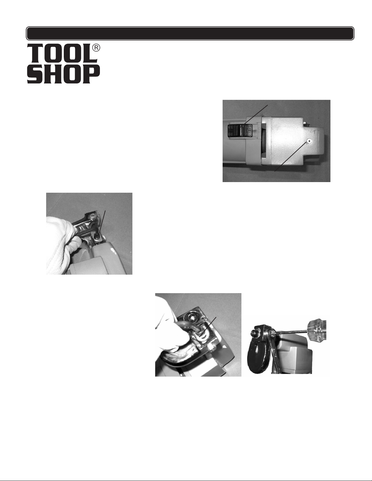
Before each use, plug in the tool, and turn it on to run freely for one minute.
2. Aft e r the toofl has run for one mfinute, turn fit off, and put 3
-4 drops of light machine oil in the oil port on the head of
the tool. (See picture at right.)
3. Also apply a small amount of oil into the space between the
Arbor (13) and the Shaft Sleeve (15).
To remove or replace the blades:
1. Unplug this tool before attempting any maintenance.
2. Remove the Screw and Washers (6,5,4) holding the Upper
Shear Blade (12) & remove it as shown in the photo below
left, using the included Hex Key.
3.Remove the Screw andWashers (6,5,4) holding the Lower Shear Blade
(12) & remove it as in photo below right.
4. To reinstall sharpened blades or new blades, first reinstall the Lower
Shear Blade (2) and tighten it. Then install the Upper Shear Blade (12)
but leave it just loose enough to slide.
5. The Upper Shear Blade (12) has a Adjusting Screw (8) and Screw
(6) that are used to adjust the blade’s position. The Screw (6) should
be loosened with a wrench. Then the Lock Nut (7) should be loosened
and held using a box-end wrench (not included) and the Adjusting
Screw (8) can be adjusted. The Upper Shear Blade (12) should be
adjusted for different material
types or thicknesses.
For sheet steel the formula is:
Gap = Steel Thickness / 5
(as discussed in item 3, page 7)
The gap will be slightly smaller for
rubbery or soft materials.The gap
should be slightly larger for hard
materials.
Power Switch (38)
Oil Port
Screw and Washers (6,5,4)
STEP 1
STEP 2
Adjusting The Upper Shear Blade (12)
Screw and
Washers
(6,5,4)
When the two blades line up with the proper gap, tighten and hold the Adjusting Screw (8) while you
tighten the Lock Nut (7). Then, tighten the Screw (6).
6. Check that the blades will operate properly before use.The machine should always be tested on scrap
material before use on final work material.
7. If you sharpen the blades, maintain the original dimensions of a 12 degree angle on the Upper Shear
Blade (12) with a 8 degree angle across its thickness. Maintain a 4 degree angle on the butt of the
Lower Shear Blade (2) as shown in the illustration below.
5

MAINTENANCE
Replacing Carbon Brushes.
After considerable use, your Electric Metal Shear
may not run as well as usual. If it starts or runs slowly,
makes a grinding noise or will not run at all, the problem
may be worn Carbon Brushes. An extra set of Carbon
Brushes is included with your tool for replacement as
needed.
1. Unplug your tool before beginning work.
2. To examine the condition of the brushes, unscrew
each Brush Cap (43), and remove each Brush (42).
NOTE:Record the position of each carbon brush
as you remove it, so you can replace them in exactly the
same way. Carbon brushes wear into the armature. If they are replaced in a different orientation, they will
have to undergo additional wear before they again fit properly.
3. If the Carbon Brushes (42) are severely worn (less than 1/8” carbon remaining) they should be replaced.
Also, if either brush is cracked or chipped both brushes must be replaced. If they are glazed, but more
than 1/8” in length, the glaze can be removed with a pencil eraser, and the brushes reused. If they are
in good condition and more than 1/8” remains, replace the original brushes in the exact configuration
they were removed.
4. To replace a Carbon Brush (42), insert it into the Brush Holder (41) carbon end first, with the
spring end to the outside. Replace the Brush Cap (43) and tighten it by turning clockwise.
NOTE:When replacing Carbon Brushes (42), do not replace only one brush. Always replace both
carbon brushes at the same time.
5. After replacing the Carbon Brushes (42), let the tool run for 2 minutes before using it.This will allow the
Carbon Brushes (42) to wear into the Armature.
Caution: During use, do not obstruct the motor vents in the Cover (48). Obstruction may cause the
motor to overheat during use, possibly damaging the tool.
Brush Cap (43)
Motor Vents
6

PARTS LIST
SCHEM
!
WARNING Repairs should be made by an authorized repair center.Do not open or
disassemble this power tool. Contact Sharp Group Development Limited at
for questions regarding this power tool.
1-866-915-8626
92148 Pour les questions techniques, appelez-vous s’il vous plaît 1-800-444-3353.Page 13
’
,
Part Description Q’ty
1Tool Rest 1
2Lower Shear Blade (Fixed) 1
3Spring Pin m4 x 30 2
4Plain Washer m6 2
5Spring Washer m6 2
6Socket Head Screw m6 x 12 2
7Lock Nut m5 1
8 Adjusting Flat Head Screw m5 x 16 1
9Spring Washer m4 6
10 Plain Washer m4 4
11 Lock Screw m4 x 15 1
12 Upper Shear Blade 1
13 Arbor 1
14 Straight Pin m8 x 18 1
15 Shaft Sleeve 1
16 Socket Head Screw m5 x 50 2
17 Gear Cover 1
18 Connecting Bar 1
19 Needle Bearing K121610 1
20 Eccentric Shaft 1
21 Straight Key 4 x 8 1
22 Ball Bearing 6201-2Z 1
23 Clip Ring 1
24 Bearing 1
25 Gear 1
26 Self Threading Screw ST3.9 x 19 4
27 Clip Ring 1
28 Intermediate Cover 1
29 Ball Bearing 628-2Z 2
30 Armature 1
Part Description Q’ty
31 Socket Head Screw m4 X 58 2
32 Stator 1
33 Ball Bearing 626-2RS 1
34 Rubber Washer 1
35 Housing 1
36 Socket Head Screw m12 x 30 1
37 Nameplate 1
38 Power Switch 1
39 Drawbar 1
40 Nut m4 2
41 Brush Holder 2
42 Carbon Brush 2
43 Brush Cap 2
44 Support 2
45 Screw ST 3.9 x 9.5 2
46 Switch 1
47 Oil Port 1
48 Cover 1
49 Screw ST3.9 x 16 6
50 Switch Cover 1
51 Switch Holder 1
52 Strain Relief 1
53 Cord Holder 1
54 Power Cord 1
55 Needle Bearing HK071109 1
56 Stem Gear 1
57 Straight Key 1
58 Gear 1
59 Ball Bearing 607-2Z 1
60 Description Plate 1
7
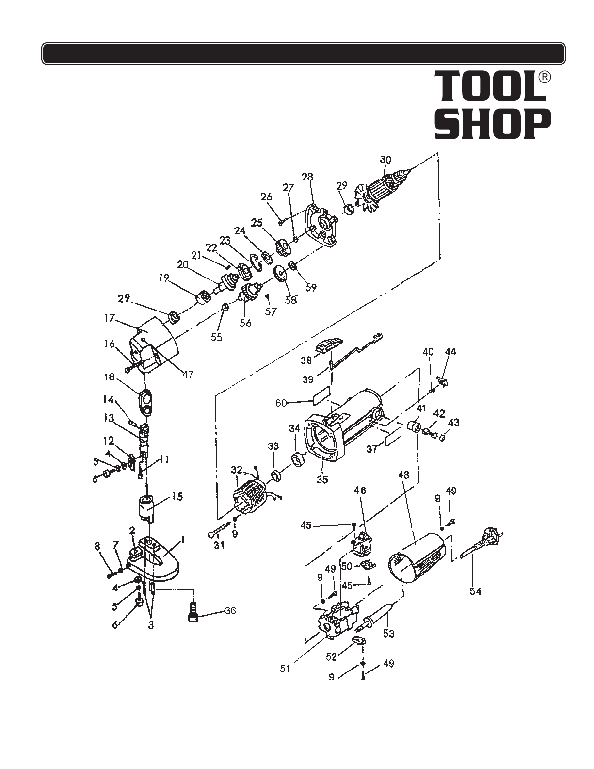
SCHEMATIC DRAWING
8
Table of contents
Other Toolshop Power Tools manuals

Toolshop
Toolshop 241-9*780 User manual

Toolshop
Toolshop 207-4825 User manual

Toolshop
Toolshop 241-9834 User manual

Toolshop
Toolshop 241-9778 User manual

Toolshop
Toolshop 241-9023 User manual

Toolshop
Toolshop 240-2003 User manual

Toolshop
Toolshop 241-9970 User manual

Toolshop
Toolshop 241-8502 User manual

Toolshop
Toolshop 241-9894 User manual


