Top Air TA1200 Installation and maintenance instructions
TA1200/1600
OPERATOR'S MANUAL
and
PARTS LIST
T-TANK SPRAYER
1200 & 1600 GALLON
1200 SPRAYER - 60'/80'/90' BOOMS
1600 SPRAYER - 80'/90'/110'/120'/132' BOOMS
401962
402061

2
Introduction
TABLE OF CONTENTS
SECTION II - OPERATION
PREPARING TRACTOR .............................. 2-2
PREPARING SPRAYER
Inspection ................................................ 2-2
Lubrication ............................................... 2-2
HITCHING TO TRACTOR
Drawbar Connection................................. 2-3
Transport Chain Connection .................... 2-4
Hydraulic Connections ............................ 2-4
Electrical Connections............................. 2-6
TRANSPORTING.......................................... 2-7
BOOM OPERATION
Unfolding Boom ....................................... 2-8
Folding Boom .......................................... 2-9
FILLING SPRAYER
Quick Fill ............................................... 2-10
Tank Mixing ........................................... 2-10
BASIC SPRAYER OPERATION
Initial Settings........................................ 2-11
Secondary Filter Monitoring .................. 2-11
SPRAY TANK RINSING
Rinsing - Complete System .................. 2-12
Rinsing - Boom Only ............................ 2-12
ELECTRICCOMMANDCENTER(Option) ..... 2-13
CHEMICAL INDUCTOR (Option)
Basic Operation..................................... 2-14
Chemical Container and Inductor
Tank Rinsing ........................................ 2-15
FOAM MARKER (Option)
Filling ..................................................... 2-16
Foam Collector Height........................... 2-16
Basic Operation..................................... 2-16
SECTION III - MAINTENANCE
LUBRICATION...............................................3-2
SPRAYER PUMP SET-UP
Load Sensing Closed-Center System ......3-3
Pressure-Compensating Closed-
Center System..........................................3-4
Open-Center System ................................3-4
Sprayer Pump Specifications ...................3-5
HYDRAULIC MANIFOLD SET-UP
Open-Center System ................................3-6
SECTION V - PARTS
Frame, Tongue, Hitch ................................. 5-2
Axle Mounting ............................................. 5-4
Axle Assembly ............................................ 5-5
Hub & Spindle............................................. 5-6
Wheels & Tires ........................................... 5-8
Mast .......................................................... 5-10
Lift Assembly, H-Frame ............................ 5-11
Frame Attachments................................... 5-12
Platform, Railings...................................... 5-14
Ladder, Railing .......................................... 5-16
Gauge Panel ............................................. 5-17
Main Tank ................................................. 5-18
Rinse Tank ................................................ 5-20
Sight Gauge .............................................. 5-22
Strainer...................................................... 5-23
Spray Pump .............................................. 5-24
1600 Spray System .................................. 5-26
1200 Spray System .................................. 5-27
Electric Controls (Option) ......................... 5-30
2-Point Hitch (Option) ............................... 5-32
Inductor Plumbing ..................................... 5-34
Inductor Mounting...................................... 5-36
Decals ....................................................... 5-38
Foam Marker............................................. 5-39
Spray Pump Breakdown ........................... 5-42
Load Sensing Closed-Center System ......3-6
AXLE ADJUSTMENT
Wheel Spacing Combinations ..................3-7
Adjustment Procedure ..............................3-8
WING ADJUSTMENTS
Inner Wing Adjustments ...........................3-9
Outer Wing Level Adjustment ............... 3-12
Wing Tilt Indicator Adjustment.............. 3-13
Wing Tip Breakaway Mechanism .......... 3-13
Twin Link Suspension Adjustment ........ 3-14
FILTERS
Self-Cleaning (Primary) Filter ................ 3-15
Secondary Filter .................................... 3-15
FOAM MARKER SYSTEM
Filter Maintenance ................................. 3-16
Power Box Plumbing Schematic........... 3-16
Foam Marker Winterization ................... 3-17
WINTERIZING SPRAYER.......................... 3-18
TROUBLESHOOTING ................................ 3-19
SCHEMATICS
Sprayer Chemical .................................. 3-20
Hydraulic................................................ 3-21
Electrical.................................................... 3-22
SPRAYER CALIBRATION
Calibrate tractor speed .......................... 3-25
Determine required nozzle size ............ 3-25
Verify nozzle flow .................................. 3-26
SECTION I - SAFETY
GENERAL HAZARD INFORMATION ............1-2
SAFETY DECALS ........................................1-3
GENERAL SAFETY INFORMATION ............1-4
CHEMICAL HAZARDS..................................1-4
SERVICE PLATFORM..................................1-5
ELECTRICAL SAFETY .................................1-5
CLEAN WATER TANK .................................1-5
BEFORE OPERATING OR SERVICING ......1-6
DURING OPERATION ..................................1-6
BEFORE TRANSPORTING ..........................1-7
DURING TRANSPORT..................................1-7
PRESSURIZED OIL ......................................1-8
SECTION IV - SET-UP
Boom Rest Initial Set-Up............................ 4-2

3
Introduction
INTRODUCTION
Product Identification
When ordering parts or when requesting further information or assistance, always give
the following information:
- Machine name
- Model number
- Serial number
Please fill out and retain this portion for your records. The serial number decal is located
at the left front corner of your grain cart.
Purchase date Model Serial no.'s
Dealer City
Dealer Contact Phone
NOTE: The information, specifications, and illustrations in the manual are on the
basis of information available at the time it was written. Due to continuing
improvements in the design and manufacture of Alliance/Top Air products, all
specificationsandinformationcontainedhereinaresubjectto changewithoutnotice.
Foreword
This symbol identifies important safety messages. When you see it, read the
message that follows and be alert to the possibility of personal injury.
Remember, safety instructions stated in this manual are for your protection. Read them
carefully and follow them closely when working around or using this machine.
Read andstudy thismanualcompletelybefore attemptingto operatethis implement. Take
this manual to the field for handy reference when operating, adjusting or servicing your
machine.
When referenced, "Right-Hand" (RH) and "Left-Hand" (LH) side of the machine are
determined by standing behind the machine and facing in the direction of travel.

4
Introduction
NOTES

1-1
Safety
SECTION I
SAFETY
GENERAL HAZARD INFORMATION ............... 1-2
SAFETY DECALS ............................................ 1-3
GENERAL SAFETY INFORMATION ................ 1-4
CHEMICAL HAZARDS..................................... 1-4
SERVICE PLATFORM ..................................... 1-5
ELECTRICAL SAFETY..................................... 1-5
CLEAN WATER TANK..................................... 1-5
BEFORE OPERATING OR SERVICING.......... 1-6
DURING OPERATION ...................................... 1-6
BEFORE TRANSPORTING .............................. 1-7
DURING TRANSPORT ..................................... 1-7
PRESSURIZED OIL.......................................... 1-8

1-2
Safety
Signal Words:
DANGER: Indicatesanimminentlyhazardoussituationthat,ifnot
avoided,willresultindeathorseriousinjury.
WARNING: Indicatesapotentiallyhazardoussituationthat,ifnot
avoided,couldresultindeathorseriousinjury.
CAUTION: Indicatesapotentiallyhazardoussituationthat,ifnot
avoided,mayresultinminorormoderateinjury.
GENERALHAZARD INFORMATION
Most accidents involving product operation, maintenance andrepair arecaused by failure to
observe basic safety rules or precautions. An accident can often be avoided by recognizing
potentiallyhazardous situations before an accident occurs. Aperson must be alert to poten-
tial hazards. This person should also have the necessary training,skills andtools to perform
thesefunctions properly.
REMEMBER:
THINK SAFETY
A CAREFUL OPERATOR IS THE
BEST INSURANCE AGAINST AN
ACCIDENT!
This symbol means
ATTENTION!
BECOMEALERT!
YOURSAFETYISINVOLVED!
Safety precautions and warnings are provided in this manual and on the product. If these
hazard warningsare notheeded, bodilyinjury or death couldoccurtoyou orother persons.
Thesehazardsare typicallyidentified bya "SAFETYALERTSYMBOL",followed bya "SIG-
NALWORD", such as "WARNING", as shown below:
Improper operation, maintenance or repair of this machine can be
dangerous and could result in injury or death. Do not operate or perform
any maintenance or repair on this machine until you have read and
understood all applicable safety, operation, maintenance, or repair
information.
1-3
Safety
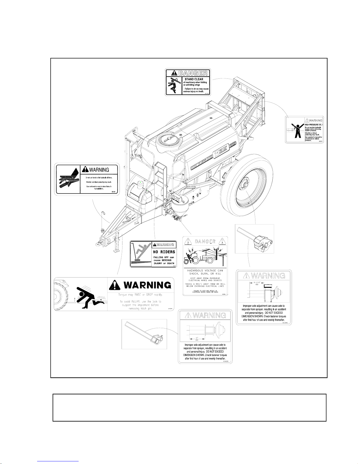
SAFETY DECALS
•401956
IMPORTANT
Replacelost,damaged, painted,orunreadabledecalsimmediately. If partsthathave decalsarereplaced,
also make sure to install new decals. These decals inform and remind the operator with operational
informationandsafetymessages.
•Revised011405

1-4
Safety
GENERALSAFETY
INFORMATION
•Donotallowchildrentoplayonor
near,andpreventinexperiencedor
unauthorizedpersonsfromoperating
thisequipment.
•Hitchsprayertoatractortostabilize
unitpriortofillingwithliquid,unfolding
boom orattachingand/orremoving
majorcomponents.
•Donotoperateequipmentuntilall
shields,coversandguardsare
installed.
•Keephands,feetandclothingaway
frommovingparts. Donotwear
loose-fittingclothes,astheymaycatch
onmovingparts.
•Inspectwhenfirstdeliveredand
regularlythereafterforanyloosebolts
and/orconnections.
•Donotstandbetweenthesprayerand
tractorwhenhitching. Alwaysengage
parkingbrakeandstopenginebefore
insertinghitchpin.
•Thissprayerisintendedtoonlyspray
agriculturalchemicals. Attemptingto
sprayotherliquidsmaycause
equipmentdamageandintroduce
unexpectedpersonalhazards.
CHEMICALHAZARDS
•Alwayswearpersonalprotective
equipmentwhenworkingwithornear
chemicals. Thisequipmentincludes,
butisnotlimitedto:protective
eyewear,gloves,shoes,socks,long-
sleevedshirtandlongpants.
Additionalprotectionmayberequired
formanytypesofchemicals.
•Spraytankmaycontainresidualtoxic
chemicals. DONOTENTERSPRAY
TANKFORANYREASONWITHOUT
WEARINGPROPERVENTILATING
EQUIPMENT. Failuretodo somay
resultinsuffocationanddeath.
•Seekandreceivechemicalproduct
trainingpriortousingagricultural
chemicals.
•Readandunderstandtheentirelabel
ofeverychemicalbeingappliedwith
thissprayer.
•Avoidbreathingspraymistorvapor.
•Washhandsbeforeeating,drinking,
chewinggum,orusingthetoilet.
•Removeclothingimmediatelyif
chemicalspenetrateclothingand
contactskin. Washthoroughlyandput
oncleanclothing.
•Disposeofunusedchemicalin
accordancewithchemicallabel
directionsandlocal/national
regulations.
1-5
Safety
SERVICEPLATFORM
•Mountanddismountthesprayeronly
wherestepsand/orhandholdsare
provided.
•Facethesprayerwhenmountingand
dismounting.
•Donotallowridersonsprayer.
•Inspect,andwhennecessary,clean
andhaverepairsmade tostepsand
handholdsbeforemountingand
dismounting.
•Maintainathree-pointcontact(two
feetand onehandoronefoot andtwo
hands)withthestepsandthe
handholds.
•Nevergetonoroffamovingsprayer.
•Neverjumpoffthesprayer.
•Donottrytoclimbonoroffthe
sprayerwhencarryingtoolsor
supplies.
ELECTRICALSAFETY
•Theelectricalsystemofthissprayer
is designed to operate on 12 volt DC
poweronly.
•Neveroperatethesprayerwitha
damagedelectricalcord. Disconnect
electrical power if a cord is damaged.
•Alwaysdisconnectpowerbefore
attemptinganyelectricalrepair.
•Disassemblyorattemptedrepairs, if
accomplishedincorrectly,cancreate
electricalshockand/orshorthazards.
Onlyqualifiedpersonnelshould
performrepairservice.
•Neverattempttobypass fuses. Do
notreplaceoriginalfuseswithhigher
amperagefuses. Ifafuserepeatedly
fails,ashorthazardmayexist.
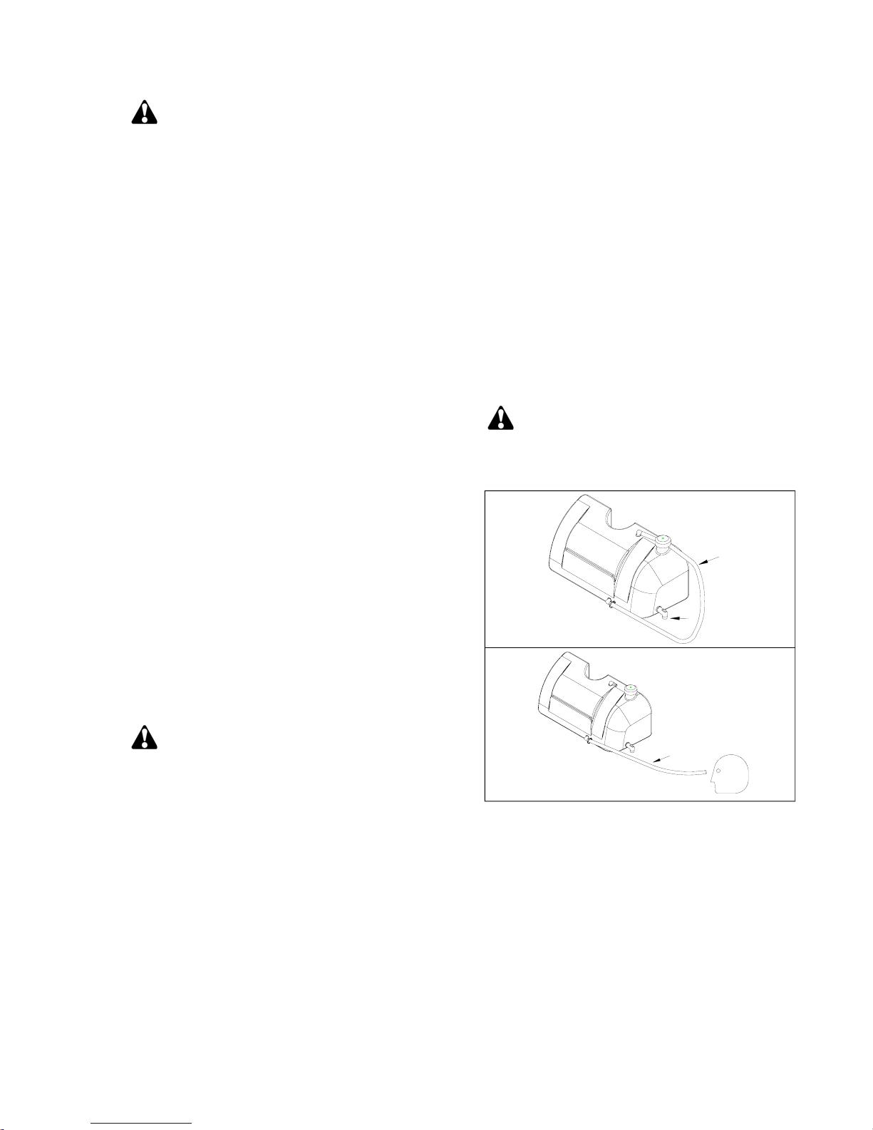
CLEAN WATER TANK
•Acleanwatertank isprovided as
standardequipment. Itisequipped
withaspigotforgeneralwashing,and
ahoseforemergencyeyewashing.
•Alwayskeepcleanwaterintank.
•Foremergencyeyewash,pullhoseoff
ofthetopfittingandflushaffected
area.
400935
HOSE
EYE WASH
EYE WASH
HOSE
SPIGOT

1-6
Safety
BEFOREOPERATING
OR SERVICING
•Securedrawbarpinwithalocking
deviceandlocktractordrawbarin
centeredposition. Ensurethatthe
tractordrawbarhassufficientstrength
tosupportboththedraftandvertical
tongueloadofafully-loadedsprayer.
•Lowerorsecurelyblockupelevated
componentsbeforeservicingorwhen
leavingtheequipment. Neverwork
underanimplementunlessitis
securelysupported.
•Turntractorpoweroffandremovekey
fromignitionbeforeservicingor
adjustingequipment.
•Whenoperatingsprayersonsidehill
conditions,itisrecommendedthatthe
wheel spacing be set as wide as
possibleforstability.
•Verifythatallguardsandshieldsare
inplace.
•Hitchsprayertotractorand clearall
personnelfromthesurroundingarea
beforefoldingandunfoldingwings.
•Become aware ofand avoid all
obstaclesandhazardsinthepathof
theequipment,suchaspowerlines,
ditches,etc.
•Residualpressuremayexistin
sprayerplumbingevenwhenunitis
notinuse. Removepressurebefore
servicinganyplumbing.
•Ensurethatallapplicablesafety
decalsareinstalledandlegible.
DURINGOPERATION
•Donotallowanyonetorideonthe
equipment. Neverdismountfroma
movingtractor. Severeinjuryordeath
canoccurfrombeingrunoverbythe
implement.
•Regulatespeedtofieldconditions.
Maintaincompletecontrolatalltimes.
•Neverlubricateequipmentwhenin
operation.
•Become awareoftheoperating width
ofthisimplement. Useextremecare
whenoperatingclosetoditches,
fences,powerlines,oronhillsides.
•Donotleaveequipmentunattended
withenginerunning.

1-7
Safety
BEFORE
TRANSPORTING
•Thissprayerisnotequippedwith
brakes. Ensurethatthetowingvehicle
hasadequateweightandbraking
capacitytotowthisimplement.
•Securetransportchaintotractorchain
supportbeforetransporting. Adjust
thechainlengthasnecessaryto
eliminateexcessiveslack,while
preventingbindingduringtightturns.
•Verifythatallappropriatelightingand
reflectorsareinstalledandcomply
withstateandlocallawsgoverning
highwaysafety.
DURINGTRANSPORT
•Usegoodjudgmentwhentransporting
equipmentonhighways. Regulate
speedtoroadconditionsand
maintaincompletecontrol.
•Maximumspeedofsprayershould
neverexceed25mph.
•Itisprobablethatthisimplementis
taller,widerandlongerthanthetowing
vehicle. Becomeawareof andavoid
allobstaclesandhazardsinthetravel
pathoftheequipment,suchaspower
lines,ditches,etc.
•Slowdownbeforemakingsharpturns
toavoidtipping. Driveslowlyover
roughgroundandsideslopes.
•Useexceptionalcarewhenoperating
sprayerequippedwithsingletiresand
setatnarrowwheelspacing. The
possibilityoftippingoverduringturns
ortravelonroughroadsisincreased
undertheseconditions

1-8
Safety
PRESSURIZEDOIL
•Alwaysuse a boardor cardboard
whencheckingforapressurizedoil
leak. Escapingfluidunderpressure,
evenapinhole-sizedleak,can
penetrateskin,causingseriousinjury,
andpossibledeath. Iffluidisinjected
intoyourskin,itmustbetreated
immediatelybyadoctorfamiliarwith
thistypeofinjury.
•Neverloosenorremoveanyhydraulic
fittingwithoutfirstverifyingthatallfluid
pressurehasbeenrelieved. Failure
todosomayresultinunintended
movementofalloraportionofthe
equipment,possiblycausingsevere
injuryordeathduetocrushingor
cutting. Injurymayalsooccurfrom
contactwithoilunderpressurethat
mayescapeduringfittingremoval.
• Accumulatorsusedinthis hydraulic
systemcanretainfluidunderpressure
evenaftertractorhydraulicvalveis
placedinFLOAT. Removeresidual
pressurefromwingtiltandmainlift
accumulatorsbyholdingwingtiltand
mainliftswitchesinDOWNposition
foratleast20secondsaftercylinders
havestoppedmoving.
•Safelyrelieveallfluidpressurefrom
hydraulichosesbeforedisconnecting
hydrauliccouplingsfromtractor.
•Donotbendorstrikehigh-pressure
lines. Donotinstall bentordamaged
tubesorhoses.
•Checkhydraulichosesandtubes
carefully. Replacecomponentsas
necessaryifanyofthefollowing
conditionsarefound:
-Endfittingsdamagedorleaking.
-Outercoveringchafedorcutand
wirereinforcingexposed.
-Outercoveringballooninglocally.
-Evidenceofkinkingorcrushingof
theflexiblepartofahose.
-Armoringembeddedintheouter
cover.
-Endfittingsdisplaced.
•Repair all oil leaks. Leaks can cause
fires,personalinjury,and
environmentaldamage.
•Routehosesandlinescarefullyto
preventprematurefailuredueto
kinkingandrubbingagainstother
parts. Makesurethatall clamps,
guardsandshieldsareinstalled
correctly.
•Revised011405

2-1
Operation
SECTION II
OPERATION
PREPARING TRACTOR.......................................... 2-2
PREPARING SPRAYER
Inspection............................................................ 2-2
Lubrication .......................................................... 2-2
HITCHING TO TRACTOR
Drawbar Connection........................................... 2-3
Transport Chain Connection............................... 2-4
Hydraulic Connections........................................ 2-4
Electrical Connections ........................................ 2-6
TRANSPORTING...................................................... 2-7
BOOM OPERATION ................................................ 2-8
Unfolding Boom.................................................. 2-8
Folding Boom ..................................................... 2-9
FILLING SPRAYER
Quick Fill........................................................... 2-10
Tank Mixing ...................................................... 2-10
BASIC SPRAYER OPERATION
Initial Settings ................................................... 2-11
Secondary Filter Monitoring ............................. 2-11
SPRAY TANK RINSING
Rinsing - Complete System ............................. 2-12
Rinsing - Boom Only ........................................ 2-12
ELECTRIC COMMAND CENTER (OPTION) ........ 2-13
CHEMICAL INDUCTOR (OPTION)
Basic Operation................................................ 2-14
Chemical Container & Tank Rinsing................ 2-15
FOAM MARKER (OPTION)
Filling ................................................................ 2-16
Foam Collector Height ..................................... 2-16
Basic Operation................................................ 2-16

2-2
Operation
Before operatingsprayer, readthe tractor
operator’smanual andgainan
understanding of its safe methods of
operation.
Check the tractor brakes and warning
lights. Make sure they are in proper
working order.
Check the tractor hydraulic oil reservoir
and add oil if needed.
Verify that the tractor is adequately
ballasted for drawbar operation at the
anticipateddraftand verticaltongue load.
Vertical tongue loadof aloaded sprayer
(with boomsfolded totransport position)
isapproximately 5000lbs. Ensure that
thetractor’sdrawbarhassufficient
strength to support thisload.
Ifpossible,adjustthetractordrawbar
verticallyso thetop sideof thedrawbar is
atleast 18inchesfromtheground.
Alternately, the sprayer hitch may be
adjusted vertically by choosing other
mounting holes provided.
Onsprayersequippedwithadrawbar-
stylehitch,raiseandsecurealltractor3-
point hitchlinkage to prevent interference
with the implement tongue and hydraulic
hosesduringturning.
Extratractorballast may berequired for
usewithsprayers equippedwith2-point
style hitch option. Shim or adjust tractor
3-point hitchto remove all sidesway prior
tooperation.
•Inspection
Performtheservicechecksasoutlined
below. Repair or replace any damaged
orworn parts before operating.
Boom Rest Set-up: Refer to page 4-2
for initialboomrestset-up procedures.
Hardware: Check for loose bolts and
nuts, and tighten as needed. Check
again after the first half-day of operation.
Pivot Pins: Check that all pins are in
place and in good condition. Replace
any worn, damaged, or missing pins.
Hydraulic System: Check all hoses and
cylinders for signs of leakage. Hoses
should not be kinked, twisted or rubbing
againstsharpedges. Rerouteor repair
hoses as necessary. Refer to SAFETY
section for additional information on
safe repair and inspection of hydraulic
components.
Tires/Wheels: Check tire pressures and
maintain at recommended values listed
in the MAINTENANCE section of this
manual. Maintain 500 lb-ft. torque for
the 7/8" wheel lug bolts.
CAUTION: Frequentlycheck the
torque ofall wheel lug nuts, particularly
during the initial transport and operation
ofthisimplement. Ifa lugboltorstud
becomes loose,this mayresult inthe loss
of a wheel and subsequent loss of control
ofthe tractor and/or sprayer.
PREPARING TRACTOR PREPARING SPRAYER
•Lubrication
Lubricate the sprayer as outlined in the
MAINTENANCE SECTION of this
manual.
•Revised011405

2-3
Operation
WARNING: Do not stand between
the implement and tractor when
hitching. Serious or fatal injury can
occur due to crushing hazard from
limited clearance between tractor and
implement. Always engage parking
brake and stop engine before inserting
hitch pin.
Connect the drawbar hitch only to the
tractordrawbar. Donotattemptto hitchto
any other location on the tractor.
Thesprayer isequipped standardwith a
clevishitch,whichrequiresa1 ¼”
drawbar pin. This hitch can be converted
to a single tang style by unbolting and
removingtheclevis. Whenusedasa
singletang style,a 1½” diameter
drawbarpin mustbe used.
NOTE: The useof a smaller diameter
hitchpin will result in additional clearance
between the implement hitch and pin.
Thisadditional clearancemay cause
acceleratedpin andhitch wear,alongwith
morepronouncedjoltingfromthesprayer
duringoperation.
Afterinserting drawbar pin, secure with a
locking device to helpprevent uncoupling
during use.
•2-Point Hitch (Optional)
Theoptional 2-pointhitchis compatible
with Cat III-N, CATIII andCATIV-N
hitches. Verifyhitchpinsize compatibility
priorto hitching.
After couplingto tractor,raisesprayer
tonguehigh enough to allowhitch stands
to beremoved. Reinsertstandsinto the
topof thereceiver tubesfor storage
duringsprayeruse. Maintainthetractor
hitch at aheight that allows the sprayer to
bereasonablylevel.
CAUTION: If a 3-point hitch quick-
couplerisused,alwaysverify thatthepin
retaining latches are fully engaged before
moving sprayer. Failureto dosocould
result inlossofsprayercontroldueto
hitchuncoupling.
401931
HITCHING TO TRACTOR
•Drawbar Connection
Verify and/or adjust the sprayer hitch
height before coupling to the tractor. The
sprayer hitch isadjusted by unbolting the
hitch and reinstalling in a different set of
holes provided.
NOTE: Thesprayermustbe relatively
level inorder forthetankvolume indicator
toreadaccurately.
•Revised011405
401931
Stands
Receiver Tubes
2-4
Operation
NOTE: The sprayer pumpis hydraulically
driven, and needs tobe configured
correctly to match the type of hydraulic
systemon thetractor(closedcenter, open
center,loadsensing,etc.). Failureto
configure the pumpcorrectly may
permanentlydamage the pump through
over-speeding. Refertothe
MAINTENANCE SECTION of this
manual for guidelines on configuring the
sprayer pump.
Connecthoses fromthe sprayerpump to
a tractorselective controlvalve (SCV)
circuit. The pump inlet (marked PUMP
PRESSURE) should be connected to
the RETRACT port and the pump outlet
(marked PUMP RETURN) to a low
pressure return port at the tractor
(recommended) orto theEXTENDport.
•Revised011405
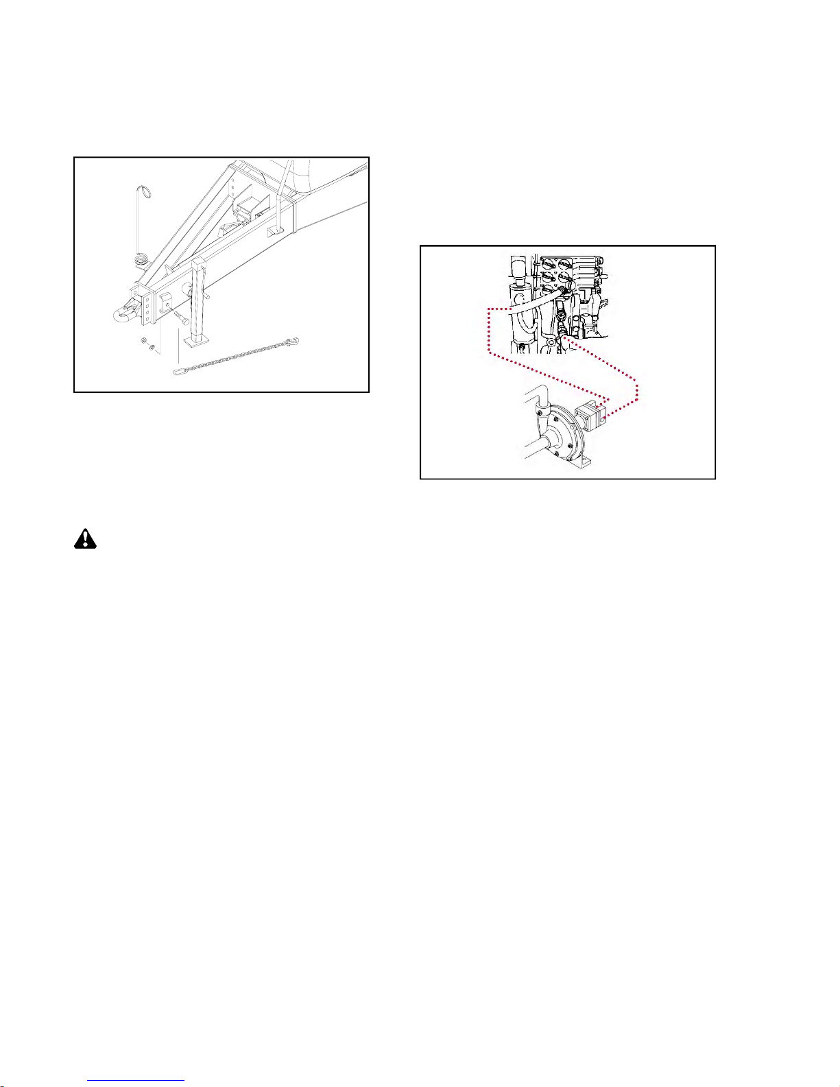
•Transport Chain Connection
(Drawbar Style Hitch Only)
Tractor must be equipped with a
transport chain support. Attach chain in
manner illustrated. Adjust the chain
length as necessary to eliminate
excessive slack, while preventing
binding during tight turns.
CAUTION: Always use a properly-
sizedtransportchain between sprayer
andtractor. Failuretousetransportchain
could result in personal injury or property
damage ifimplement andtractor become
disengagedduringoperation.
401930
•Hydraulic Connections
After cleaning hydraulic hose couplers,
connect to tractor hydraulic circuits as
follows:
Sprayer Pump Hydraulics

2-5
Operation
hydraulic circuit. When the circuit is
energized, oil will circulate constantly
through the sprayer hydraulic valve.
Because of this, it is important to
minimize the flow through this circuit.
Adjust the tractor SCV flow control to
the lowest setting that still allows the
boom functions to operate at an
acceptable speed. Doing so will keep
any oil heating to a minimum, and allow
other SCV circuits to operate normally.
Note: Ifthe SCVcontrol leverkicksout
prior to actuating any switch on the
boom control box, the most likely reason
is excessive hydraulic pressure. Try
reducing the tractor’s flow control
setting. Also, excessive pressure can
also occur if the hydraulic valve has
been modified for use with power
beyond systems. In thisinstance, attach
to the three power beyond couplers on the
tractor, or change thehydraulic valve
attachtothethreepowerbeyondcouplers
onthe tractor, or changethe hydraulic
valve setupfor usewithan SCV circuit.
Refer tothe MAINTENANCESECTION
for valvesetup information.
Toprotectthesprayerpumpfrom
damage due to excessive speed, adjust
circuit flow to minimum setting prior to
operating circuit for the first time. When
in operation, adjust flow per instructions
listed under the “Basic Sprayer Settings”
heading in this section.
IMPORTANT: Never operate sprayer
pump dry, or with PUMP INLET
SELECTOR valve closed. Pump
damage may result.
Boom Hydraulics
CAUTION: Do not unfold or fold
boom withouthitching tothe tractor.
Thewing-foldhydraulicsystemonthis
sprayeris configuredto connectto a
tractorSCV valve,but canalsobe
modified tooperate with power beyond
circuitsoftractorswitha load-sensing
hydraulic system(Referto the
MAINTENANCE SECTION for
information onconvertingtoa power
beyond circuit).
Connect the hose marked BOOM
PRESSURE to the EXTEND port of one
of thetractor SCVcircuits, andthe hose
marked BOOM RETURN to the
RETRACT portofthesamecircuit.
802967
Placethetractor SCVcontrol leverin the
EXTENDposition toenergize the

2-6
Operation
•Electrical connections
Thisimplement isequipped witha 7-pin
SAEconnectorplug,whichwill connect
withthereceptaclefoundonmostnew
tractors on the market today. If your
tractordoesnothavethistypeof
receptacle, an SAE J-S60A 7-pin socket
canbe purchasedfromyourTopAir
dealer (Partnumber 92824).
Thewiringschematicforthissprayer
complies withANSI/ASAE Standard
S279/SAE J137. Although most new
tractorsconformtothisstandard,many
older tractors (notably John Deere) can
have aslightlydifferentelectrical function
thanstandard. Becauseofthis,always
verify correct electrical function before
using this sprayer. Awiringschematic is
provided inthe MAINTENANCE
SECTION of this manual.
•Revised011405
Beforedisconnectinghosesfromthe
tractor,relievepressurefromthelinesby
placing the circuit in “float” while the
tractor engine is running. Shutoff engine
andapply parkingbrake before
disconnecting hoses.
NOTE: Accumulatorsusedinthishy-
draulic systemcan retain fluid under
pressure evenafter tractor hydraulic valve
is placed inFLOAT. Remove residual
pressure fromwing tiltandmainlift accu-
mulatorsbyholdingwingtiltandmainlift
switches inDOWN positionfor atleast 20
seconds after cylindershave stopped
moving.
NOTE: Afterinitial set-upor replacement
of any hydraulic component onthe
sprayer,air mustbe removedfromthe
wing-fold hydraulic systempriortoitsfirst
use. Failureto doso mayresultin
damage toboomcomponents due to
rapidmovement.
•Hydraulic Connections
(cont.)

2-7
Operation
WARNING: Use exceptional care
when operating sprayer equipped
with single tires and set at narrow
wheel spacing. The possibility of
tipping over during turns or travel on
rough roads is increased under these
conditions.
Usegoodjudgmentwhentransporting
equipmentonhighways. Regulatespeed
toroadconditionsandmaintain complete
control.
Itisprobablethatthisimplementistaller,
wider and longer than the towing tractor.
Become aware ofand avoid all obstacles
and hazards in thetravel path of the
equipment,suchas powerlines,ditches,
etc.
Slowdown beforemaking sharpturnsto
avoid tipping. Drive slowly over rough
ground and side slopes.
401962
TRANSPORTING
CAUTION: This implement is not
equipped with brakes. Ensure that the
towing vehicle has adequate weight and
brakingcapacityto towthis implement.
NOTE: It isstronglyrecommendedtouse
the 120”wheel spacing while running
single tires.
Asa guideline,thetowingvehicleshould
besizedsuchthat the loadedsprayer
does notweigh over1.5 times the towing
vehicle weight. Maximumspeedof
sprayershouldnotexceed25m.p.h..
Secure drawbar pin with a locking
device and lock tractor drawbar in
centered position.
Secure safety chain to tractor chain
support before transporting.
2-8
Operation
BOOM OPERATION
WARNING: Keep all personnel a
safe distance away from the sprayer
when unfolding or folding the boom.
Personal injury can result from
impact with boom.
WARNING: Perform boom
unfolding and folding operations only
in areas with adequate height, width
and length clearances. In particular,
be mindful of location of overhead
power lines. Failure to do so can
result in personal injury and property
damage.
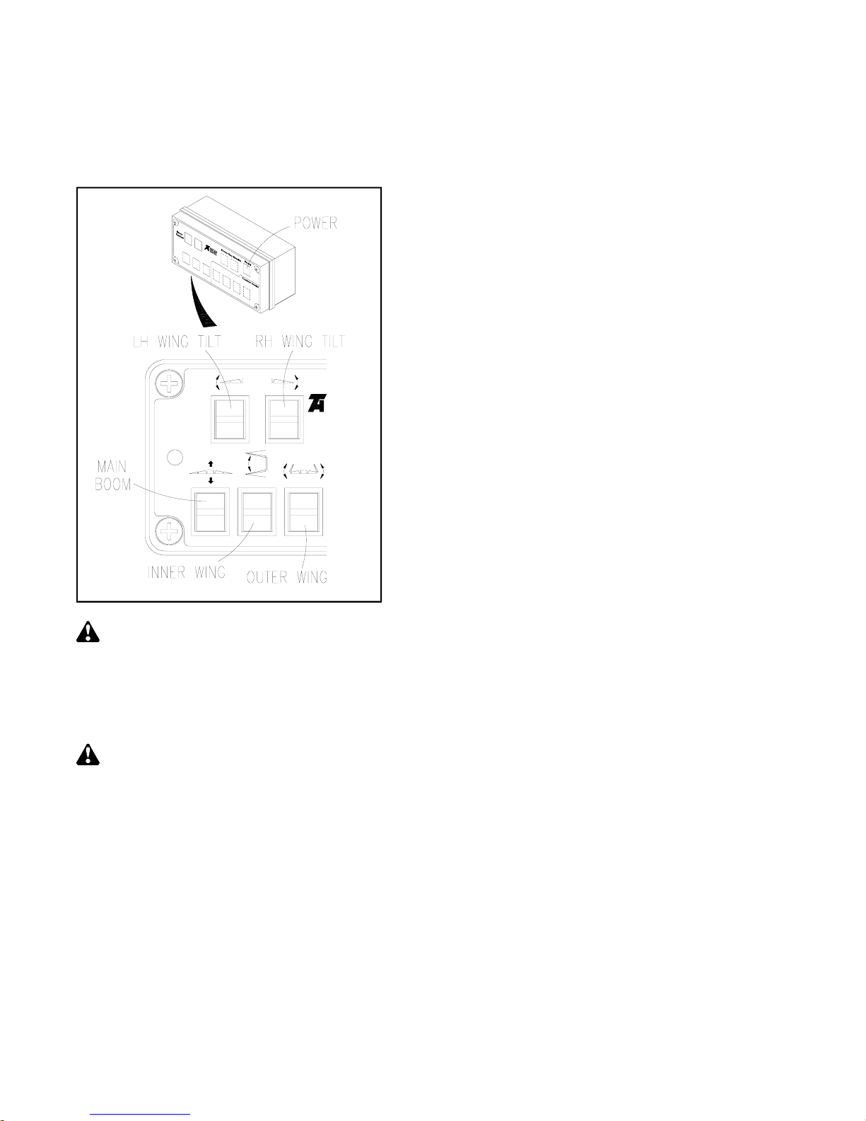
1. Press top of ON/OFF switch to turn
power on. (Red LED lamp on rocker
switch should illuminate. Green LED
lamp is provided to indicate circuit
continuity whenever any other switch
is pressed.)
2. Press and hold MAIN BOOM switch
in <RAISE> position until boom is
fully raised. This ensures that the
transport latch is not supporting the
weight of the boom.
3. Press and hold RH WING TILT and
LH WING TILT switches in <UP>
position until wings are fully tilted
upward. Note: Wing tilt function
may require several seconds of use
before wings begin to move.
4. Press and hold INNER WING switch
in <EXTEND> position until wings
are fully extended and wing locks are
engaged on lock pins.
5. Momentarily press WING TILT
switches either <UP> or <DOWN>
as required to approximately level
the wings horizontally.
6. Press and hold OUTER WING
switch in <EXTEND> position until
outer wings are fully extended.
7. Momentarily press WING TILT
switches either <UP> or <DOWN>
as required to level the wings
horizontally. (Observe the tilt
indicators located near the tilt
cylinders to assist with leveling the
wings.)
8. Press and hold MAIN BOOM switch
in <LOWER> position until boom is
at desired spray height.
IMPORTANT: Never unfold the unit
withoutattachingtotractorfirst. For
properboomsuspensionoperation,do
notoperateboomin thefullylowered
position. Theminimumsprayheightis
attained by lowering the boomfully, then
raisingit approximately 4 inches to permit
adequatesuspensiontravel.
401965
BOOM
CONTROL
RETRACT
EXTEND
RETRACT
EXTEND
•Unfolding Boom
•Revised011405
This manual suits for next models
1
Table of contents


