Uni-ram UG1000 Series User manual

Oct.1, 2003 Rev.A
OPERATING MANUAL
SPRAY GUN CLEANERS
UG1000 - UG3000 SERIES
PATENTS
USA 4,788,836 CANADA
USA 5,213,117 ENGLAND
EUROPE 0300248 ITALY
SWEDEN 0300248 GERMANY
FRANCE 8110528.0 JAPAN
UNI-RAM CORPORATION • ONTARIO • CANADA

MANUAL - SPRAY GUN CLEANERS - UG1000-3000 SERIES
2
CONTENTS
INTRODUCTION . . . . . . . . . . . . . . . . . . . . . . . . . . . . . . . . . . . . . . . . . . . . . . . . . . . . . . . . . . . . . .3
CAUTIONS AND WARNINGS . . . . . . . . . . . . . . . . . . . . . . . . . . . . . . . . . . . . . . . . . . . . . . . . . . . .3
FEATURES AND STRUCTURE OF SPRAY GUN CLEANERS
FEATURES BY MODEL . . . . . . . . . . . . . . . . . . . . . . . . . . . . . . . . . . . . . . . . . . . . . . . . . .3
STRUCTURE OF SPRAY GUN CLEANERS . . . . . . . . . . . . . . . . . . . . . . . . . . . . . . . . . .4
SETUP
INSPECTION . . . . . . . . . . . . . . . . . . . . . . . . . . . . . . . . . . . . . . . . . . . . . . . . . . . . . . . . . . .5
LOCATION . . . . . . . . . . . . . . . . . . . . . . . . . . . . . . . . . . . . . . . . . . . . . . . . . . . . . . . . . . . . .5
LEVELING, VENT AND AIR SUPPLY . . . . . . . . . . . . . . . . . . . . . . . . . . . . . . . . . . . . . . . .5
SOLVENT SELECTION . . . . . . . . . . . . . . . . . . . . . . . . . . . . . . . . . . . . . . . . . . . . . . . . . .5
SOLVENT PAIL SETUP . . . . . . . . . . . . . . . . . . . . . . . . . . . . . . . . . . . . . . . . . . . . . . . . . . .6
GROUND WIRE INSTALLATION . . . . . . . . . . . . . . . . . . . . . . . . . . . . . . . . . . . . . . . . . . .6
OPERATION
PRE - CLEAN . . . . . . . . . . . . . . . . . . . . . . . . . . . . . . . . . . . . . . . . . . . . . . . . . . . . . . . . . .6
CLEANING SPRAY GUNS AND CUPS . . . . . . . . . . . . . . . . . . . . . . . . . . . . . . . . . . . . . .6
AFTER CLEANING . . . . . . . . . . . . . . . . . . . . . . . . . . . . . . . . . . . . . . . . . . . . . . . . . . . . . .7
DAILY MAINTENANCE
FILTER PADS AND SCREEN . . . . . . . . . . . . . . . . . . . . . . . . . . . . . . . . . . . . . . . . . . . . . .8
REPLACING SOLVENT . . . . . . . . . . . . . . . . . . . . . . . . . . . . . . . . . . . . . . . . . . . . . . . . . .8
TROUBLESHOOTING CHART . . . . . . . . . . . . . . . . . . . . . . . . . . . . . . . . . . . . . . . . . . . . . . . . . . .9
TROUBLESHOOTING PROCEDURES . . . . . . . . . . . . . . . . . . . . . . . . . . . . . . . . . . . . . . . . . . . .11
FLOW DIAGRAMS . . . . . . . . . . . . . . . . . . . . . . . . . . . . . . . . . . . . . . . . . . . . . . . . . . . . . . . . . . . .13
REPLACEMENT PARTS . . . . . . . . . . . . . . . . . . . . . . . . . . . . . . . . . . . . . . . . . . . . . . . . . . . . . . .14
ACCESSORIES AND CONSUMABLES . . . . . . . . . . . . . . . . . . . . . . . . . . . . . . . . . . . . . . . . . . . .15
WARRANTY
EXTENDED WARRANTIES For North American Customers . . . . . . . . . . . . . . . . . . . . .15
FULL PRODUCT WARRANTY . . . . . . . . . . . . . . . . . . . . . . . . . . . . . . . . . . . . . . . . . . . .16

3
INTRODUCTION
Uni-ram holds many patents on designs used in its innovative products. Every machine is rigorously
tested for compliance with stringent Quality Assurance standards. Follow the directions in this manual
under Setup, Operation and Maintenance in order to operate this machine safely and effectively. Not
following these instruction can lead to malfunction or damage to the machine. Follow directions under
the section below, Cautions and Warnings and on labels attached to the machine. Ensure that the
manual is readily available for the operator at all times. If you have any questions about the operation
of this machine, call your distributor or a Uni-Ram Service Engineer.
CAUTIONS AND
WARNINGS
• Always disconnect this machine from power sources before performing maintenance
• Do not smoke or use near open flames, sparks or heat.
• Ground pails and cabinet using supplied grounding wires
FEATURES AND STRUCTURE OF SPRAY GUN CLEANERS
FEATURES BY MODEL
Note: V in model number indicates fume venting.
MANUAL - SPRAY GUN CLEANERS - UG1000-3000 SERIES
North America:
Uni-ram Technical Service
1-800-417- 9133
Other Continents:
Contact Your Supplier
3
MODEL SERIES UG1000D
UG2000D/
UG3000D
UG3000DA
GUNS CLEANED 122
NO. OF JETS 91414
AUTOMATIC WASH
•••
AUTOMATIC AIR FLUSH
•
TANK MATERIAL
LID MATERIAL
SHIP SIZE
SHIP WEIGHT
Stainless Steel
54 LB / 25 KG
19 " W X 19 " W X 42" H
Stainless Steel

MANUAL - SPRAY GUN CLEANERS - UG1000-3000 SERIES
4
Automatic Wash Timer
Air Flush Button
(UG3000DA only)
Tank Lid
Cleaning Tank
STRUCTURE OF SPRAY GUN CLEANERS
Access Door
(UG3000D and
UG3000DA only)
Ground Wire

5
SETUP
INSPECTION
• Inspect the shipping carton for signs of damage. It is your responsibility to report damage to the
transport company. Uni-ram Corporation does not accept responsibility for shipping damage
once the machine has left our warehouse. Keep the packaging materials until you are sure the
machine has not been damaged during shipping.
• Remove the machine from the carton by opening the bottom flaps and sliding the carton up over
the machine.
• Make sure the bag of accessories contains the following:
• Manual
• Trigger Lock Springs, 3 pieces (Part No. 120-350, Pkg of 3)
• Air Inlet Cap, 3 pieces (Part No. 100-611)
• Moisture Filter (Part No. 10-220)
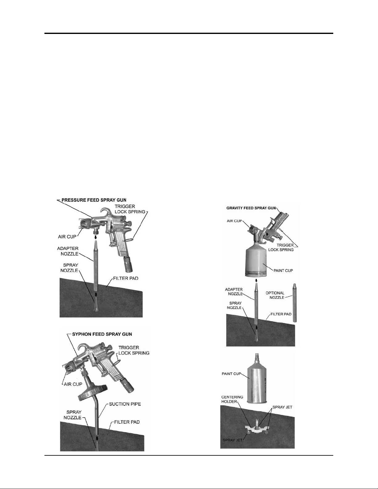
• Nozzle Adapters, 1 each of 2 kinds (Part No. 110-430 and 110-430L1P)
(Part number for optional mini adapter is 110-430MJP)
If any item is missing, contact your supplier.
LOCATION
Position in a well-ventilated area away from sparks, heat and open flames.
LEVELING, VENT AND AIR SUPPLY
• Level the machine using the adjustable legs.
• Attach a vent hose (not supplied) to the vent outlet on top of the
machine. The duct system must not be under continuous vacuum.
• Remove the cover on the "Air Input" (right side of machine) and
screw in the Air Filter Assembly.
• Attach an air supply adapter (not supplied) to Air Filter.
The air supply pressure must be at least 85 PSI and
the air must be free from contaminants such as water, dust, rust, tar,
grease etc.
To prevent damage to the Diaphragm Pump an internal Air Pressure
Regulator has been installed to limit the air pressure to precisely 85 PSI. Do not install a sec-
ond air pressure regulator or use a pressure set below 85 PSI.
See the section, Daily Maintenance, for proper maintenance of the Air Filter Assembly.
MANUAL - SPRAY GUN CLEANERS - UG1000-3000 SERIES

MANUAL - SPRAY GUN CLEANERS - UG1000-3000 SERIES
6
SOLVENT SELECTION
The adhesion quality of automotive paint has dramatically improved in recent years. The choice of sol-
vent is critical. Only use good quality solvent that is formulated for your paint and intended for use
with automatic spray guns cleaners.
SOLVENT PAIL SETUP
• Open the door to the base cabinet
• Move the Drain Valve handle to the "closed" (horizontal) position if it is not already there. See
picture on right.
• One 5-Gal (19 L) pail of solvent is required. Place the pail in front of the machine.
• Disconnect the Suction Pipe from the Drain Valve by pushing the gray button and bring pipe
outside of the cabinet.
• Move the pail into the cabinet and re-connect the Suction Pipe to the Drain Valve. Insert suction
pipe into the pail.
GROUND WIRE INSTALLATION
• Three ground wires are provided to discharge static electricity. To work properly, all three must
be installed correctly. Connect the two wires inside the cabinet to the pails, one to each, and the
wire on the outside back of the cabinet to an external grounded object.
Drain Valve

7
MANUAL - SPRAY GUN CLEANERS - UG1000-3000 SERIES
OPERATION
PRE - CLEAN
• Disconnect the spray gun from the air hose. Pour paint from the cup (when present) into a 5 gal-
lon pail (not supplied).
• Rinse cup with solvent and pour into the same
5 gallon pail for later disposal or recycling.
CLEANING SPRAY GUNS AND CUPS
• Loosen the air cap of the spray gun two full turns.
• Lock the trigger in the open position with the Trigger Lock Spring.
• Plug air inlet of spray gun with cap to prevent solvent from entering passage. Caps are supplied in
the accessory kit.
SPRAY GUNS AND CUPS
• Place spray guns facing corner jets. Placement depends on type of spray gun. See pictures.
Place cups onto the low spray jets and cup holders.

MANUAL - SPRAY GUN CLEANERS - UG1000-3000 SERIES
8
CLEANING SPRAY GUNS AND CUPS - continued
• Close the lid and turn the “Auto Wash Timer” knob clockwise to start cleaning. The cleaning
cycle takes about 60 seconds
• Push and hold the "Air Rinse" button for about 3 second to air-rinse the guns.
• Push and hold the "Clean Rinse" button for about 5 seconds to rinse guns with clean
solvent. This will send a pre-set amount of clean solvent (100 cc) through the jets. Wait 30
seconds for the Rinse Pump to fully recharge before repeating.
The s
olvent flow per clean-rinse cycle is limited to 100 cc to minimize consumption. This
quantity is usually sufficient to clean the inside pasages of the spray guns.
USING THE MANUAL WASH and MANUAL RINSE FEATURES
• For models with the Manual Wash brush, open the lid and step on the foot pedal (left pedal
on two-pedal models). A dedicated pump delivers wash solvent through the brush.
• For models with the Manual Rinse feature, open the lid and step on the foot pedal (right
pedal on two-pedal models). Clean solvent is delivered through the brush.
S
olvent flow through the rinse brush is limited to minimize clean solvent consumption.
HOSE CLEANING
• Models with this feature can be used to clean a paint feeder hose up to 100 feet (30 m)
long. Connect the hose to the two fittings, one on the front and one on the right side. Rotate
the "Mode Selector" handle to the horizontal position and turn the Timer knob clockwise to
start the automatic cleaning cycle.
• To air-rinse the hose, push and hold the "Air Rinse” button.
• To rinse the hose with clean solvent, push and hold the "Clean Rinse" button for about 5
seconds. This will use about 100 cc of clean solvent. Wait 30 seconds for the Rinse Pump
to fully recharge before repeating.
• Disconnect the hose.
AFTER CLEANING
• Remove the guns and cups from the tank and wipe them dry. Do not store spray guns in the
tank.

9
MANUAL - SPRAY GUN CLEANERS - UG4000 SERIES
DAILY MAINTENANCE
FILTER PADS AND SCREEN
• Inspect the filter pad located in the tank of the gun cleaner and clean it if there is a build up of
paint debris. Clean by removing the filter pad and washing away paint particles with clean sol-
vent. Replace the filter pad when damaged.
Inspect the screen, located below the filter and clean when necessary.
• Drain and flush the Moisture Filter, allowing air under pressure to flow through it.
REPLACING SOLVENT
• Disconnect the Suction Pipe from the Drain Valve and remove the pipe from the pail. Move the
pail out of the cabinet and recycle or dispose of the wash solvent. .
• Place a new, full-pail of clean solvent in front of the cabinet.
• Move the pail into the cabinet and re-connect the Suction Pipe to the Drain Valve.

10
MANUAL - SPRAY GUN CLEANERS - UG1000-3000 SERIES
TROUBLESHOOTING CHART
SYMPTOM REASON CORRECTIVE ACTION
• Drain valve closed
• Solvent level too low
• Paint debris in pump
• Blockage in solvent line
After Each Step Below, Turn
Timer. If solvent does not flow,
carry out next step.
• Open drain valve (put in verti-
cle position), if not already
open
• Check wash solvent level. Add
solvent if less than 1/2 full.
• Follow Procedure 1, Blocked
Fluid Passage in Diaphragm
Pump.
• Follow Procedure 4, Blocked
Passage in Solvent Line
WASH SOLVENT DOES
NOT FLOW AND PUMP
MAKES A HISSING NOISE
• Water in air line causes
pump to stall
• Follow Procedure 2, Blockage
in Air Passage in Diaphragm
Pump
WASH SOLVENT DOES
NOT FLOW AND PUMP
DOES NOT MAKE A NOISE
• Pump leaks
• Blockage in air passage
• Replace pump
• Follow Procedure 3, Blocked
Passage in Air Line
PUMP DOES NOT STOP
UNLESS TIMER IS TURNED
BY HAND OR AIR IS SHUT
OFF
• Defective timer • Replace timer
TIMER KNOB SPINS BACK
WHEN TURNED
• Defective timer • Replace timer
INSIDE WALL OF TANK IS
COATED WITH PAINT EVEN
THOUGH OPERATOR
MAINTAINS TANK
• Solvent lacks cleaning
strength
• Replace solvent with solvent
that is formulated for type of
paint used and for use with
automatic spray gun cleaning
WASH SOLVENT DOES
NOT FLOW AND PUMP
MAKES A PUMPING NOISE

11
MANUAL - SPRAY GUN CLEANERS - UG4000 SERIES
SYMPTOM REASON CORRECTIVE ACTION
CLEANING PROBLEMS
GUNS NOT CLEAN,
PUMP WORKING,
SOLVENT FLOW
NORMAL • Trigger not locked in
open position
• Spray gun is not
properly installed
onto nozzle
• Incompatible solvent
• Low pressure in air
supply
• Plugged jets
After Each Step Below, Turn Timer. If
guns are not clean, carry out next step.
• Use Trigger Lock Spring
• Re-install with proper adapter
• Replace incompatible solvent with sol-
vent formulated for type of paint used
and for Automatic Spray Gun Cleaners.
• Increase air pressure to a minimum of
85 PSI
• Remove and clean by blowing air
through the jets. If not successful,
replace.
GUNS NOT CLEAN,
WASH SOLVENT IS
MILKY WHITE
• Wash solvent is con-
taminated with water
• Replace or recycle wash solvent
TROUBLESHOOTING CHART

12
MANUAL - SPRAY GUN CLEANERS - UG1000-3000 SERIES
TROUBLESHOOTING PROCEDURES
PROCEDURE 1
Blocked Fluid Passage In Diaphagm Pump
If the pump sounds like it is working but solvent does not flow, follow one
of the procedures below to clear the fluid passage.
If you have a brass suction pipe:
• Disconnect the suction hose from the suction pipe and blow air at
85 PSI into the suction hose. See diagram. Turn timer. This proce-
dure may have to be repeated several times. If this procedure
does not help, blow some solvent into the suction hose using a
spray gun, wait one minute and turn timer. This procedure may
have to be repeated several times. If this procedure does not
work, the pump must be replaced.
If you have a stainless steel suction pipe:
• Lift the suction pipe out of the solvent pail. See diagram. Blow air
at 85 PSI into the bottom of the suction pipe. Turn timer. This pro-
cedure may have to be repeated several times. If this procedure
does not help, blow some solvent into the suction hose using a
spray gun, wait one minute and turn timer. This procedure may
have to be repeated several times. If this procedure does not
work, replace the pump.
•Cause: The check valve is stuck due to excessively contaminat-
ed solvent.
•Preventative Action: Remove debris from the filter pad and
wash pad when there is excessive build up of paint debris.
Replace the filter pad if damaged. Recycle or replace dirty sol-
vent more often.
If you need to replace the pump call your local dealer. The warranty
on the diaphragm pump is two years from date of purchase.
PROCEDURE 2
Blocked Air Passage In Diaphragm Pump
If there is a steady hissing sound and the pump is not cycling, the spool valve has stalled due to a
blocked air passage. Follow the procedure below to clear the blockage.
• Connect a blow gun to an 80 PSI source. Locate the blue hose that extends from the air
exhaust port of the diaphragm pump. Use a blow gun to blow air into the open end of this hose.
Turn timer. If the procedure is successful, the pump will start working. The procedure may have
to be repeated several times. If this procedure does not work, replace the pump.
•Cause: Contaminants in the air supply (water, oil, solid particles etc)
•Preventative Action: Drain liquid from the moisture filter. Install a Air Filter if one is absent.

13
MANUAL - SPRAY GUN CLEANERS - UG4000 SERIES
TROUBLESHOOTING PROCEDURES
PROCEDURE 3
Blocked Passage in Air Line
The components in the air line are the diaphragm pump, the auto wash timer, lid switch, regu-
lator and air filter. See Flow diagram and section, Replacement Parts.
To troubleshoot a component:
1) Disconnect the air line to the component using the quick disconnect.
2) Turn on the “Auto Wash Timer” and check for presence of positive air pressure in air line. If
there is ample positive air pressure, replace the component.
If air pressure is absent, there is a faulty component upstream. Reconnect the air line and check
the operation of the next component upstream by following steps 1 and 2 above.
PROCEDURE 4
Blocked Passage in Solvent Line
The components in the solvent line are: suction pipe, diaphragm pump, check valve
(UG3000DA), delivery tubes, jets. See Flow diagram and section, Replacement Parts.
Troubleshoot Suction Pipe:
1) Disconnect Suction Pipe from drain valve and lift out of solvent pail.
2) Turn the “Auto Wash Timer” knob and check for suction by placing finger over end of the suc-
tion pipe.
3) If you feel suction, suction pipe is not faulty. If you do not feel suction, disconnect the hose to
the inlet port on the diaphragm pump. If you feel suction, replace the suction pipe.
Troubleshoot Check Valve For UG3000DA:
1) Remove hose to the check value, place end of hose in emplty clean pail.
2) Turn the “Auto Wash Timer” knob and test for positive air pressure. If there is positive air pres-
sure replace the combination valve.

14
MANUAL - SPRAY GUN CLEANERS - UG1000-3000 SERIES
FLOW DIAGRAMS
Use the diagrams to trace the flow of compressed air and solvent.
UG1000D-UG3000D
UG3000DA

15
MANUAL - SPRAY GUN CLEANERS - UG1000-3000 SERIES
100-811, LID
SWITCH PLATE
REPLACEMENT PARTS
UG1000-3000 SERIES
140-421F, QC NIPPLE
100-820, LID
SWITCH PUSH ROD
130-320N, LID ASSY
FILTER PAD
FP6500-1, UG2000/ 3000
FP1000D-1, UG1000D
120-460, DELIVERY. TUBE
CENTER CONNECTOR
140-332N, FLAME
RETARDANT SCREEN
100-835, GROUND WIRE
113-800, LID SWITCH
UDP4TA, DIAPHRAGM
PUMP
AUTO WASH TIMER
115-260F, KNOB
115-200/K, KIT
SH38R36BK, SOLVENT
HOSE
110-261, HOSE CLAMP #5
SUCTION PIPE
140-500F
10-171, TANK DRAIN
VALVE
600-8901, GROUND
WIRE, PAIL
130-630N-Y, DOOR
(UG2-3000)
120-318, HANDLE
110-356,TAPER NOZZLE
100-350, SPRAY JETS
TANK, COMPLETE ASSY
130-300F,
120-318, HANDLE
120-627S, LID CLOSING SPRING
UG3000DA
AIR RINSE
115-400BF, AIR/ RINSEVALVE ASSY
140-731F,KNOB, AIR/RINSE
CLEAN RINSE
115-400BF, AIR/ RINSEVALVE ASSY
140-731F,KNOB, AIR/RINSE
110-530N
FOOT, ADJUSTABLE
GROUND WIRE FOR CABINET (AT
BACK) ,100-835
AIR INLET WITH
PRESSURE REGULA-
TOR, 120-020PR
DELIVERY TUBE CENTER
CONNECTOR ASSY, 120-450,
DELIVERY TUBE ASSY WO JETS
100-361F for UG1000D
130-361F for UG2000/UG3000 series
120-450, DELIVERY TUBE
CONNECTOR ASSY

16
MANUAL - SPRAY GUN CLEANERS - UG1000-UG3000 SERIES
ACCESSORIES AND CONSUMABLES
EXTENDED WARRANTIES For North American Customers
An extended warranty may be purchased within 3 months from the date of purchase.
There are two types of warranty:
1) parts
2) parts and labour
The warranty period is 2, 3 or 4 years.
If you would like to purchase an extended warranty call Uni-ram at:
Canada 1-800-417-9133
USA 1-800-735-4331
Part No. Description
110-430 Nozzle Adapter, All models, Push On
110-430MJ Nozzle Adapter, SATA, Mini Jet, Threaded
110-430MJP Nozzle Adapter, SATA, Mini Jet, Push On
110-430L1 Nozzle Adapter, Threaded, SATA - 0.6 & 1.0 litre cups
110-430L1P Nozzle Adapter, Push-On, SATA - 0.6 & 1.0 litre cups
100-413F Paint Cap Holder
115-200/K Mechanical Timer Assembly, 5 minutes
120-350 Trigger Lock Spring, Pkg of 3
140-340S Rotating Spray Jet Assembly
100-835 Ground Wire for Gun Cleaner, 18G, Green, 4 FT
600-8901 Ground Wire for Pail
FP1000D-10 Filter Pad For UG1000D, Regular, 13.75” x 17.5", Pkg of 10
FP6500-10 Filter Pad For UG2000-UG3000D , Regular, 13.75” x 17.5", Pkg of 10

17
MANUAL - SPRAY GUN CLEANERS - UG4000 SERIES
Full Product Warranty
These Uni-ram products have been engineered and manufactured to high performance standards.
Each unit has been subjected to detailed factory testing before shipment.
This product comes with a one-year full warranty from the date of purchase. Uni-ram Corporation
reserves the right to repair or replace the unit, free of charge, to the original purchaser if a part is
found to be defective in material or workmanship as determined by factory service personnel. The
items listed below under "Conditions of Warranty" as consumables are not covered.
Uni-ram reserves the right to direct the customer to ship the unit collect to the Uni-ram factory or to
an approved Service Center for repair using the Uni-ram Return Goods Procedure or to repair the
unit on-site. To prevent damage in transport, the purchaser must ship the unit in the original pack-
aging or use alternate adequate packaging. All units must be shipped clean and free of solvent.
Diaphragm Pump:
We are pleased to advise that the warranty on the diaphragm pump, the heart of the spray gun
cleaner, comes with a 2 year replacement warranty. If, in the unlikely event your diaphragm pump
fails during the first two years of service, call Uni-ram Service at 1-800-417-9133. We will send you
a new pump free of charge and arrange for the return of your original pump.
Conditions of Warranty:
As Uni-ram Corporation has no control over the working conditions or circumstances under which
the purchaser stores, handles or uses the product, Uni-ram makes no warranty or claim, either
expressed or implied with respect to this product's fitness for any purpose or the result to be
obtained from its use. This condition applies to the sale of all products and no representative or dis-
tributor of Uni-ram Corporation has the authority to waive or change these conditions.
This warranty applies only to the original purchaser and does not apply if the unit has been mis-
used, overloaded, neglected, altered or used for any purpose other than those specified in the
operating and installation instructions. Deterioration due to normal wear is not covered by this war-
ranty. Damage due to accident, transportation, fire, floods or acts of God is also not covered. Units
whose serial numbers have been altered or removed are not covered. The warranty is invalid if
unauthorized chemicals as noted in the manual or solvents with acid content are used in this unit.
Unauthorized attempts at self-repair or alterations by the owner also invalidate this warranty.
Interior or exterior finishes are not covered by this warranty.
Consumable Items are not covered by this warranty (eg: gaskets, screens, bags, filters, nozzles
and air jets).
This warranty replaces all other warranties expressed or implied by statute or otherwise.
To make a claim, call Uni-ram Service at 1-800-417-9133 and quote the serial number of the
unit.
This manual suits for next models
5
Table of contents
Other Uni-ram Paint Sprayer manuals
Popular Paint Sprayer manuals by other brands

Graco
Graco Series A Instructions-parts list

North American Tool Industries
North American Tool Industries 9409 Important operating instructions

Mesto
Mesto 3593 Series Instructions for use

WAGNER
WAGNER CONTROL PRO 350 EXTRA CART manual

Graco
Graco Reactor A-25 repair parts

Binks
Binks 2100 SERIES Service manual