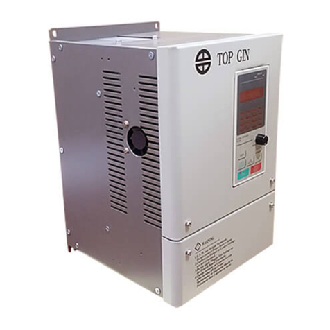
Top Gin TG100 User manual

- 1 -
PREFACE
TOP GIN TG100.
is a small and simple inverter; as easy as using a
contactor. This instruction manual describes
installation, maintenance and inspection,
troubleshooting, and specifications of the TG100.
Read this instruction manual thoroughly before
operation.

- 2 -
NOTES FOR SAFE OPERATION
Read this instruction manual thoroughly before installation, operation,
maintenance or inspection of the TG100. In this manual, NOTES FOR SAFE
OPERATION are classified as “WARNING” or “CAUTION.”
Indicates a potentially hazardous situation which, if not avoided, could result in
death or serious injury to personnel.
Indicates a potentially hazardous situation which, if not avoided, may result in
minor or moderate injury to personnel and damage to equipment. It may also be
used to alert against unsafe practices.
Even items described in may result in a vital accident in some
situations. In either case, follow these important notes.
NOTE
: These are steps to be taken to insure proper operation.
WARNING
!
CAUTION
!
CAUTION
!
NOTE

- 3 -
WARNINGS FOR UL/cUL MARKING
•Do not connect or disconnect wiring, or perform signal checks while the power
supply is turned ON.
• The Inverter internal capacitor is still charged even after the power supply is
turnd OFF. To prevent electric shock, disconnect all power before servicing the
Inverter. Then wait at least one minute after the power supply is disconnected
and all indecators are OFF.
• Do not perform a withstand voltage test on any part of the Inverter. This
electronic equipment uses semiconductors and is vulnerable to high voltage.
• Do not remove the Digital Operator or the blank cover unless the power supply
is turned OFF. Never touch the printed control board (PCB) while the power
supply is turned ON.
• This Inverter is not suitable for use on a circuit capable of delivering more than
18,000 RMS symmetrical amperes, 250volts maximum (220V class units) or
18,000 RMS symmetrical amperes, 480volts maximum (440Vclass units).
WARNINGS FOR CE MARKINGS
• Only basic insulation to meet the requirements of protection class 1 and
overvoltage category II is provided with control circuit terminals. Additional
insulation may be necessary in the end product to conform to CE requirements.
• For 440 V class Inverters, make sure to ground the supply neutral to conform to
CE requirements.
• For conformance to EMC directives, refer to the relevant manuals for the
requirements.

- 4 -

- 5 -
WIRING

- 6 -

- 7 -
OPERATION

- 8 -

- 9 -

- 10 -
CONTENTS
NOTES FOR SAFE OPERATION···································· 2
1. RECEIVING ······························································· 12
zChecking the Name Plate···································· 12
2. MOUNTING································································ 13
zChoosing a Location to Mount the Inverter·········· 13
3. WIRING······································································ 14
zWiring the Main Circuit ········································ 14
zWiring the Control Circuit····································· 15
zWiring Inspection ················································· 16
4. OPERATING THE INVERTER··································· 17
zTest Run ···························································· 17
zOperating the Digital Operator ·························· 19
zLED Description ·················································· 21
zSimple Data Setting ············································ 25
5. PROGRAMMING FEATURES ··································· 26
zConstant Set-up and Initialization ······················· 26
zSelecting V/f pattern ·········································· 27
zSwitching LOCAL/REMOTE Modes···················· 30
zSelecting Run/Stop Commands ·························· 31
zSelecting Frequency Reference·························· 32
zSetting Operation Conditions ···························· 33
Reverse run prohibit ············································ 33
Multi-step speed selection ··································· 33
Operating at low speed········································ 34
Adjusting speed setting signal ····························· 35
Adjusting frequency upper and lower limits ········· 37
Using two accel/decel times ································ 37
Automatic restart after momentary power loss ······················38
Soft-start characteristics ························································39
Torque detection ···································································40
Frequency detection······························································42
Jump frequencies ····················································· 43
Continuing operation by automatic fault reset··········· 43
Operating coasting motor without trip ····················· 44
Holding accel/decel temporarily································ 45
Using frequency meter or ammeter ·························· 46

- 11 -
Calibrating frequency meter or ammeter ·················· 46
Reducing motor noise or leakage current················· 47
Operator stop key selection······································ 49
zSelecting Stopping Method······································· 50
Selecting stopping method ······································ 50
Applying DC injection braking ··································· 51
zBuilding Interface Circuits with External Devices······ 52
Using input signals···················································· 52
Using output signals·················································· 55
zSetting Frequency by Current Reference Input ········ 57
zPreventing motor from stalling (Current limit) ········· 59
zDecreasing Motor Speed Fluctuation ······················· 61
Slip compensation····················································· 61
zMotor Protection ······················································· 62
Motor overload detection ·········································· 62
zSelecting Cooling Fan Operation ···························· 63
zUsing MEMOBUS (MODBUS) Communications
(Optional) ································································ 64
MEMOBUS (MODBUS) communications ················· 64
Communication specifications ·································· 64
6. FAULT DIAGNOSIS ················································· 65
z Protective and Diagnostic Function ······················· 65
z Troubleshooting ······················································ 73
7. SPECIFICATIONS ····················································· 76
zStandard Specifications (220V Class) ······················ 76
zStandard Specifications (440V Class) ······················ 79
zStandard Wiring ······················································ 82
zSequence Input Connection with NPN/PNP
Transistor ································································· 84
zDimensions/Heat Loss·············································· 85
zConstants List··························································· 86

- 12 -
1. RECEIVING
After unpacking the TG100, check the following :
▫ Verify that the part numbers match your purchase order or packing slip.
▫ Check the unit for physical damage that may have occurred during
shipping.
If any part of TG100 is missing or damaged, call for service immediately.
zChecking the name Plate
MODEL
TG 100 L10
SOURCE 220V 50/60 HZ
VOLTS 220V 0.75KW 5.5A
SERIALNO.
TOPGIN MADE IN TAIWAN
CAPACITY 2.0 KVA
INVERTER MODE
INPUT SPEC
OUTPUT SPEC
SERIAL NO.

- 13 -
2. MOUNTING
z Choosing a Location to Mount the Inverter
Be sure the inverter is protected from the following conditions :
▫ Extreme cold and heat. Use only within the ambient temperature range :-10 to
+50ºC (14 to 122ºF)
▫ Rain, moisture
▫ Oil sprays, splashes
▫ Salt spray
▫ Direct sunlight. (Avoid using outdoors)
▫ Corrosive gases (e.g. sulfurized gas) or liquids
▫ Dust or metallic particles in the air.
▫ Physical shock, vibration.
▫ Magnetic noise. (Example : welding machines, power devices, etc.)
▫ High humidity.
▫ Radioactive substances.
▫ Combustibles : thinner, solvents, etc.

- 14 -
3. WIRING
zWiring the Main Circuit

- 15 -

- 16 -

- 17 -

- 18 -
Operation Check Points
▫ Motor rotates smoothly.
▫ Motor rotates in the correct direction.
▫ Motor does not have abnormal vibration or noise.
▫ Acceleration or deceleration is smooth.
▫ Current matching the load flows.
▫ Status indicator LEDs and digital operator display are correct.

- 19 -
● Operating the Digital Operator
All functions of the TG100 are set by the digital operator. Below are
descriptions of the display and keypad sections.
Function display LEDs (Color in parenthesis indicates the color of LED.)
FREF
Frequency reference
setting/monitoring
(GREEN)
FOUT
Output frequency
monitor
(GREEN)
IOUT
Output current
monitor
(GREEN)
MNTR
Multi-function
monitor
(GREEN)
F/R
Operator RUN
command FWD/REV
selection
(GREEN)
LO/RE
LOCAL/REMOTE
Selection
(RED)
PRGM
Constant no./data
(RED)

- 20 -
Table of contents
Other Top Gin Inverter manuals
Popular Inverter manuals by other brands

Mitsubishi Electric
Mitsubishi Electric FR-A8AX instruction manual

Solectria Renewables
Solectria Renewables PVI 15KW Installation and operation manual

Samlexpower
Samlexpower PST-600-12 owner's manual

Coleman
Coleman 58050 Assembly & installation

NF
NF WF1973 instruction manual

Rohde & Schwarz
Rohde & Schwarz R&S SMU200A operating manual