manuals.online logo
Brands
  1. Home
  2. •
  3. Brands
  4. •
  5. Topcon
  6. •
  7. Measuring Instrument
  8. •
  9. Topcon 2LS Taurus User manual

Topcon 2LS Taurus User manual

The TAURUS is classified as a class 3R Laser Product according to IEC Standard Publication
60825-1 Ed.2.0: 2007 and United States Government Code of Federal Regulation FDA CDRH
21CFR Part1040.10 and 1040.11 (Complies with FDA performance standards for laser products
except for deviations pursuant to Laser Notice No.50, dated June 24, 2007.)
CWARNING
• Use of controls or adjustments or performance of procedures other than those specified herein may
result in hazardous radiation exposure.
• Follow the safety instructions on the labels attached to the instrument as well as in this manual to
ensure safe use of this laser product.
• Never intentionally point the laser beam at another person. The laser beam is injurious to the eyes
and skin.
• The laser beam is emitted when the power is turned ON. Before turning the power on, make sure
that persons are not located in the path of the laser beam.
• Secure the instrument in a fixed position before it is used. If it is necessary to hold the instrument by
hand, make sure that persons are not located in the area before the laser is emitted.
• Do not look directly into the laser beam. Doing so could cause permanent eye damage.
• Do not stare at the laser beam. Doing so could cause permanent eye damage.
• Never look at the laser beam through a telescope, binoculars or other optical instruments. Doing so
could cause permanent eye damage.
CCAUTION
• Perform checks at start of work and periodic checks and adjustments with the laser beam emitted
under normal conditions.
• When the instrument is not being used, turn off the power.
• When disposing of the instrument, destroy the battery connector so that the laser beam cannot be
emitted.
• Operate the instrument with due caution to avoid injuries that may be caused by the laser beam
unintentionally striking a person in the eye. Avoid setting the instrument at heights at which the path
of the laser may strike pedestrians or drivers at head height.
• Never point the laser beam at mirrors, windows or surfaces that are highly reflective. The reflected
laser beam could cause serious injury.
• Only those who have received training as per the following items shall use this product.
- Read the Operator's manual for usage procedures for this product.
- Hazardous protection procedures (read this chapter)
- Requisite protective gear (read this chapter)
- Accident reporting procedures (stipulate procedures beforehand for transporting the injured and
contacting physicians in case there are laser-induced injuries). "
• Persons working within the range of the laser beam are advised to wear eye protection which
corresponds to the laser wavelength of the instrument being used.
• Areas in which the laser is used should be posted with a standard laser warning sign.
Laser beam emitted
from here
1
8
15
14
9
10
11
12
2
3
5
7
6
4
16
17
13
18
REPLACING THE BATTERIES
Rotating laser
1Turn the battery cover knob to OPEN and remove the battery cover.
2Pull out the slide board and remove the batteries.
3Insert new batteries as shown by the illustration on the battery cover.
4Replace the battery cover to its original position and turn the battery cover knob to LOCK.
G
• Always replace all 4 batteries at the same time. Do not use a combination of old and new batter-
ies.
• Alkaline batteries are recommended for use with the instrument. (Batteries included upon ship-
ment are for confirmation of operation by the user.) Commercially-available manganese, Ni-CD
and Ni-MH batteries may be used but the operating time will differ to that for alkaline batteries.
• Battery performance generally deteriorates temporarily at low temperatures.However, returning
to room temperature restores normal performance.
LS-1
1Open the battery cover at the back side of level sensor.
2Take out the batteries and replace with new ones (6F22 battery x 1).
3Insert cover tabs in grooves, press the cover down and click to close.
・Please read this operator's manual carefully before using this product.
・Verify that all equipment is included.
C"STANDARD EQUIPMENT"
・The specifications and general appearance of the instrument, and the content of this man-
ual are subject to change without notice.
・Some of the diagrams shown in this manual may be simplified for easier understanding.
Definition of Indication
Definition of Symbols
XGeneral
CWARNING Ignoring this indication and making an operation error could possibly result in
death or serious injury to the operator.
CCAUTION Ignoring this indication and making an operation error could possibly result in
minor injury or property damage.
JThis symbol indicates items for which caution (hazard warnings inclusive) is
urged. Specific details are printed in or near the symbol.
DThis symbol indicates items which are prohibited. Specific details are printed in
or near the symbol.
IThis symbol indicates items which must always be performed. Specific details
are printed in or near the symbol.
CWARNING
DDo not use the unit in areas exposed to high amounts of dust or ash, in areas where
there is inadequate ventilation, or near combustible materials. An explosion could oc-
cur.
GDo not perform disassembly or rebuilding. Fire, electric shock, burns or hazardous ra-
diation exposure could result.
EWhen securing the instrument in the carrying case make sure that all catches,
including the side catches, are closed. Failure to do so could result in the instrument
falling out while being carried, causing injury.
CCAUTION
DDo not use the carrying case as a footstool. The case is slippery and unstable so a
person could slip and fall off it.
DDo not place the instrument in a case with a damaged catch or handle. The case or
instrument could be dropped and cause injury.
XTripod
XPower Supply
PRECAUTIONS
Before starting work or during operation, check that the instrument is functioning correctly and per-
formance is normal.
TAURUS should be used with the level sensor (LS-1), a standard equipment. We do not guarantee
precision noted in this instruction manual when used with other level sensors.
STORAGE PRECAUTIONS
Always clean the instrument after use.
Use a clean cloth moistened with neutral detergent or water.
Never use an abrasive cleaner, ether, thinner, benzene, or other solvents.
Always make sure the instrument is completely dry before storing. Dry any moisture with a soft,
clean cloth.
PRECAUTIONS REGARDING LONG-TERM STORAGE
Remove batteries before storing when the instrument will not be used for periods on 1 month or
more.Batteries may leak fluid when left inside the insturment causing malfunction.
CCAUTION
EWhen mounting the instrument to the tripod, tighten the centering screw securely. Fail-
ure to tighten the screw properly could result in the instrument falling off the tripod,
causing injury.
ETighten securely the leg fixing screws of the tripod on which the instrument is mounted.
Failure to tighten the screws could result in the tripod collapsing, causing injury.
DDo not carry the tripod with the tripod shoes pointed at other persons. A person could
be injured if struck by the tripod shoes.
EKeep hands and feet away from the tripod shoes when fixing the tripod in the ground.
A hand or foot stab wound could result.
ETighten the leg fixing screws securely before carrying the tripod. Failure to tighten the
screws could lead to the tripod legs extending, causing injury.
CWARNING
DDo not use voltage other than the specified power supply voltage. Fire or electrical
shock could result.
DDo not use batteries if the contacts are wet. Resultant shorting could lead to fire or
burns.
DDo not heat or throw batteries into fire. An explosion could occur, resulting in injury.
CCAUTION
DDo not touch liquid leaking from batteries. Harmful chemicals could cause burns or
blisters.
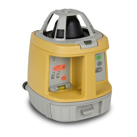
PARTS AND FUNCTIONS OF THE INSTRUMENT 1. Rotary head
Laser beam emits from here.
2. Protective glass
3. Handle
4. Manual mode ON switch
ON: Push twice continuously.
OFF: Push once.
Manual mode
- Auto-leveling function is not active.
- Height alert function is not active.
5. Manual mode ON (Red LED)
Auto leveling does not function.
6. Height alert OFF switch
OFF:Push twice continuously.
ON:Push once.
7. Height alert OFF (Red LED)
Height alert does not function.
8. Battery power (Red LED)
Blinking:
The power is low, but laser is still usable. (Blinking continues for
one minute.)
On Solid:
Dead batteries. Replace the batteries with new ones. (The lamp is
solid for five minutes, then turned off automatically.)
9. Auto leveling (Green LED)
Blinking quickly:
Auto leveling is in process.
Blinking slowly:
Auto leveling is almost complete.
On Solid:
Auto leveling is complete.
10. Power switch
Turn the instrument ON or OFF.
11. Battery door knob
12. Battery door
Class 3R Laser Product
For the safe use of the product and prevention of injury to operators and other persons as well as
prevention of property damage, items which should be observed are indicated by an exclamation
point within a triangle used with WARNING and CAUTION statements in this operator's manual.
The definitions of the indications are listed below. Be sure you understand them before reading the
manual's main text.
Make sure all of the following are included.
13. Indicator
When moving the level sensor and detecting the datum position,
"====" (normal precision) or "-------" (high precision) is indicated.
Directional arrows and audio signals assist in locating the on-
grade position as the laser strikes the beam receiving window.
(Top of level sensor is 36mm (1 5/12") from on-grade index for
offset marking.)
The indicators are located on front and back sides of the instru-
ment.
14. Beam receiving window
Turn the beam receiving window side towards TAURUS to detect
the laser beam.
15. Power switch
Turns the detector ON/OFF.
Auto-cut off function
The power will be turned off automatically if no laser beam is
detected for approximately 20 minutes. (To turn on the level sen-
sor, press the power switch again.)
16. Precision Setting Shifting Switch
Two leveling precision options are available, normal precision
(±2mm) and high precision (±1mm). By pressing this switch, the
precision options are switched alternately. Confirm the selected
precision option by viewing the indicator. (Normal precision is
set when turning on the power switch.)
17. Audio tone switch
By pressing this switch, ON/OFF of buzzer sound is switched
alternately.
18. Buzzer speaker
Slide board
LASER SAFETY INFORMATION
PRECAUTIONS FOR SAFE OPERATION
STANDARD EQUIPMENT
Rotating laser LS-1
INSTRUCTION MANUAL
ROTATING LASER
After using the instrument, store it as shown below.
HOW TO STORE
• The user of this product is expected to follow all operating instructions and make periodic checks
of the product's performance.
• The manufacturer, or its representatives, assumes no responsibility for results of faulty or intentional
usage or misuse including any direct, indirect, consequential damage, or loss of profits.
• The manufacturer, or its representatives, assumes no responsibility for consequential damage, or
loss of profits due to any natural disaster, (earthquake, storms, floods etc.), fire, accident, or an act
of a third party and/or usage under unusual conditions.
• The manufacturer, or its representatives, assumes no responsibility for any damage (change of
data, loss of data, loss of profits, an interruption of business etc.) caused by use of the product or
an unusable product.
• The manufacturer, or its representatives, assumes no responsibility for any damage, and loss of
profits caused by usage different to that explained in the operator's manual.
• The manufacturer, or its representatives, assumes no responsibility for damage caused by incorrect
operation, or action resulting from connecting to other products.
EXCEPTIONS FROM RESPONSIBILITY
1 TAURUS Instrument . . . . . . . . . . . . . . . 1
2 Level Sensor (LS-1) . . . . . . . . . . . . . . . 1
3 Carrying case . . . . . . . . . . . . . . . . . . . . 1
4 Level Sensor Holder (Holder-7) . . . . . . 1
5 C-size dry cell batterys . . . . . . . . . . . . . 4
6 9V dry cell battery . . . . . . . . . . . . . . . . . 1
7 Operator's manual . . . . . . . . . . . . . . . . . 1
SPECIFICATIONS
Rotating Laser
Accuracy : 2.0mm/20m (±20”)
Automatic correction range : ±3°
Operating range : Diameter Approx. 4m to 300m (When using LS-1)
Rotational speeds : 600r.p.m
Laser source : Laser diode (Visible, 635nm)
Laser output : 2.4mW
Safety standard for laser beam : CDRH (FDA) Class IIIa, IEC Class 3R
Power supply : 4 x C size dry cell batteries (alkaline)
Operating time : Approx. 60 hours at +20°C (+68°F)
Protection against water and dust : IP56 (Based on the standard IEC60529)
Operating temperature : -20°C to +50°C (-4°F to +122°F)
Dimensions : 167(L)x192.5(W)x189(H)mm (6.6 x 7.6 x 7.5 in)
Weight : 2.0kg [4.4 lbs] (Including dry cell batteries)
Level Sensor
Beam detection window : 45mm (1.78 in)
Beam detection precision : High precision: ±1mm (±0.04 in)/Normal precision: ±2mm (±0.08 in)
Beam detection indication : Liquid crystal (both sides) and buzzer
Power source : 1 x 9v dry cell battery
Operating time : Approx. 35 hours
Auto shut-off delay : Approx. 20 minutes without beam detection
Protection against water and dust : IP65 (Based on the standard IEC60529)
Operating temperature : -20°C to +50°C (-4°F to +122°F)
Dimensions : 135(L)x65(W)x24.5(H)mm (5.3 x 2.6 x 1.0 in)
Weight : 196g [6.9 oz] (including dry cell batteries)
[Checking]
1Set up a tripod approx. 50m (160ft) from a wall. Mount the instrument on the tripod, facing the X1
side toward the wall.
2Turn the instrument on and allow auto-leveling to complete.
3Put the level sensor in fine detection mode by pressing the On-Grade precision switch.
4By using the level sensor, mark the center position of laser beam on the wall. (X1)
5Turn off the instrument.
Loosen the tripod screw, rotate the instrument 180 degrees and re-secure it on the tripod. The X2
side of the instrument faces toward the wall.
When rotating the instrument, avoid changing the height.
6Turn the unit on again and allow auto-leveling to complete.
7By using the level sensor, mark the center position of laser beam on the wall. (X2)
8If the difference value of marked two laser beam heights (difference value of X1 and X2) are less
than 7mm, adjustments are not needed. The difference value is greater than 7mm, adjust the instru-
ment as described in right. *
9Check the Y1 (handle) side as the same way.
*If the difference value is greater than 60mm (2 3/8 inches), contact your Topcon dealer.
CHECKS AND ADJUSTMENT [To calibrate the X axis]
1Face the X1 side of the instrument (panel side) toward a wall, press the Power switch while
pressing the height alert OFF switch.
Then the height alert OFF lamp will light, and manual mode ON lamp will blink.
2Press the height alert OFF switch to calibrate the X axis. The manual mode ON lamp will light.
When auto-leveling finishes, the laser beam will emit.
3Using the level sensor, mark the on-grade height of laser beam on a wall.
4Rotate the instrument 180 degrees to face X2 side toward a wall.
5In the same way as step 3, mark the on-grade height of laser beam on a wall.
6By pressing the manual mode ON switch (laser beam moves up), or Power switch (laser beam
moves down), adjust the on-grade height of the beam until it is precisely centered between the
marks made in steps 3 and 5.
7Press the height alert OFF switch to memorize the new laser beam calibration. The height alert OFF
lamp will blink. Power will shut off automatically when the calibration memorization is complete.
[To calibrate the Y axis]
1Face the Y1 side of the instrument (handle side) toward a wall, press the Power switch while
pressing the height alert OFF switch.
Then the height alert OFF lamp will light, and manual mode ON lamp will blink.
2Press the Power switch again. The auto leveling lamp will light.
3Press the height alert OFF switch to calibrate the Y axis. The auto leveling lamp will light.
4Using the level sensor, mark the on-grade height of laser beam on a wall.
5Rotate the instrument 180 degrees to face Y2 side toward a wall.
6In the same way as step 4, mark the on-grade height of laser beam on a wall.
7By pressing the manual mode ON switch (laser beam moves up), or Power switch (laser beam
moves down), adjust the on-grade height of the beam until it is precisely centered between the
marks made in steps 4 and 6.
8Press the height alert OFF switch to memorize the new laser beam calibration. The height alert OFF
lamp will blink. Power will shut off automatically when the calibration memorization is complete.
To discontinue calibration the instrument, press the Power switch while pressing the height alert
OFF switch.
When calibration is memorizing, if the height alert lamp continues to blink quickly and power does
not shut-off automatically, please contact your local Topcon dealer.
1Set the instrument to the tripod or smooth surface.
2Make sure instrument is roughly level.
3Press power switch (ON).
4Press power switch on level sensor (ON).
5Select the precision mode by pressing the On-Grade precision
switch.
6Locate the on-grade position "-------" or "====" by moving the level
sensor up and down.
7Mark the position of On-Grade index.
(Top of the level sensor is 36mm [1 5/12"] from index for offset
marking.)
G
• TAURUS should be used with the level sensor (LS-1), a standard
equipment. We do not guarantee precision noted in this instruction
manual when used with other level sensors.
High precision mode
Normal precision mode
Battery remaining display
Lower than datum position
(Audio signal: High-pitch,
frequent beep sound)
Datum position
(Audio signal: Continuous
beep sound)
Higher than datum position
(Audio signal: Low frequent
beep sound)
OPERATION
Use the table below to determine operation errors indicated by blinking lamps on
the control panel. If corrective action listed does not correct error, please contact
your local Topcon dealer.
Lamp indication Error Cause Corrective Action
Lamp B, C and D blink in turn Self-leveling range
error
The instrument tilt was too
large when set up.
Correct tilt of the instrument until it is less than 3°.
Lamp A lights Battery power error Remaining battery power
is insufficient
Replace all 4 batteries at the same time.
Lamp B, C and D blink simultaneously Tilt error Setup position of the in-
strument has changed
dramatically.
Turn power off, rough level the instrument, then turn power
on again. Check height of the laser beam as it may have
changed.
Lamp D blinks quickly Calibration error Adjustable range exceed-
ed.
Repeat calibration procedure. If error repeats contact your
local dealer.
Lamp A, B, C and D blink simultaneously Internal error Internal fault Turn power off, then on again.If error repeats contact your
local dealer.
36mm
ERROR DISPLAYS
1. Checking and adjusting calibration
Horizontal calibration of the laser beam can be checked by the user.
LS-1
http://www.topcon.co.jp
GLOBAL GATEWAY http://global.topcon.com/
Please see the following website for contact addresses.
How To Operate
Example Operational Height Alert Function
When the instrument system detects a shock, this function informs the
operator of it.
• When the instrument's installation status (height) is sharply changed
by the contact of the operator or the like, this function stops auto lev-
eling to keep the operation accuracy and informs the operator of the
situation. The three lamps blink at the same time as shown at the
right.
• After 1 minute has passed since the auto leveling function was acti-
vated and the laser beam was emitted, this function works.
• The height alert function does not work in the "Manual" mode.
Shock is given to
the instrument. Height alert status
[How to reset]
1Turn off the power switch.
2Check whether the instrument is installed correctly.
3Turn on the power switch. Auto leveling starts again. After auto lev-
eling is finished, the laser beam is emitted.
4Make sure that the laser beam is set at the correct height. Then,
restart the operation.
The three lamps blink at the same time and
the rotary head rotates at low speed.
Buzzer sound ON/OFF display
X1 (panel side) X2
Y1 (handle side)
Y2
D C B
A
X1
Level Sensor
Wall
Approx. 50m
X1 Laser beam
Laser point of X1
Approx. 50m
X1
X2
X2 Laser beam
2. Checking cone error
Perform the following check after completing horizontal calibration procedure.
[Checking]
1Set up the laser centered between two walls approximately 40m (131ft) apart. Orient the instrument so one axis, either X or Y, is facing the walls.
2Locate and mark the position of the rotating laser beam on both walls using the level sensor.
3Turn off the instrument and move the instrument closer to wall A (1m to 2m /3 ft to 6 ft).
4Do not change the axis orientation of the instrument. Turn the instrument on.
5Again locate and mark the position of the rotating laser beam on both walls using the level sensor.
6Measure the distance between the first and second marks on each wall.
7If the difference between each set of marks is less than 4mm (5/32 of an inch), no error exists.
* If the difference value is greater than 4mm (5/32 inch), contact your Topcon dealer.
Cone error
Datum position
Wall A Wall B Wall A Wall B
X1
31369 90040

Other Topcon Measuring Instrument manuals

Topcon GTS-230 Series User manual

Topcon

Topcon GTS-230 Series User manual

Topcon BM-7AC User manual

Topcon

Topcon BM-7AC User manual

Topcon RL-H4C User manual

Topcon

Topcon RL-H4C User manual

Topcon GM-100 Series User manual

Topcon

Topcon GM-100 Series User manual

Topcon RL-VH3G User manual

Topcon

Topcon RL-VH3G User manual

Topcon UVR-T2 User manual

Topcon

Topcon UVR-T2 User manual

Topcon SR-LEDW User manual

Topcon

Topcon SR-LEDW User manual

Topcon GTS-600 Series User manual

Topcon

Topcon GTS-600 Series User manual

Topcon UA-10 Series User manual

Topcon

Topcon UA-10 Series User manual

Topcon RT-5SW User manual

Topcon

Topcon RT-5SW User manual

Topcon IM-600 User manual

Topcon

Topcon IM-600 User manual

Topcon RC-5A Reference manual

Topcon

Topcon RC-5A Reference manual

Topcon IS Series User manual

Topcon

Topcon IS Series User manual

Topcon RL-H5A User manual

Topcon

Topcon RL-H5A User manual

Topcon OS Series User manual

Topcon

Topcon OS Series User manual

Topcon GTS-230W Series User manual

Topcon

Topcon GTS-230W Series User manual

Topcon BM-9A User manual

Topcon

Topcon BM-9A User manual

Topcon CL-300 User manual

Topcon

Topcon CL-300 User manual

Topcon CL-200 User manual

Topcon

Topcon CL-200 User manual

Topcon i-33 User manual

Topcon

Topcon i-33 User manual

Topcon 3D-MC2 User manual

Topcon

Topcon 3D-MC2 User manual

Topcon Synergy GM-50 series User manual

Topcon

Topcon Synergy GM-50 series User manual

Topcon RL-VH3C User manual

Topcon

Topcon RL-VH3C User manual

Topcon GTS-821A, GTS-822A, GTS-823A, GTS-825A User manual

Topcon

Topcon GTS-821A, GTS-822A, GTS-823A, GTS-825A User manual

Popular Measuring Instrument manuals by other brands

Leica Lino ML90 user manual

Leica

Leica Lino ML90 user manual

WAGER 7500 manual

WAGER

WAGER 7500 manual

Bosch Rexroth BODAS DSA/12 instruction manual

Bosch

Bosch Rexroth BODAS DSA/12 instruction manual

Kurtz Ersa DTM 100 operating instructions

Kurtz Ersa

Kurtz Ersa DTM 100 operating instructions

Conrad RF Explorer operating instructions

Conrad

Conrad RF Explorer operating instructions

Endress+Hauser Cerabar S PMC71 manual

Endress+Hauser

Endress+Hauser Cerabar S PMC71 manual

Kobold **C30R Series operating instructions

Kobold

Kobold **C30R Series operating instructions

Newport Electronics 215-2 Operator's manual

Newport Electronics

Newport Electronics 215-2 Operator's manual

Endress+Hauser SpectraSensors J22 TDLAS operating instructions

Endress+Hauser

Endress+Hauser SpectraSensors J22 TDLAS operating instructions

Leupold RX-FullDraw 3 user manual

Leupold

Leupold RX-FullDraw 3 user manual

MANN+HUMMEL SPB 358 manual

MANN+HUMMEL

MANN+HUMMEL SPB 358 manual

Fluidwell D Series manual

Fluidwell

Fluidwell D Series manual

Ametek Reichert REFRACTIX 13910000 Instructions for use

Ametek

Ametek Reichert REFRACTIX 13910000 Instructions for use

Brookfield DV-II+ operating instructions

Brookfield

Brookfield DV-II+ operating instructions

Pulsar Imp+i.s. instruction manual

Pulsar

Pulsar Imp+i.s. instruction manual

Brandson Equipment 304329/20200206NB102 user manual

Brandson Equipment

Brandson Equipment 304329/20200206NB102 user manual

Fox Thermal Instruments FT1 user manual

Fox Thermal Instruments

Fox Thermal Instruments FT1 user manual

Endress+Hauser Proline Promass 83 Brief operating instructions

Endress+Hauser

Endress+Hauser Proline Promass 83 Brief operating instructions

manuals.online logo
manuals.online logoBrands
  • About & Mission
  • Contact us
  • Privacy Policy
  • Terms and Conditions

Copyright 2025 Manuals.Online. All Rights Reserved.