Topdon PulseQ AC Lite User manual

1
AC Lite
AC EV Charger User Manual

CONTENTS
Section 1 - Precautions ............................................................................. 4
Section 2 - Standards Compliance ............................................................................ 7
Section 3 - Product Overview & Info ............................................................................ 9
Section 4 - What's in the Box? ........................................................................... 13
Section 5 - Installation ............................................................................ 14
Section 6 - LED Indicators ........................................................................... 30
Section 7 - Fault Handling ............................................................................. 31
Section 8 - Warranty ............................................................................ 32

4
Section 1 - Precautions
1.1 IMPORTANT SAFETY PRECAUTIONS
WARNING - When using electric products, the tool's safety precautions
should always be followed. Follow the instructions below closely.
Read all the instructions before using this product. This manual contains
important instructions for the PulseQ AC Lite charger which shall be
followed during the installation, operation, and maintenance of the charger.
Children should be supervised if they are in the vicinity of the PulseQ AC
Lite while the PulseQ AC Lite is in use. Children should not use this device.
Do not put any of your or another person's body, clothing, or accessories
into the tool's electric vehicle connector.
Do not use this product if the charging cable is frayed, has broken
insulation, or has any other signs of damage.
Do not use this product if the enclosure or the charging plug is broken,
cracked, open, or shows any other indication of damage.
Note the the operating temperature rating (-30°C to +50°C).
Certied AC Surge Protection Device (SPD) should be installed upstream close
to the charging station. SPDs shall comply with standard IEC/EN 61643-11, with
specication Up ≤ 2.5kV.
Certied Circuit Breakers should be installed upstream close to the charging
station, or build in RCD. Circuit breaker, if any, shall comply with standard with
IEC 60898-1 or IEC 60947-2 or IEC 61009-1.
1.
2.
3.
4.
5.
6.
Breaker Current RatingModel
PulseQ AC Lite_7K_C5_EU
PulseQ AC Lite_11K_C7_EU
PulseQ AC Lite_22K_C5_EU
40A 1-Phase
20A 3-Phase
40A 3-Phase
5
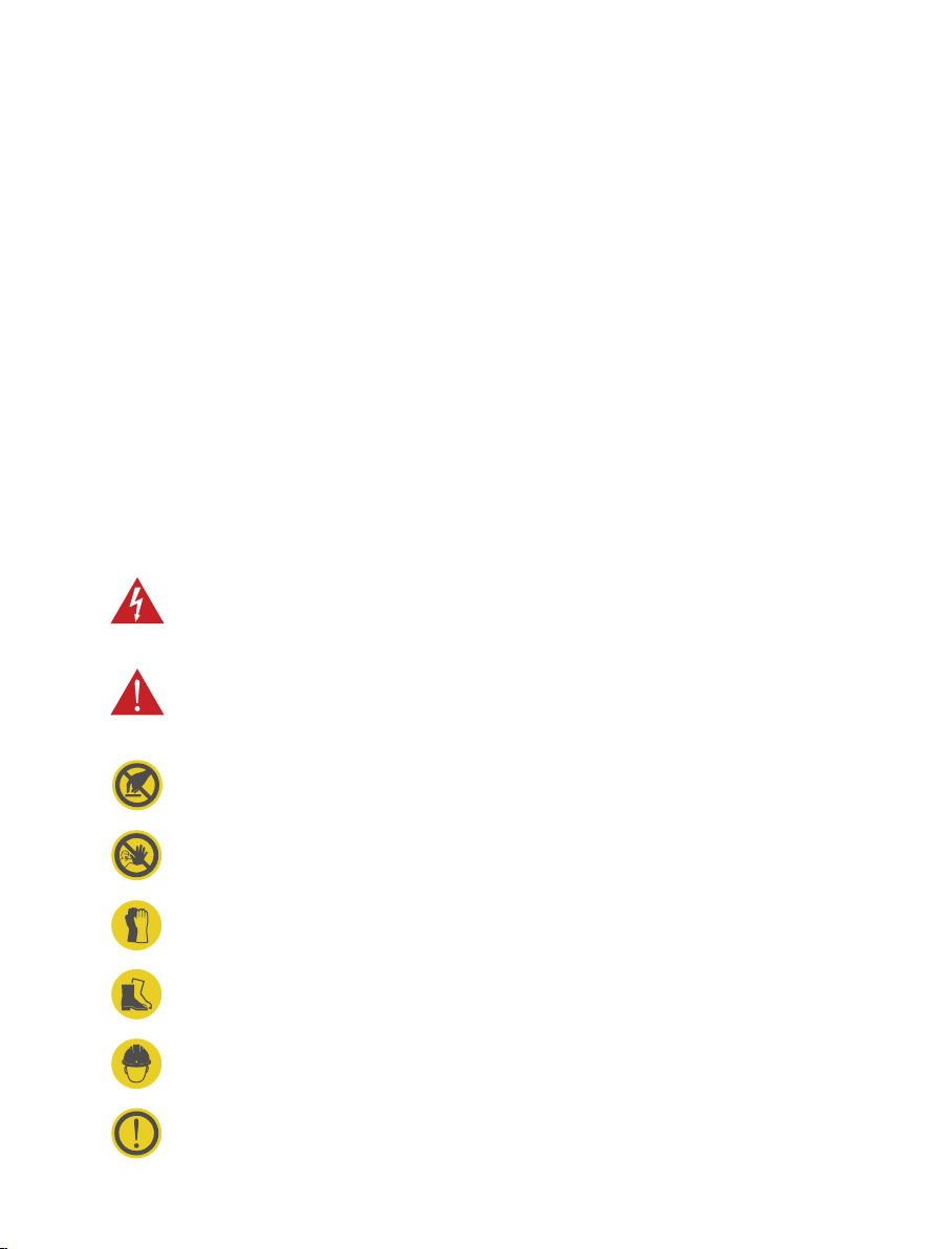
CAUTION: Warns of electrical hazards.
This sign is intended to alert the user that severe personal injury or substantial
property damage can result if the device is not operated as requested.
ATTENTION: Warns of a dangerous spot or dangerous situation.
This sign is intended to alert the user that minor personal injury or material
damage can result if the device is not operated as requested.
CAUTION: Do not touch in case of Electrostatic Discharge (ESD).
Indicates possible consequences of touching electrostatically sensitive
components.
No access for unauthorized persons.
Wear safety gloves
Use protective footwear.
Must wear a safety helmet.
Indicates important texts, notes, or tips.
All these protection devices shall be chosen with appropriated technical
specication, ie working voltage ≥ charging station working voltage, working
current ≥ charging station working current, Ingress Protection (IP) ≥ IP54 or
installed inside IP54 protection box for outdoor use.
1.2 SAFETY NOTES
1.2.1 Safety Signs Used
The following types of signs are used in this manual and on the charger. They must be
adhered to.

6
1.2.3 Safety Precautions for Operation
1.2.4 Safety Precautions for Maintenance
It is strictly forbidden for minors or persons of restricted capacity to be near the
charger while in operation. This is to avoid injury.
Forced charging is strictly forbidden when the electric vehicle or charger fails.
The electric vehicles can only be charged when the engine is off and the vehicle
is stationary. Do not charge in rainy and thunderous weather.
Do not use the charger if the charging plug or charging cable is defective,
cracked, worn, broken or the charging cable is exposed.
It is recommended that charger is routinely inspected at least once a week.
Do not put ammable, explosive, or combustible materials, chemicals,
combustible vapors, or other dangerous goods near the charger, due to risk of
re.
Keep the charging plug clean and dry. Wipe with a clean, dry cloth if soiled.
Personnel must always wear protective gloves and footwear when
performing maintenance work.
1.2.2 Safety Precautions for Installation
Installation must be performed carefully due to the risk of electric shock.
The charger must be installed vertically to allow for ventilation. Do not install on
surfaces that vibrate or where the device could be at risk of impact.
Install in noncombustible areas due to risk of re.
Do not drop any foreign objects, especially metal objects, inside the charger
due to a risk of re.
Safety gear (helmet, gloves & protective footwear) must be
worn when installing the EV charger.

7
Cable
Conforms to IEC 61851-1: 2017, IEC 62196-2
According to IEC 61851-1, the Charging mode of PulseQ AC Lite is Mode 3, and charging
connection is Case C.
Fig. 2-1
Mode 3:
A method for the connection of an EV to an AC EV supply equipment
permanently connected to an AC supply network, with a control pilot function
that extends from the AC EV supply equipment to the EV.
Case C:
Connection of an EV to a supply network utilizing a cable and vehicle connector
permanently attached to the EV charger.
Section 2 - Standards Compliance
2.1 Safety Standard(s)
2.2 Charging Mode and Connection
EV charger
Vehicle inlet
Vehicle
connector

8
The charging plug of the PulseQ AC Lite meets IEC 62196-2, Type 2.
The PulseQ AC Lite provides a Type 2 female plug with charging cable, which only charges
EVs with a Type 2 charging socket (vehicle inlet).
2.3 Charging Interface
CP
NPE L1
L3 L2
PP
Fig. 2-2 Schematic Diagram of Type 2 Interface
9
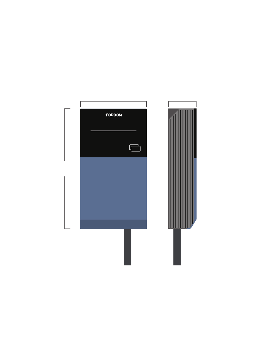
The shape & dimensions of the PulseQ AC Lite charger are shown in Fig. 3-1
Fig. 3-1 Shape & Dimensions of PulseQ AC Lite
Section 3 - Product Overview &
Info
3.1 Shape & Dimensions
340mm
189mm 90mm
CARD

10
The block diagram of the PulseQ AC Lite charger is shown as Fig. 3-2
It is widely used in various European households for electric vehicle charging, as well as
various chargers, parking lots, community garages and public electric vehicle charging
areas.
IEC 62196-2, Type 2 plug with 5m cable /
IEC 62196-2, Type 2 plug with 7.5m cable
Note: Extension cords are not used.
230±10% Vac, 50Hz
32A 1-Phase
7kW
16A 3-Phase
11kW
400±10% Vac, 50Hz
32A 3-Phase
22kW
Rated Voltage
Rated Current
Rated Power
Charging Interface
Fig. 3-2 Block Diagram
LED
RCMU
type A+
6mADC
RFID reader Wi-Fi & BT
LAN
PT&CT
RS-485
Charging
interface
Main CPU
3.2 Block Diagram
3.3 Specications
3.3.1 Electrical Specications
Model Number PulseQ AC Lite

11
3.3.2 Functional Descriptions
Mode 3
Local: Plug and play
RFID reader mode
Charging status indicator
Ethernet (RJ45 interface)
Supports OCPP 1.6J Protocol (Optional)
RS-485 with special communication protocols
Surge protection, over temperature, over / under
voltage, over current, LN reverse polarity, leakage,
ground protection
RAMU, Type A IΔn=30mA + IΔdc=6mA
(Conforms to IEC 62955, IEC 61008)
Charging Mode
Charging Control
Indicator Lights
Communication Interface
Communication Interface (Optional)
Safety Protection
RCD Built-in
Note: To toggle between the Plug and Play and RFID reader charging modes,
touch the supplied charging card on the charger for more than 5 seconds
(until a beep sound is heard). After the RFID reader mode is enabled, touch
the card on the charger to start / stop charging (charging plug should be
connected before you can start charging).
Radio parameters
Item
WIFI
Bluetooth
Item
RFID
Operating Frequency Range
2400-2483.5MHz
2400-2483.5MHz
Operating Frequency Range
13.56MHz
Maximum Transmitting power
<18dBm
<2dBm
Transmitting Field Strength
< 5 dBµA/m @ 3m
Antenna Gain
+3dBi
+2dBi
Antenna Gain
+0dBi

12
3.3.4 Ambient Conditions
≤ 2000m
-40 ~ +80°C
-30 ~ +50°C
≤ 95%RH, no water droplet condensation
< 0.5G, no acute vibration and impact
Can be installed indoors or outdoors. Should be
installed in an area with good ventilation, and not
near ammable or explosive gases.
Altitude
Storage Temperature
Operating Temperature
Relative Humidity
Vibration
Installation Location
3.3.3 Mechanical Parameters
Wall-mounted
≤5.9kg (5m cable), ≤7.1kg (7.5m cable)
340mm × 189mm × 90mm
IP65
IK10
Mounting
Net Weight
Dimensions (H×W×D)
IP Code
IK Code
13
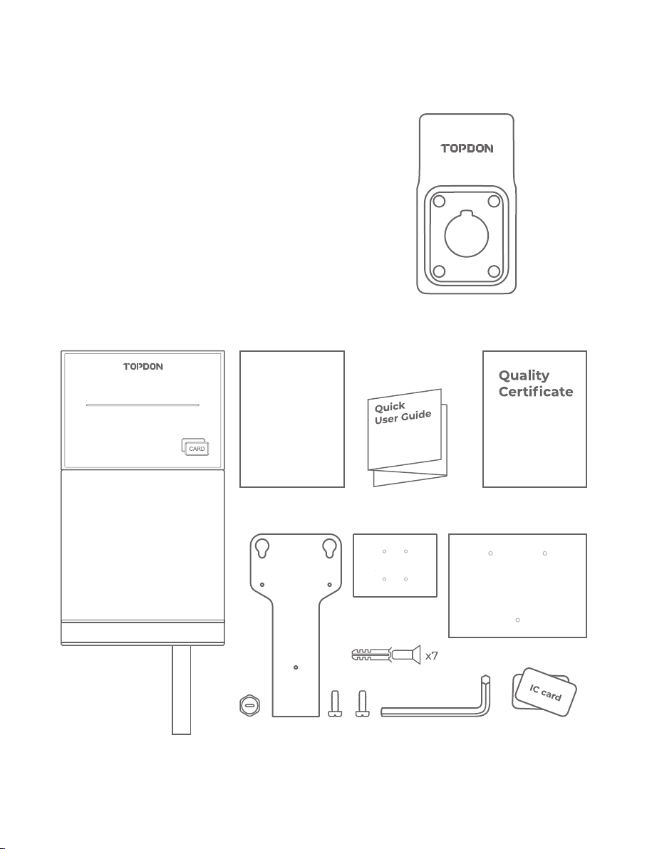
AC EV Charger
Charging Dock
Wall-mounting Accessories
User Manual
Quick User Guide
Quality Certicate
Wall Installation Template
Charging Dock Installation Template
M5×40mm Expansion Bolt
Charging Card
Hex Screwdriver
a
b
d
c k j
e
h
i
f
g
a.
b.
c.
d.
e.
f.
g.
h.
i.
j.
k.
1
1
1
1
1
1
1
1
7
2
1
Section 4 - What's in the Box?
User
Manual

14
When unpacking, please carefully check the following:
Whether the accessories are missing according to the packing list.
Whether there is any damage to the product that occured during transportation.
Whether the model and specication of the machine's nameplate are consistent with
the order requirements.
In order to ensure the long-term stable operation of the product, it is recommended to
avoid installing chargers in extreme weather, especially as low or high ambient
temperatures may affect the installation effect due to expansions and contractions from
temperature changes.
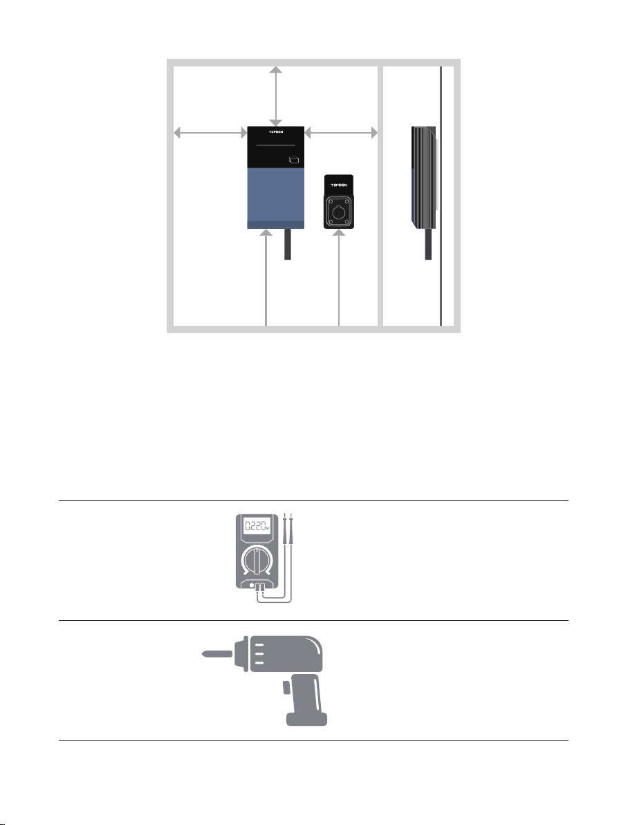
Space requirement: When the charger is xed on the wall, the minimum space
requirements are shown in Fig. 5-1.
It is suggested that the charger should be installed in a place with good ventilation, no
direct sunlight and sheltered from wind and rain. In order to ensure good ventilation,
mount the charger vertically with at least the minimum space around all sides.
When transporting or moving the EV charger, pay attention to the following points to
ensure product safety:
Section 5 - Installation
5.1 Pre-Installation Inspection
5.2 Pre-work Preparation
If any damage or missing parts are found, please do not start the installation,
and contact your vendor as soon as possible.
This product is electrical equipment. It should be handled with care, avoiding
violent vibration and impact.
The charger shall not be transported by dragging the charging connector or
the charging cable.
Please keep the packing box and packing materials for 1 month for future
handling.
The paper packaging is recyclable.
15
Please have the following tools prepared before installing
No. Tool Name Schematic Picture Main Uses
Checking the electrical connection
and measuring the voltage
Drilling mounting holes in the wall
Multimeter
Electric impact
drill
1
2
Fig. 5-1 Minimum Space Requirements for Wall Mounting
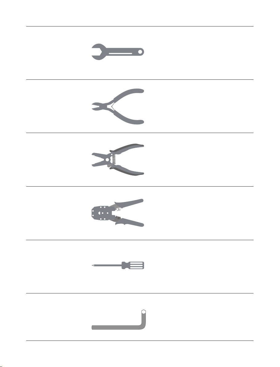
5.3 Tools for Installation
200mm
(min)
200mm
(min)
200mm
(min)
≈1200-
1300mm
≈500-
1400mm
CARD
16
Fastening bolts
Peeling cables
Fastening screws
Cutting cables
Pressing cable terminal
Fastening screws
Wrench
Wire stripper
Phillips
screwdriver
Diagonal pliers
Crimping pliers
Hex screwdriver
(included)
3
5
7
4
6
8

17
Fastening screws to a specied
torque
Measuring distance
Ensuring a level installation
Marking mounting holes
Driving expansion anchors into
the mounting holes
Torque
screwdriver
Tape measure
Level tool
Pencil
Hammer
9
11
10
12
13
18
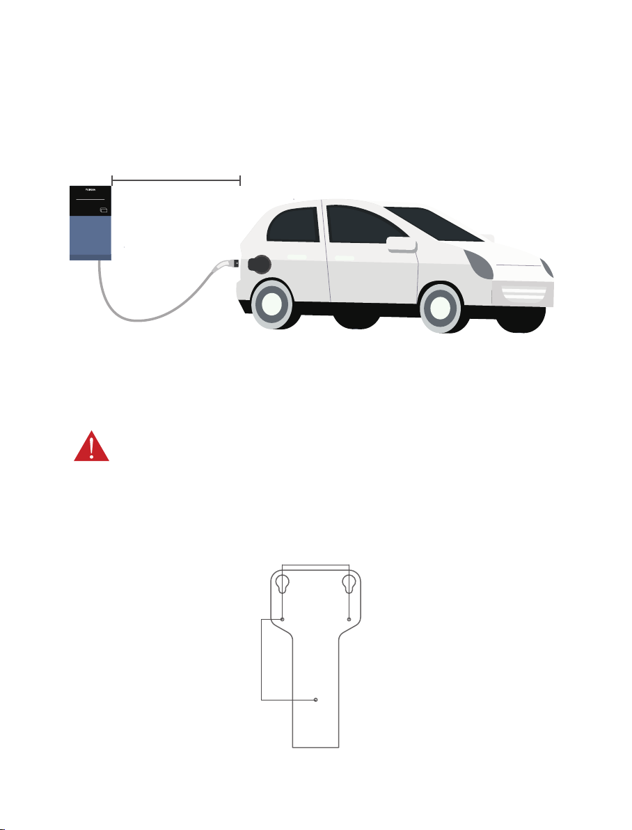
Before installation, ensure the homeowner has chosen an installation location that allows
the charging cable to reach the car's charging port while still providing slack (See Fig. 5-2).
1. Refer to the Fig. 5-3 to understand the dimensions of the wall bracket. Please make sure
the space on the wall is at least 3.43" × 4.21" (87mm × 107mm).
Fig. 5-3
Fig. 5-2
5.4 Wall Bracket Installation
WARNING: In areas with frequent thunderstorms, add surge protection at the
service panel for all circuits. Ensure all power and ground connections,
especially those at the breaker and bus bar, are clean and tight. Remove all
oxide from all conductors and terminals before connecting any wiring.
87mm
107mm
CARD
19
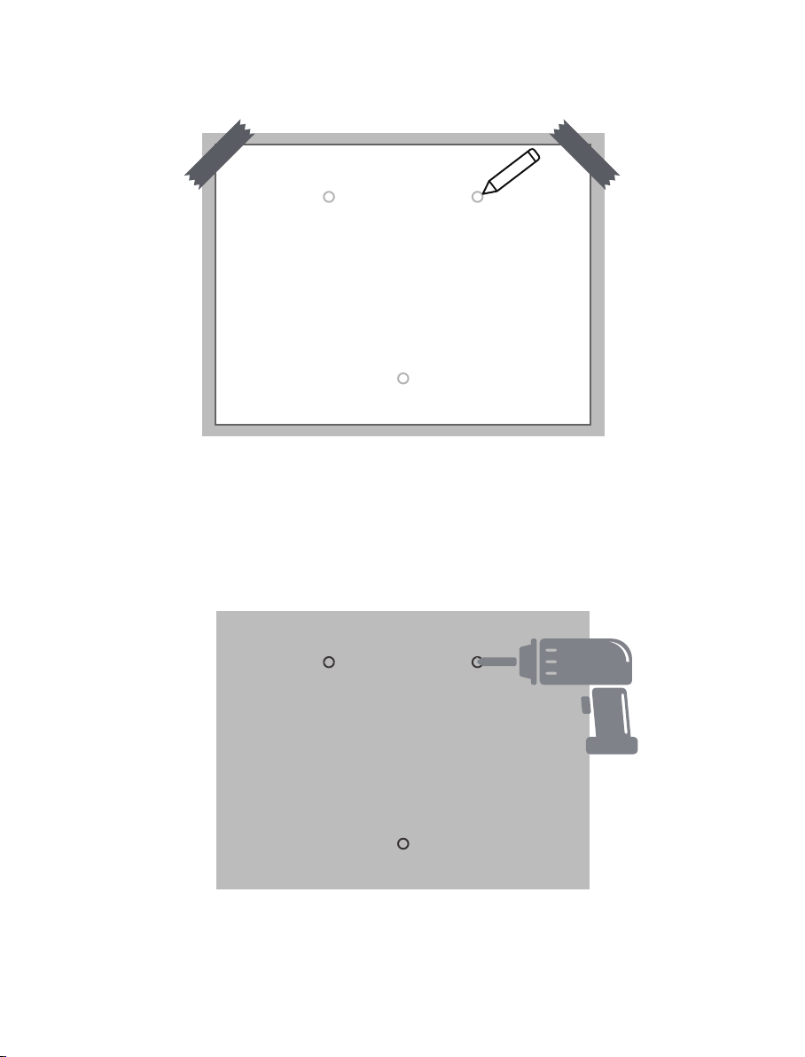
2. Mark the mounting holes on the wall with the installation template. (See Fig. 5-4)
3. Drill the mounting holes into the wall with a depth of at least 1.57" (40 mm). (See Fig. 5-5)
Fig. 5-4
Fig. 5-5
20
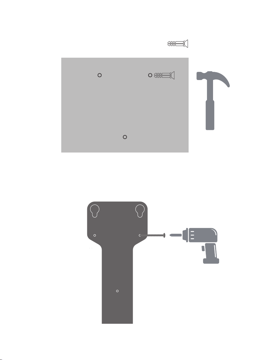
4. Hammer the plastic expansion anchors into the holes. (See Fig. 5-6)
5. Fix the bracket to the wall with the expansion screws (See Fig. 5-7) included in the
package.
Fig. 5-6
Fig. 5-7
1.57"
21
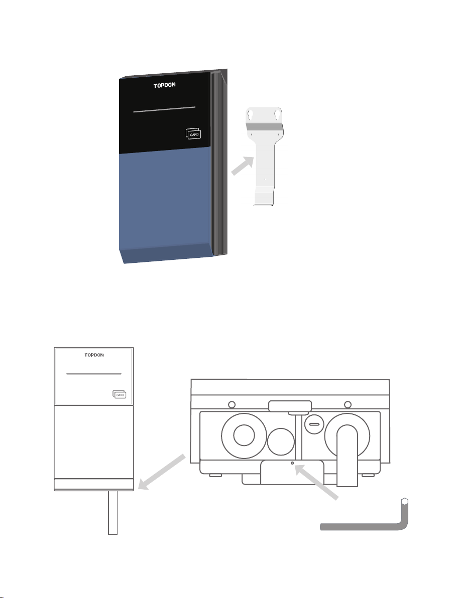
6. Attach the charger to the bracket. (See Fig. 5-8)
7. Fix the charger to the bracket with the hexagon socket head screw included in the
package, using the provided hex screwdriver. (See Fig. 5-9)
Fig. 5-8
Fig. 5-9
This manual suits for next models
3
Table of contents
Other Topdon Batteries Charger manuals

Topdon
Topdon Tornado 30000 User manual

Topdon
Topdon TB6000Pro User manual

Topdon
Topdon TB8000 User manual

Topdon
Topdon Tornado4000 User manual

Topdon
Topdon PulseQ AC Home US Version User manual

Topdon
Topdon TORNADO 90000 User manual

Topdon
Topdon TB6000Pro User manual

Topdon
Topdon Tornado 30000 User manual

Topdon
Topdon Tornado1200 User manual

Topdon
Topdon Tornado4000 User manual


