P.O. Box 1306, Newport Beach, California 92663 • Phone: 714-751-0488 • Fax: 714-957-1621 • E-Mail: techservice@newmarpower.com
www.newmarpower.com
4
PERSONAL PRECAUTIONS
1. Someone should be within range of your voice or close enough
to come to your aid when you work near a lead-acid battery.
2. Have plenty of fresh water and soap nearby in case battery
acid contacts skin, clothing or eyes.
3. Wear complete eye protection and clothing protection. Avoid
touching your eyes while working near a battery.
4. If battery acid contacts skin or clothing, wash immediately with
soap and water. If battery acid enters the eye, immediately flood
the eye with running cold water for at least 10 minutes and get
medical attention immediately.
5. NEVER smoke or allow a spark or flame in the vicinity of the
battery or engine.
6. Be extra cautious to reduce the risk of dropping a metal tool
onto the battery. It might spark or short-circuit the battery or other
electrical part and cause an explosion.
7. Remove personal metal items such as rings, bracelets, necklaces
and watches when working with a lead-acid battery. A lead-acid
battery can produce a short-circuit current high enough to weld a
ring or the like to metal, causing a severe burn.
8. Use the battery charger for charging gel-cell, AGM or flooded
lead-acid batteries only. It is not intended to supply power to a low
voltage electrical system other than in a starter-motor application.
Do not use the charger for charging dry-cell batteries that are
commonly used with home appliances. These batteries may burst
and cause injury to persons and damage to property.
9. NEVER charge a frozen battery.
PREPARING TO CHARGE
1. Be sure the area around the battery is well ventilated.
2. Clean battery terminals. Be careful to keep corrosion from
coming in contact with eyes.
3. Add distilled water in each cell until battery acid reaches level
specified by battery manufacturer. This helps purge excessive gas
from cells. Do not overfill. For a battery without cell caps, carefully
follow manufacturer’s recharging instructions.
4. Study all battery manufacturers’ specific precautions such
as removing or not removing cell caps while charging and
recommended rates of charge.
GROUNDING AND A.C. POWER CORD CONNECTION
1. The charger should be grounded to reduce the risk of electric
shock.
(For marine applications only) EXTERNAL CONNECTIONS TO THE
CHARGER SHALL COMPLY WITH UL RECOMMENDATIONS AND/
OR UNITED STATES COAST GUARD ELECTRICAL REGULATIONS
(33CFR183, SUB-PART I)
(For marine applications only) THE INSTALLATION AND
PROTECTION OF VESSEL WIRING ASSOCIATED WITH BATTERY
CHARGERS SHALL COMPLY WITH ABYC STANDARDS; E-11) AC
& DC ELECTRICAL SYSTEMS ON BOATS, AND A-31) BATTERY
CHARGERS & INVERTERS.
III) INSTALLATION
A) Materials Provided
1) Installation/Operation manual
1) Clear plastic output terminal cover
The Phase Three charger is provided completely assembled and
ready for installation. The installer must provide four suitable 1/4”
mounting screws/washers, as well as D.C. output wiring and
connectors. Proper sizes and gauges for the wire and connectors
are noted in section III-D following.
B) Location
The charger should be mounted on a wall, bulkhead or other
suitable mounting surface as close to the batteries to be charged
as possible. Do not mount the charger directly over the batteries
as battery fumes may cause excessive corrosion. WARNING:
The charger is not ignition protected so it must not be located
in an area where ignition protected equipment is required. The
area should be well ventilated and free from excessive moisture,
exhaust manifolds and battery fumes.
Vertical mounting is preferred. However, horizontal mounting is
acceptable where absolutely necessary. Do not mount the charger
where water, spray or condensation can occur, as this will shorten
charger life. It should not be located where there is a possibility
of dust or debris being drawn into the unit through the fan. A
minimum of 2” clearance around the charger is recommended for
proper cooling.
If the charger is located in an extreme heat area, such as an
unventilated engine room, and maximum operating temperature
is exceeded, an automatic thermal shutdown protection circuit
will turn the charger completely off. Thermal cycling will shorten
the life of the charger, so if this condition occurs repeatedly, the
charger should be relocated. For optimum performance and
longer life the charger should not be located in an area of extreme
high temperature.
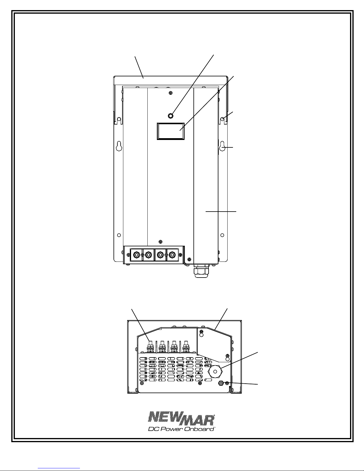
C) Mounting
Important Pre-Installation Note: The wiring access port for A.C.
input is located on the bottom of the charger. If the factory-installed
A.C. cord must be changed for any reason, this should be done
before mounting, as access will be difficult afterwards. Also, the
drip shield will need to be removed prior to setting the gel/lead
acid selector or installing the optional temperature compensation
probe. The drip shield is removable with the charger mounted,
but if there is limited overhead clearance, the installer may wish
to accomplish these tasks also, prior to mounting the charger. For
information on these installation procedures, refer to sections III-F
and IV-E.
The charger may be mounted on either a metal or non-metal
surface*. You will require four screws (wood or machine screws,
depending on mounting surface) with washers, sized for 1/4”
holes, to mount the charger, plus two temporary holding screws.
Note that, in addition to the four permanent mounting holes in the
flanges, there is a hole in each mounting flange which is “keyhole”
shaped. This is provided to ease vertical installation.