Topdon T-Ninja Box User manual

www.topdon.com I
FCC Warnning:
Any Changes or modifications not expressly approved by the party responsi-
ble for compliance could void the user's authority to operate the equipment.
This device complies with part 15 of the FCC Rules. Operation is subject to
the following two conditions:
(1) This device may not cause harmful interference.
(2) this device must accept any interference received, including interference
that may cause undesired operation.
Note: This equipment has been tested and found to comply with the limits for
a Class B digital device, pursuant to part 15 of the FCC Rules. These limits
are designed to provide reasonable protection against harmful interference
in a residential installation. This equipment generates uses and can radiate
radio frequency energy and, if not installed and used in accordance with the
instructions, may cause harmful interference to radio communications. How-
ever, there is no guarantee that interference will not occur in a particular
installation. If this equipment does cause harmful interference to radio or
television reception, which can be determined by turning the equipment off
and on, the user is encouraged to try to correct the interference by one or
more of the following measures:
- Reorient or relocate the receiving antenna.
Copyright
Copyright © 2021 by TOPDON TECHNOLOGY CO., LTD. All rights reserved.
No part of this publication may be reproduced, stored, or transmitted in any
form without the written permission of the copyright owner.
Trademark
TOPDON is a registered trademark of TOPDON TECHNOLOGY CO., LTD in
China and other countries. All other marks are trademarks or registered trade-
marks of their respective owners.
Disclaimer
The contents of this document are subject to changes without notice due
to continued improvements in design, manufacture, and methodologies.
TOPDON is not liable for the damage or losses due to the use of this docu-
ment.

www.topdon.com
II
- Increase the separation between the equipment and receiver.
- Connect the equipment into an outlet on a circuit different from that to
which the receiver is connected.
- Consult the dealer or an experienced radio/TV technician for help.
The device has been evaluated to meet general RF exposure requirement.
The device can be used in portable exposure condition without restriction.
ISED Warnning:
This device contains licence-exempt transmitter(s)/receiver(s) that comply
with Innovation, Science and Economic Development Canada’s licence-ex-
empt RSS(s). Operation is subject to the following two conditions:
(1) This device may not cause interference.
(2) This device must accept any interference, including interference that may
cause undesired operation of the device.
L'émetteur/récepteur exempt de licence contenu dans le présent appareil est
conforme aux
CNR d'Innovation, Sciences et Développement économique Canada applica-
bles aux appareils radio exempts de licence. L'exploitation est autorisée aux
deux conditions suivantes :
1) L'appareil ne doit pas produire de brouillage;
2) L'appareil doit accepter tout brouillage radioélectrique subi, même si le
brouillage est susceptible d'en compromettre le fonctionnement.
This transmitter must not be co-located or operating in conjunction with any
other antenna or transmitter. Cet émetteur ne doit pas être colocalisé ou
fonctionner en conjonction avec une autre antenne ou un autre émetteur.
The device has been evaluated to meet general RF exposure requirement.
The device can be used in portable exposure condition without restriction.
Le matériel a été évalué pour répondre aux exigences générales d’exposi-
tion aux radiofréquences.Le dispositif peut être utilisé dans des conditions d
‘exposition portables illimitées.

Important: Please read this manual carefully and understand the safety
precautions before performing any operation to this product.
Safety Grades
Symbol Usage
Danger
Indicates a hazardous situation which, if not
avoided, will result in death or serious injury to the
operator or to bystanders.
Warning
Indicates a hazardous situation which, if not
avoided, could result in possible injury to the
operator or to bystanders.
Caution
Indicates a hazardous situation which, if not
avoided, could result in serious equipment damage
or property losses.
Safety Precautions
• Never collide, throw, or puncture the test equipment, and avoid falling,
extruding and bending it.
• Do not insert foreign objects into or place heavy objects on your device.
Sensitive components inside might cause damage.
• Do not use the test equipment in exceptionally cold or hot, dusty, damp or
dry environments.
• In places using the test equipment may cause interference or generate a
• The test equipment is a sealed unit. There are no end-user serviceable
parts inside. All internal repairs must be done by an authorized repair facility
• Never place the test equipment into apparatus with strong electromagnetic
III
• Do not attempt to replace the internal rechargeable lithium battery. Contact
the dealer for factory replacement.
• Use the included battery and charger. Risk of explosion if the battery is
replaced with an incorrect type.
www.topdon.com
• Do not disconnect power abruptly when the test equipment is being
formatted or in process of uploading or downloading. Or else it may result
in program error.
• Do not disconnect battery or any wiring cables in the vehicle when the
ignition switch is on, as this could avoid damage to the sensors or the ECU.
• Do not place any magnetic objects near the ECU. Disconnect the power
supply tothe ECUbefore performingany welding operations on the vehicle.
• Use extreme caution when performing any operations near the ECU or
sensors. Ground yourself when you disassemble PROM, otherwise ECU
and sensors can be damaged by static electricity.
• When reconnecting the ECU harness connector, be sure it is attached
damaged.
Packing List
destinations, the accessories may vary. For details, please consult from the
local dealer or check the packing list supplied with this tool together.
• Main unit
• Power adaptor
• Main diagnostic cable
• The fourth-generation data acquisition cable
• The fourth-generation of EEPROM data acquisition cable(without
dismantling dashboard)
• BENCH mode cable
• MCU converter V1
• MCU converter V2
• MCU cable with multiple leads
• EEPROM chip adaptor
• Benz infrared analog acquisition key
IV
• MCU cable with multiple leads
• EEPROM converter
• User Manual
www.topdon.com
V
Table of Contents
1 About this Manual...................................................................................1
1.1 Target Reader......................................................................................1
1.2 Typographic Conventions ....................................................................1
1.3 Symbols...............................................................................................1
2 About
T-Ninja Box
................................................................................................ 2
2.1 Product Overview ................................................................................2
2.2 Power Source......................................................................................3
.......................................................................4
2.4 Accessories .........................................................................................4
3 Diagnostics.............................................................................................7
3.1 Common Operations ...........................................................................7
3.1.1 Establish Hardware Connection .......................................................7
3.1.2 Establish Wireless Connection.........................................................8
3.1.3 Perform Common Operations...........................................................8
3.2 Diagnostic Operations .........................................................................9
3.2.1 Key Programming.............................................................................9
3.2.2 Gear Box Programming..................................................................14
3.2.3 Engine Programming......................................................................18
4. Software Upgrade................................................................................25
5. Warranty...............................................................................................27
www.topdon.com

1
1 About this Manual
This manual introduces the basic information of T-Ninja Box and instruction on
the product usage. T-Ninja Box is a powerful anti-theft solution and an ideal
choice for professional repair shops and vehicle maintenance businesses.
It has achieved vehicle key, Engine and gearbox programming, featuring
powerful multiple parts reprogramming and wide range of vehicle coverage.
1.1 Target Reader
This document is intended for vehicle owners or repair technicians to perform
various diagnosticprocedures using T-Ninja Box; it assumesa basic knowledge
of vehicles.
1.2 Typographic Conventions
the following table:
Item Presentation Example
Cascading Menus ->
Parameter/value Bold Silde the WLAN switch to “ON”.
Variable/unfamiliar
term Italic Visit us by
UI control Bold On the Health Check screen, tap
Enter.
Message “” The “success” message appears.
1.3 Symbols
Following symbols are used in this document:
Symbol Usage
Note Widely used for any supplementary
information.
Tip Refers to easily overlooked tricks that is
necessary for a better user experience.
www.topdon.com
T-Ninja Box->Local Diagnosis
http://www.topdon.com

2
2 About T-Ninja Box
2.1 Product Overview
www.topdon.com

3
No. Part Name Description
1DB26 diagnostic connector To connect with all anti-theft
cables.
2Benz key slot To place Benz car key.
3Key slot To place car key for RF
defection.
4Key chip slot To place key chip.
5Power indicator
• Red light indicates faults.
• Orange light indicates
normal operation.
6Valve To tighten loose EEPROM board.
7EEPROM slot To insert EEPROM board
DB15 diagnostic connector To connect with main diagnostic
cable.
DIY slot To insert vehicle DIY board.
Input voltage DC 12V
Input current 500 mA
Working temperature 0 to 50 ℃
Storage temperature - 20 to 70 ℃
Dimension 39 x 107 x 298 mm
www.topdon.com
Technical Specifications
9
8
4
2.3 Power Source
The product does not have an independent power supply, you can power it up
via either of the followings ways:
• Use the included power adaptor
• Connect the device through the vehicle’s DLC
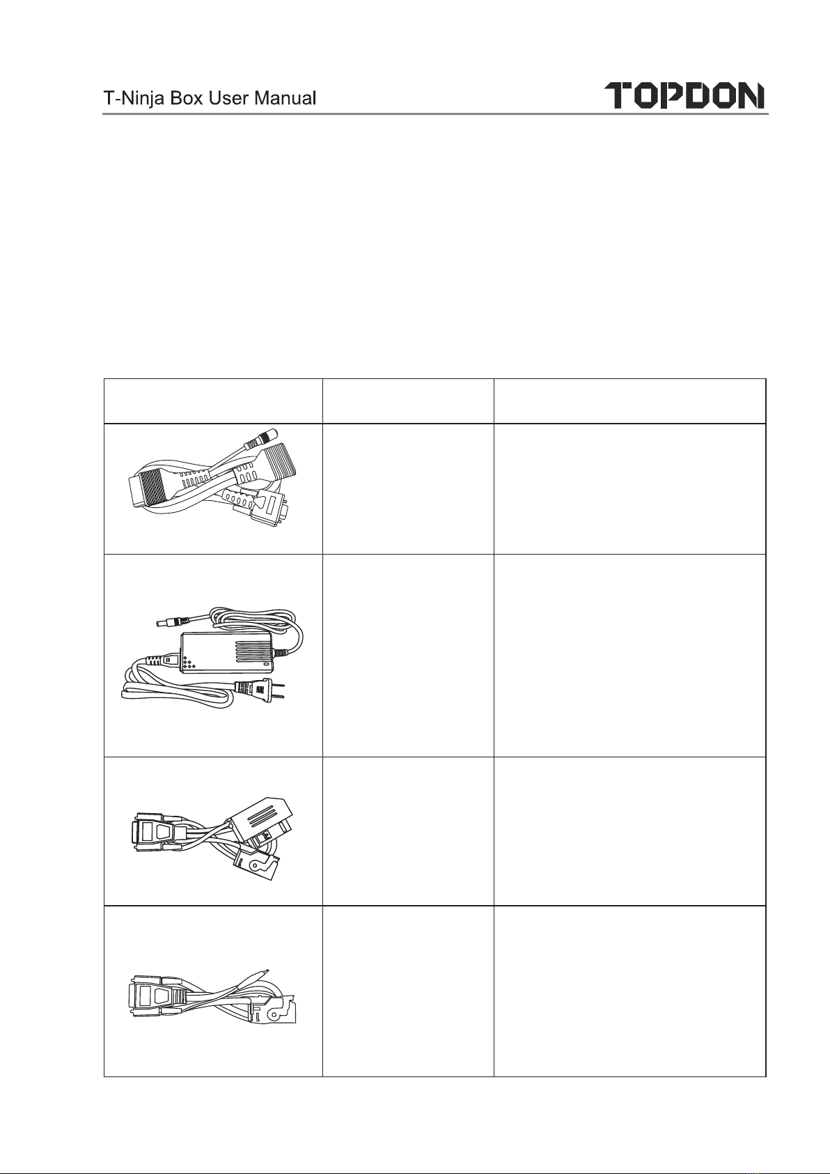
2.4 Accessories
Photo Accessory Name Description
To connect vehicle DLC port,
VCI and programmer for
diagnosis.
Power adaptor To provide power supply for
the programmer.
The fourth-
generation data
acquisition cable
After removing the vehicle
dashboard, connect
programmer, vehicle
dashboard, and the cable.
The fourth
generation of
EEPROM data
acquisition
cable (without
dismantling
dashboard)
Connect the programmer and
vehicle dashboard,and then
place the probe(the yellow
lead) to the designated area.
www.topdon.com
Main diagnostic
cable
5
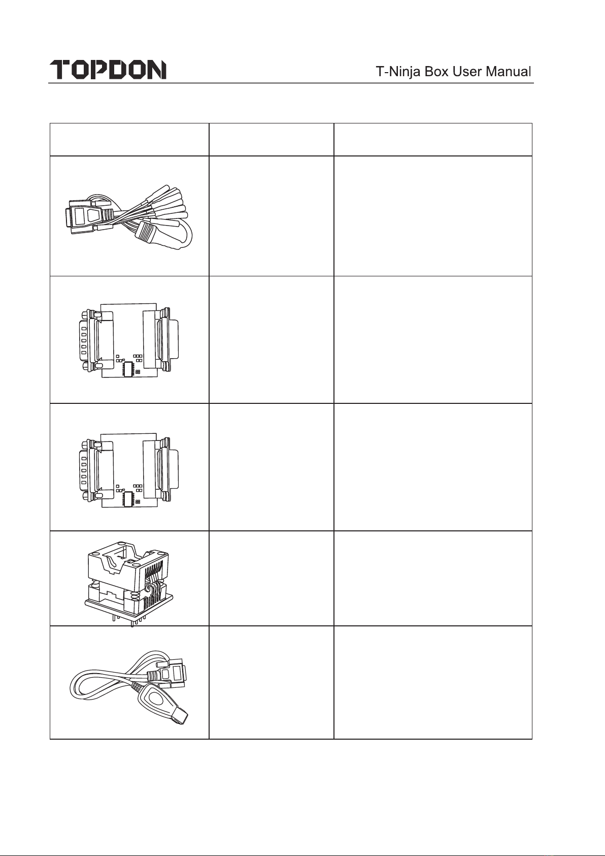
BENCH mode
cable
Connect the programmer and
the engine to read engine or
gearbox ECU (Connect engine
ECU with the BENCH mode
cable based on BENCH mode
diagram).
MCU Converter
V1
Connect the programmer
with MCU(chip soldering is
required in this procedure).
MCU Converter
V2
Connect the programmer
with MCU(chip soldering is
required in this procedure).
EEPROM chip
adaptor
Place the EEFROM chip onto
the adaptor, and then plug it
into the programmer socket.
Benz infrared
analog acquisition
key
To connect the programmer
with the key lock, insert the
key into the programmer for
further key operations.
www.topdon.com
Photo Accessory Name Description

6
www.topdon.com
MCU cable with
multiple leads
To connect the programmer
and MCU.
EEPROM
converter
Solder the desired chip on
the EEPROM converter, and
then plug the board into the
programmer(chip soldering is
required)
Photo Accessory Name Description
7
3 Diagnostics
3.1 Common Operations
• 3.1.1 Establish Hardware Connection
You need to turn off the ignition and correctly locate the vehicle Data Link
Connector (DLC) so as to perform hardware connection.
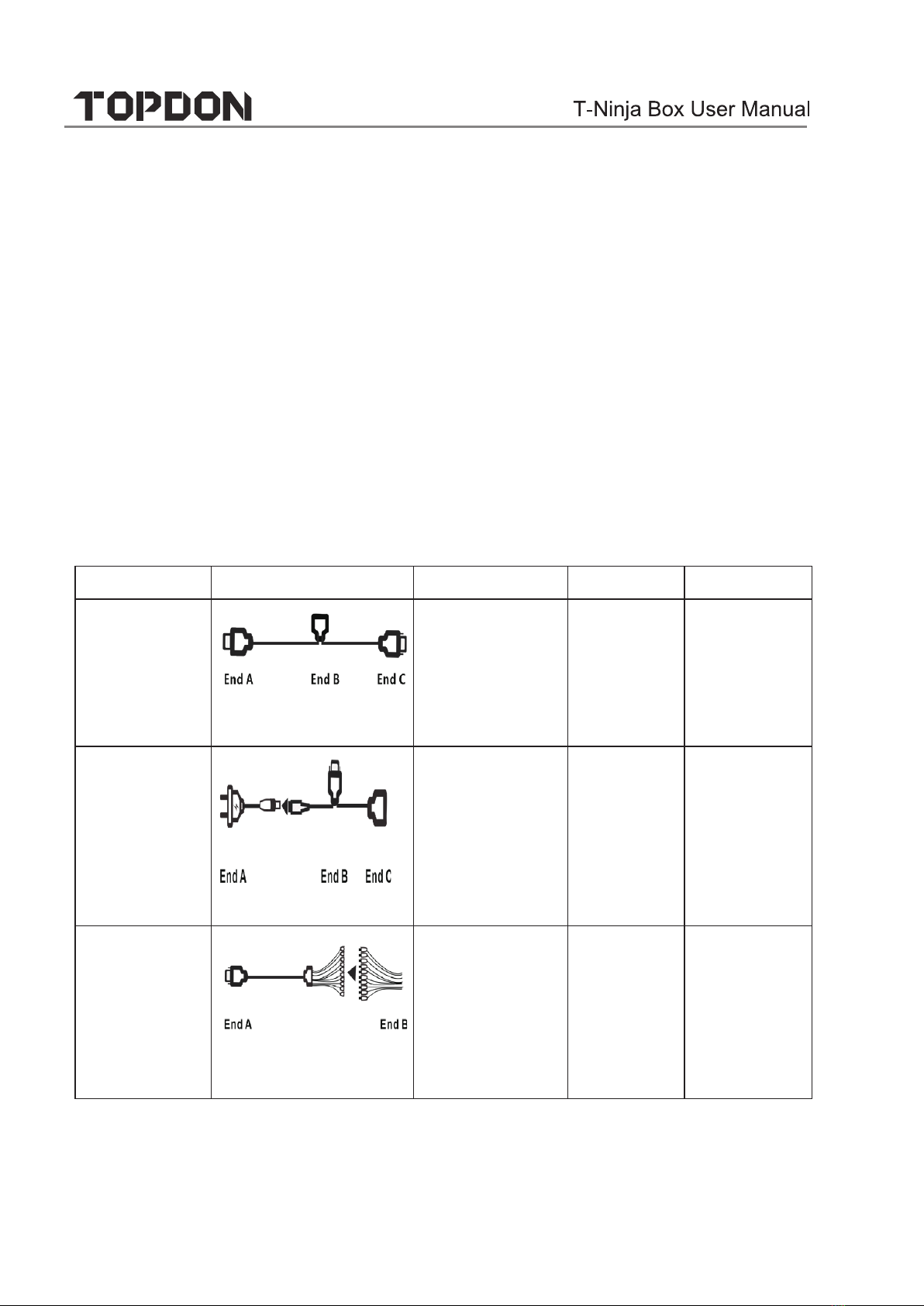
You can refer to the table below for hardware connection:
User Scenario Cable Image End A End B End C
Key
programming
Main diagnostic cable
Connect with
TOPDON VCI
connector
for data
transmission
Connect
with
vehicle’s
DLC
Connect with
T-Ninja Box
Engine/
Gearbox
programming
Power cable
Connect to
power supply N/A
Engine/
Gearbox
programming
MCU cable with
mutiple leads
Connect with
T-Ninja Box
Connect
with the
engine or
gearbox to
be repaired/
replaced
N/A
www.topdon.com
T-Ninja Box diagnosticfunction supports key programming, engine and gear-
box replacement for various of vehicles, you can retrieve ECU information,
read, erase, and write in for a range of chips as shown in the product options.
Connect to
end B of
the main
diagnostic
cable

8
Engine/
Gearbox
programming
Main diagnostic cable
Connect with
TOPDON VCI
connector
for data
transmission
Connect to
power
supply
cable
Connect with
T-Ninja Box
• 3.1.2 Establish Wireless Connection
You must make sure that your diagnostic tool is well connected with T-Ninja
Box, and follow steps below to check wireless connection:
Note: It is strongly recommended to connect the diagnostic tool with the
1. Slide down the status bar from the top.
2. Tap , go to Wireless and network -> Bluetooth.
3. Select the T-Ninja Box to be connected, wait until the connection is
successful.
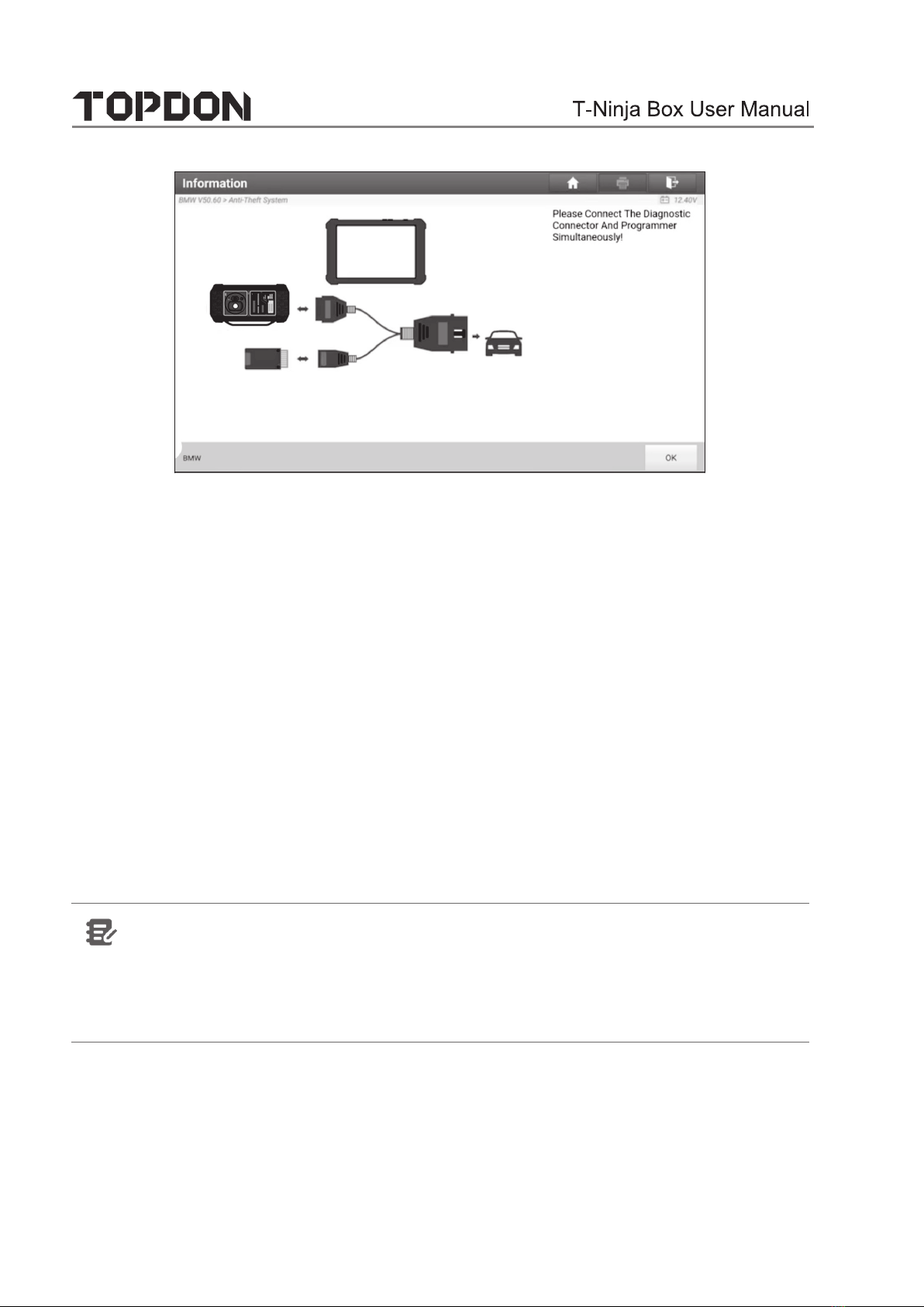
• 3.1.3 Perform Common Operations
You should enter the function interface before using the programmer.
1. Turn on a TOPDON diagnostic tool, and/or open the diagnostic App on the
home screen.
2. On the main diagnostic screen, enter Anti-theft system either from Local
Diagnose or Reset, tap OK.
3. You will view the connection diagram, tap OK.
www.topdon.com
4. Depending on your requirement, select any of the following options :
• Gearbox Learning
• Anti-Theft System
• Engine System
3.2 Diagnostic Operations
• 3.2.1 Key Programming
You can use anti-theft system to access key chip programming functions. The
product supports reading, retrieving and writing key information, as well as
other key-related functions.
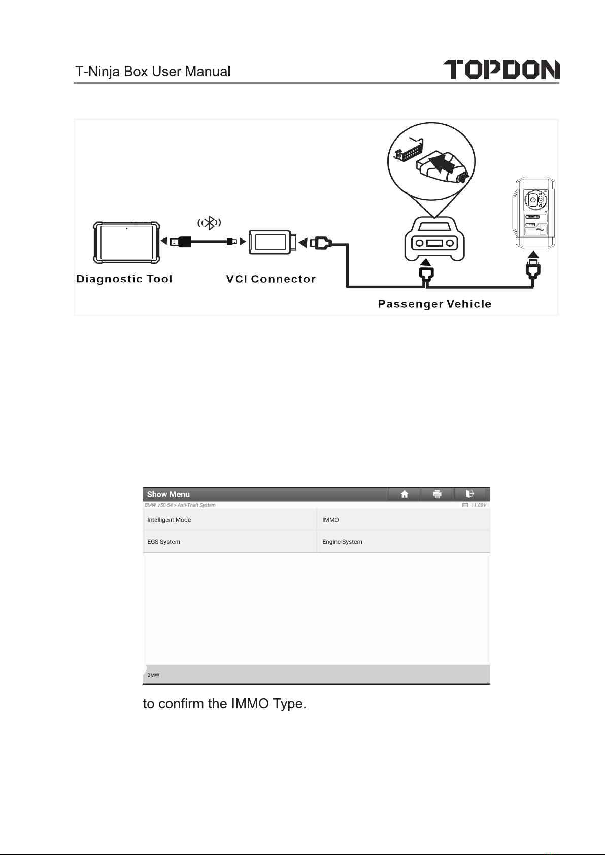
• Set up the Connections
Note:
www.topdon.com
9
The USB cable shown in the following diagram is not included in
the packing list for now, nevertheless, using a USB cable
could effectively enhance your data transmission speed.
10
• Operating on key programming
You can use key programming function to backup old key data and write
in data for new keys. Below procedure shows you how to perform key
TOPDON diagnostic product. It contains backupgnisuWMBrofgnimmargorp
current key data and new key generation.
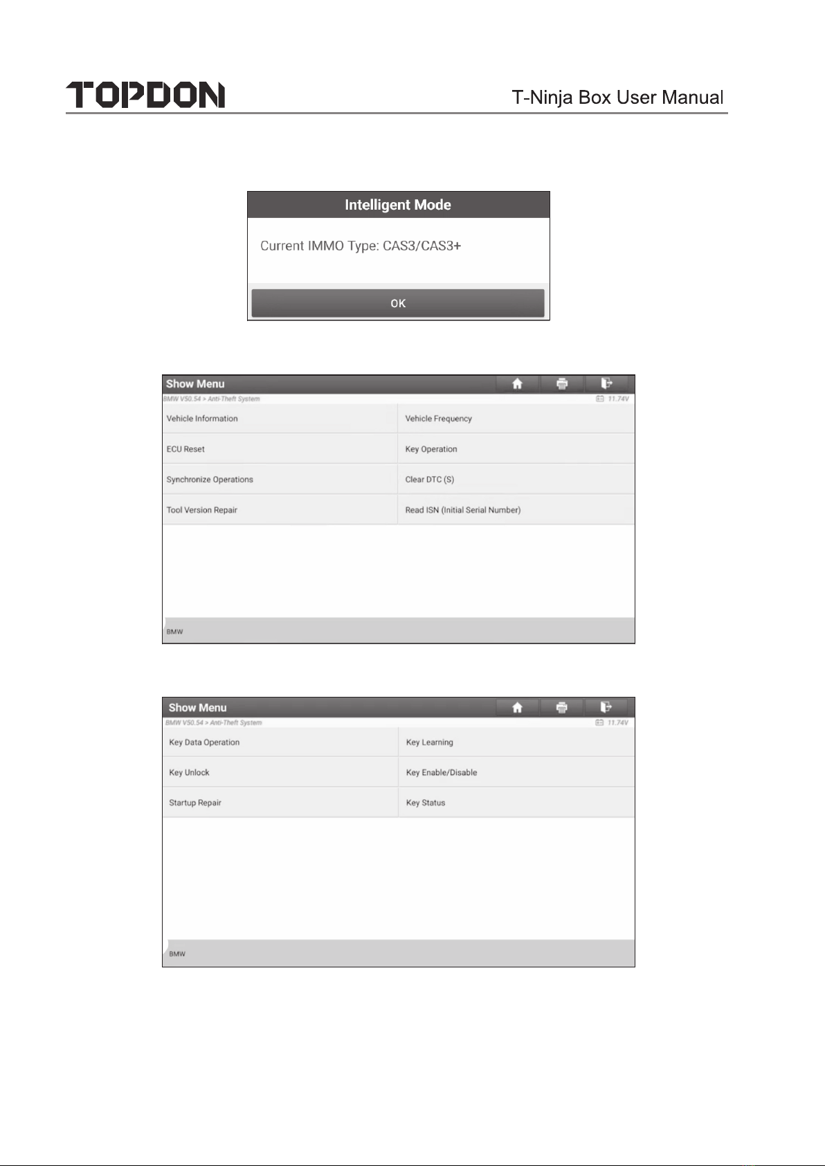
1. Backup current key data.
a. Select Intelligent Mode.
b. Tap OK
www.topdon.com
11
c. Select Key Operation.
d.
Select
Key Learning.
e. Tap OK after reading the onscreen instruction.
www.topdon.com

12
f. Tap OK.
g. Tap OK to save the key data.
h. OK.
i. OK
www.topdon.com

13
2. Generate a new key.
a. Select the desired blank key position.
b. Place the new key into the programmer key slot and tap OK.
c. YES.
d. If the key generation is done, tap OK t
www.topdon.com

14
• 3.2.2 Gearbox Programming
You can use gearbox programming function to restore the old gearbox data or
write in new data after a new gearbox is replaced.
• Set up the Connections for Gearbox Programming
Note:
•
• Certain vehicle gearboxes are connected based on the real chassis
type. For information on how to connect to a gearbox, refer to the
onscreen connection diagram.
• Operating on gearbox programming
www.topdon.com
The following procedure shows you how to perform gearbox programming for
a BMW using TOPDON diagnostic product, which contains gearbox connec-
tion and erasure of gearbox data.
The USB cable shown in the following diagram is not included in the
packing list for now, nevertheless, using a USB cable could effec-
tively enhance your data transmission speed.

15
1. Connecting to the gearbox.
a.
b. Select the correct chassis type.
c. You will then see a corresponding connection diagram. Tap OK.
www.topdon.com
On the programmer function interface, select EGS System to enter gear-
box programming.
Table of contents
Other Topdon Diagnostic Equipment manuals

Topdon
Topdon Phoenix Plus User manual

Topdon
Topdon Topscan Instruction manual

Topdon
Topdon ArtiDiag800 User manual

Topdon
Topdon ArtiDiag800 User manual

Topdon
Topdon Phoenix Lite 2 User manual

Topdon
Topdon Phoenix Pro User manual

Topdon
Topdon Phoenix Elite User manual

Topdon
Topdon ArtiLink 500 Technical manual

Topdon
Topdon ArtiDiag900 BT User manual

Topdon
Topdon ArtiDiag600 S User manual


