Topens MultiRuta CASAR 800 User manual
GARAGE DOOR OPENER
User’s Manual
Model:
CASAR 800
www.topens.com
Email: s[email protected]
★
Please read and follow all warnings, precautions and instructions before
installation and use.
★Save this manual.
C030554
VER 21a
TOPENS Website

CONTACT US:
Visit: www.topens.com
Please record the product model, your email address etc.
in the spaces provided below. Refer to this list when contacting TOPENS
for technical service or assistance with your automatic gate opener.
Where did you purchase? (Amazon.com; Amazon.ca: Amazon.co.uk, Amazon.de; Other, Please
Specify)
Order# Product Model Purchase Date
Full Name Phone# Email Address (VERY
IMPORTANT)
Street Address, Apartment /Unit, City, State /Province, Zip Code Country/Region
Did you purchase any
accessories? (Please list
below)
Issue Details
Email Us: support@topens.com
Call: +1 (888) 750 9899 (Toll Free USA & Canada)

Table of Contents
1. Before You Begin ....................................................................................................................................... 4
1.1 Door Types ......................................................................................................................................................4
1.2 Tools Required for Installation...................................................................................................................5
1.3 Accessories Connection .............................................................................................................................5
1.4 Completed Installation.................................................................................................................................6
2. ASSEMBLY SECTION................................................................................................................................. 7
2.1 Open the Chain Package.............................................................................................................................7
2.2 Assemble the Driving Assembly ...............................................................................................................7
2.3 Assemble the Rail..........................................................................................................................................7
2.4 Fasten Rail to Opener and Install Chain..................................................................................................8
2.5 Attach Sprocket Cover.................................................................................................................................9
2.6 Install Header Sleeve and Tighten Chain ................................................................................................9
3. INSTALLATION SECTION ........................................................................................................................ 10
3.1 Position the Header Bracket.....................................................................................................................10
3.2 Install the Header Bracket.........................................................................................................................11
3.3 Attach Rail to Header Bracket..................................................................................................................12
3.4 Position the Opener....................................................................................................................................12
3.5 Hang Opener.................................................................................................................................................13
3.6 Fasten Door Bracket...................................................................................................................................13
3.7Assemble Door Arm (NOT Bow Arm) ......................................................................................................14
3.8 Install Door Control (Optional).................................................................................................................15
3.9 Install the Safety Photocell Beam (SPB) System (Optional) ............................................................16
4. ADJUSTMENT SECTION.......................................................................................................................... 17
4.1 Learning the code. ......................................................................................................................................17
4.2 Setting the Limits ........................................................................................................................................18
4.3 Setting the Open Force..............................................................................................................................19
4.4 Setting the Close Force .............................................................................................................................19
4.5 Setting the Automatic Closing Time.......................................................................................................20
4.6 Set the Safety Photocell Beam (SPB) System (Optional) .................................................................20
4.7 Test the Safety Reverse System
(
Very Important
)
..........................................................................21
4.8 Wireless Keypad Programming (Optional)...........................................................................................21
4.9 Install HLR01 HomeLink Remote Control Kit (Optional)...................................................................22
4.10 Light Features............................................................................................................................................22
4.11 Trouble Shooting.......................................................................................................................................22
4.12 Care of Your Opener.................................................................................................................................24
4.13 Maintenance of Your Opener..................................................................................................................24
5. Quick-Setting Guide................................................................................................................................. 25
5.1 Program your Opener & Remote.............................................................................................................25
5.2 To Erase all remote Control codes .........................................................................................................25
5.3 Unit Setting ...................................................................................................................................................26
1
Technical Specifications & Features
Specifications
Input Voltage: 110 - 120V/60Hz or 220 - 240V/50Hz
Motor Voltage: 24VDC
Light Power: 120V or 230V, 10-15W (subject to consumer area)
Operation Speed: 120mm/s(4.7 in/s)
Frequency: 433.92MHz
Standby Power: <8W
Rated Force:
300N
Max. Force:
800N
Headroom Required:
30mm (1.2 in)
Features:
·
Stop in case of obstruction during gate opening
·
Reverse in case of obstruction during gate closing
·
Soft start and soft stop (each soft period can Not be adjusted).
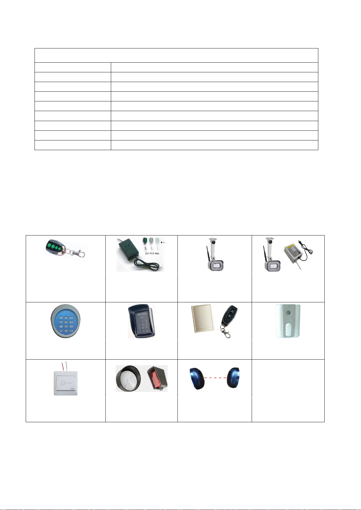
Optional Accessories Parts List (Available at TOPENS
Store)
M12 Remote Control ERM12 External
Receiver
TC186-R WiFi
Smartphone Remote
Control with Camera
TC186 WiFi
Smartphone Remote
Control with Camera
TKP3 Wireless Keypad TC175P Wired Keypad HLR01 HomeLink
Remote Control Kit
TC173 Wireless Push
Button
TC147 Wired Push
Button
TRF3 Reflection
Photocell Sensor
TC102 Photo Eye
Beam Sensor

2
Replacement Parts
CKMJ2A Control Board
WARNING: Changes or modifications not expressly specified by this user manual, TOPENS could void
the warranty of this equipment.

3
Start by Reading These Important Safety Rules
These safety alert symbols mean WARNING-a personal safety or property damage instruction.
Read these instructions carefully.
This garage door opener is designed and tested to offer reasonable safe service provided it is installed and
operated in strict accordance with the following safety rules.
Failure to comply with the following instructions may result in serious personal injury or property damage.
The garage door opener is not intended for use by persons (including children) with reduced physical, sensory or mental
capabilities, or lack of experience and knowledge, unless they have been given supervision or instruction concerning use of
the appliance by a person responsible for this safety.
WARNING: If your garage has no service entrance door, an Outside Quick Release must be installed. This accessory allows
manual operation of the garage door from outside in case of power failure.
Keep garage door balanced. Sticking or binding
doors must be repaired. Garage doors, door springs,
cables, pulleys, brackets and their hardware are under
extreme tension and can cause serious personal injury. Do
not attempt to loosen, move or adjust them. Call for garage
door service.
Do not wear rings, watches, or loose clothing while
installing or servicing a garage door opener.
Before installing the garage door opener, remove all
unnecessary ropes or chains and disable any equipment,
such as locks, not needed for powered operation. Check
that the door is in good mechanical condition, correctly
balanced and opens and closes properly. Installation and
wiring must be in compliance with your local building and
electrical codes. Connect the power supply cord only to
properly earthed mains.
Lightweight doors of fiberglass, aluminum or steel
must be substantially reinforced to avoid door damage.
The best solution is to check with your garage door
manufacturer for an opener installation reinforcement kit.
Important safety instructions. Follow all instructions
since incorrect installation can lead to severe injury.
This unit should not be installed in a damp or wet
space.
After installation,
ensure that the mechanism is
properly adjusted and that the
opener reverses when the
door contacts a 100mm(4”
) high object placed on the floor.
Failure to properly adjust the opener may resu
lt in serious
personal injury from a closing garage door.
Each month
check that the opener reverses when the door contacts a
100mm (4”)
high object placed on the floor for opener
incorporating an entrapment protection system depending
on contact with the bottom edge of the door. Adjust if
necessary and recheck since an incorrect adjustment may
present a hazard.
After installation, ensure that parts of the door do
not extend over public footpaths or roads.
The opener must not be used with a door
incorporating a wicket door (unless the opener can not be
operated with the wicket door open.)
Frequently examine the installation, in particular check
cable, springs and mountings for signs of wear, damage or
imbalance. Do not use if repair of adjustment is needed since
a fault in the installation or an incorrectly balanced door may
cause injury.
Fasten the child warning label adjacent to the lighted
door control button as a reminder of safe operating
procedures.
Disengage all existing garage door locks to
avoid damage to garage door.
Install any fixed control at a height of at least 1.5m and
within sight of the door but away from moving parts and out
of the reach of children. Permanently fix the labels warning
against entrapment in a prominent place or near any fixed
controls. Children should be supervised to ensure that they
do not play with the appliance. Do not allow children to play
with door controls. Keep remote controls away from children.
Serious personal injury from a closing garage door may
result from misuse of the opener.
Activate opener ONLY when the door is in full view,
free of obstructions and opener is properly adjusted. No one
should enter or leave the garage while the door is in motion.
Do not allow children to play near the door.
Watch the
moving door and keep people away until the door is
completely opened or closed.
Install the actuating member for the manual release at
a height less than 1.8m.
Use manual release only to
disengage the trolley and, if possible, ONLY when the door is
closed. Do not use the red handle to pull the door open or
closed.
Take care when operating the manual release since
an open door may fall rapidly due to weak or broken springs
or being out of balance.
The opener
must not be used with a door having
opening exceeding 10 mm (0.4”) in diameter or having edges
or protruding parts a person could grip or stand on.
Disconnect the supply when cleaning or carrying out
other maintenance.
This product is provided with a transformer and power
supply cord of special design which, if damaged, MUST be
replaced by a transformer from your local distributor and
fitted by a specialist.
SAVE THESE INSTRUCTIONS

4
1. Before You Begin
Look at the wall or ceiling above the garage door. The header bracket MUST be securely fastened
to structural supports. It is easier to fit this door opener while the garage door is in the colsed
position and before you set the control board.
Do you have a finished ceiling in your garage? If so, a support bracket and additional fastening
hardware (not supplied) may be required..
Do you have an access door in addition to the garage door? If not, an Outside Quick Release
Accessory is required.
1.1 Door Types
Max. Door Height: 7.5 feet (2.3 m)
Max. Door Area: 129.2 ft² (12 m²)
5
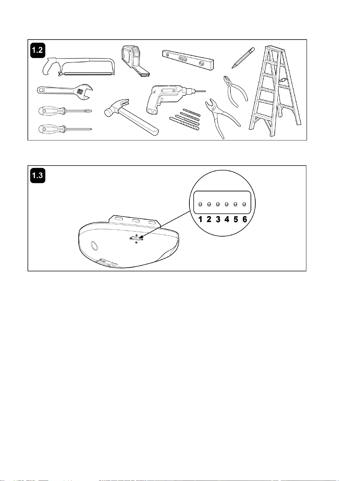
1.2 Tools Required for Installation
1.3 Accessories Connection
There is Connecting Wire Terminal in the unit’s side as picture 3, the function is as follows:
Terminal 1 for DOOR CONTROL BUTTON
Terminal 2 for DOOR CONTROL BUTTON
Terminal 3 for SAFETY PHOTOCELL BEAM (SPB)
Terminal 4 for SAFETY PHOTOCELL BEAM (SPB)
Terminal 5 for positive of Additional 24VDC Power Source
Terminal 6 for negative of Additional 24VDC Power Source
NOTE: The output current of port 5 and 6 is less than 100mA.
6
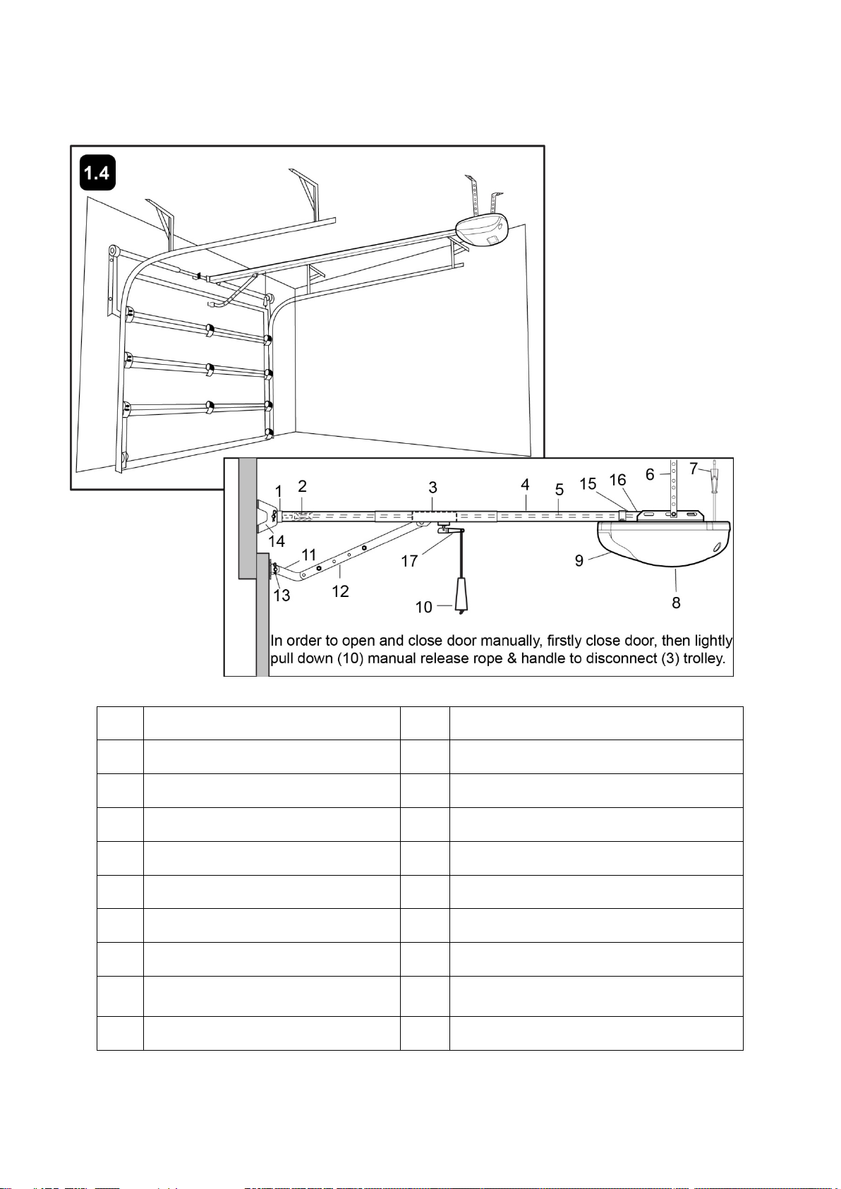
1.4 Completed Installation
As you proceed with the assembly, installation and adjustment procedures in this manual, you may find it
helpful to refer back to this illustration of a completed installation.
NO. Name NO. Name
1 Header Sleeve 10 Manual Release Rope & Handle
2 Idler Pulley Bracket 11 Curved Door Arm
3
Trolley
12 Straight Door Arm
4 Rail 13 Door Bracket & Plate
5 Chain 14 Header Bracket
6 Hanging Bracket 15 Driving Wheel
7 Power Cord 16 Wheel Base
8 Opener 17 Rope’s Lever
9 Light Lens
7
2. ASSEMBLY SECTION
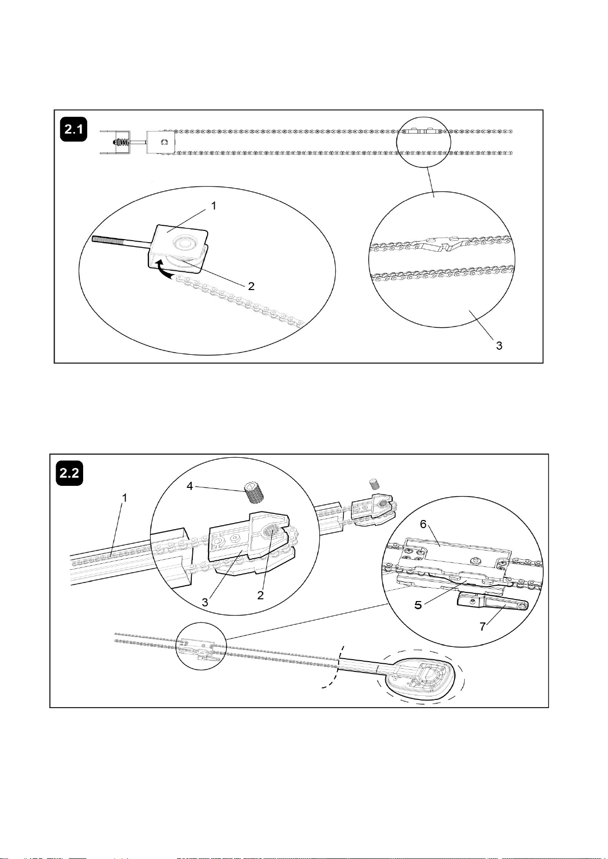
2.1 Open the Chain Package
Drill the one end of chain through the space between the pulley bracket (1) and Idler pulley (2), wrapping it
round the idler pulley (2). Then connect live knots in both ends of the Chain to both ends of the chain
connector (3). Finally push Idler pulley bracket (1) into the rail section which is with holes.
2.2 Assemble the Driving Assembly
The driving assembly (consisting of driving wheel (2), wheel base (3) and splined sleeve (4)) has been well
assembled in the factory. Assemble the Chain in each end of the trolley (6), and then put them in the rail.
Trolley (6) and chain connector (5) should lock together.
NOTE: Rope’s lever (7) should be toward the door opener unit.
Wrap the chain round the driving wheel (2), and push the driving assembly into the rail.
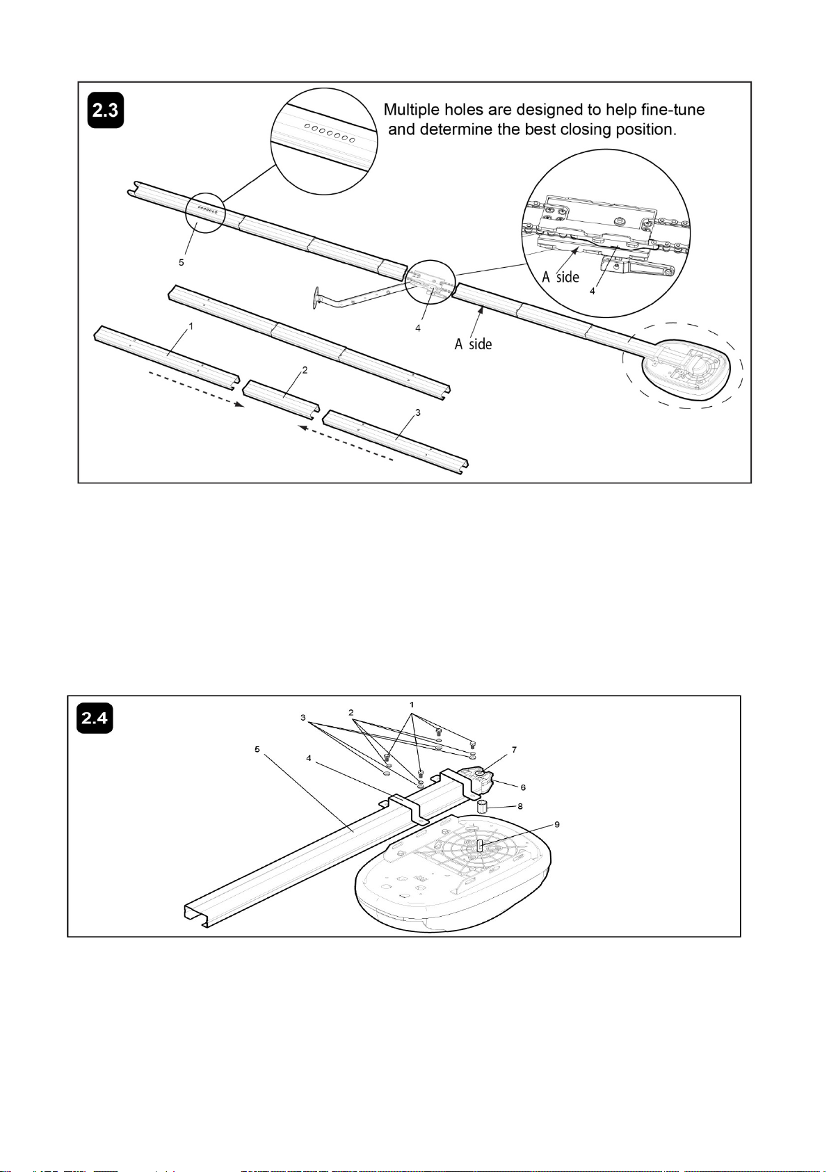
2.3 Assemble the Rail
8
Wear protective gloves when assemble the rail to protect your hands from possible injury from the edge of
the rail.
Place rail pieces (1) on flat surface for assembly. All four rail sections are interchangeable. Slide rail brace (2)
onto rail section. Connect rail by sliding rail brace onto next rail section. Tap rail assembly on piece of wood
until rail sections are flush. Repeat with remaining rail sections. Please check whether the chain connector
(4) is on the A side as picture shows.
NOTE: Check if the rail section with holes (5) is in the farthest end from the opener.
2.4 Fasten Rail to Opener and Install Chain
Insert four bolts (1) into the holes of brackets (4), secure with elastic washer (2) and washer (3). Place rail (5)
on opener. Wrap chain (6) over sprocket (7). Push idler pulley bracket assembly toward front of the rail to
eliminate excess slack in chain. Insert the splined sleeve (8) into sprocket (7). Put the splined sleeve (8)
onto the output shaft (9). Align bolt holes on brackets (4) with bolt holes on opener. Secure brackets to
opener with previously removed bolts. Tighten bolts securely. The opener sprocket teeth must engage the
chain.
CAUTION: Use only those bolts mounted in the top of opener. Use of any other bolts will cause serious
9
damage to opener.
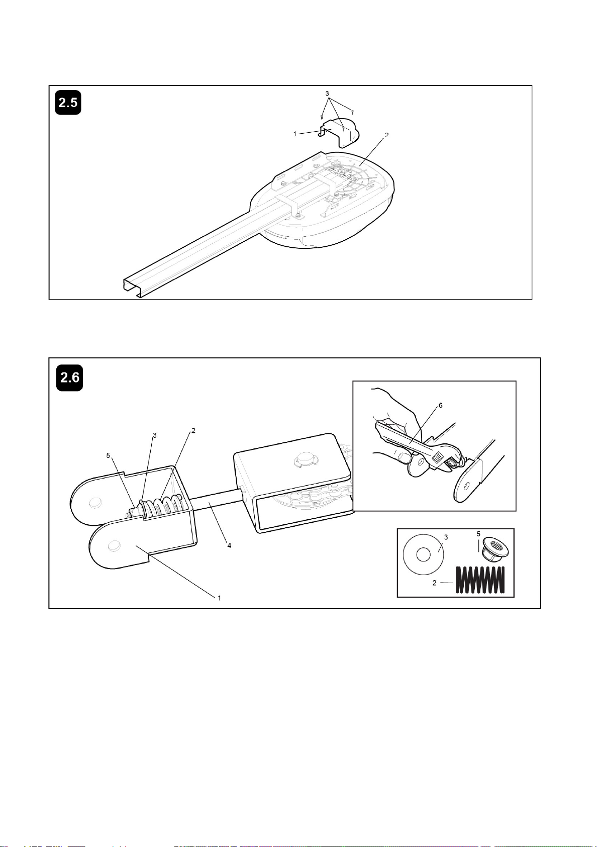
2.5 Attach Sprocket Cover
Place sprocket cover (1) on top of the opener (2), secure with screws (3).
2.6 Install Header Sleeve and Tighten Chain
Slide header sleeve (1) onto rail. Slide flat washer (3), spring (2) and washer (3) onto carriage bolt (4).
Thread nut (5) onto carriage bolt until finger tight. Use an open end wrench (6) to tighten nut until the chain is
not against the inside surface of the rail.
ASSEMBLY
OF
YOUR
OPENER
IS
NOW
COMPLETE.

10
3. INSTALLATION SECTION
Wear protective goggles when working overhead to protect your eyes from injury.
Disengage all existing garage door locks to avoid damage to garage door. To avoid serious
personal injury from entanglement, remove all ropes connected to garage door before installing
opener.
Installation of this product shall comply with ZH1/494, VDE 0700 Part 238, and VDE 0700 Part 1. It
is recommended that the opener be installed 2.1m (7 feet) or more above the floor where space
permits.
3.1 Position the Header Bracket
The
header
bracket
must
be
rigidly
fastened
to
a
structural
support
of
the
garage.
Reinforce
the
wall
or
ceiling
with
a
40
mm
(1-1/2")
board
if
necessary
.
Failure
to
comply
may
result
in
improper
operation
of
safety
reverse
system.
You can attach the header bracket either to the header wall (1) or to the ceiling (3). Follow the instructions
which will work best for your particular requirements.
With the door closed, mark the vertical centerline (2) of the garage door. Extend line onto header wall above
the door.
Open door to highest point of travel. Draw an intersecting horizontal line (4) on header wall 5 cm (2") above
high point to provide travel clearance for top edge of door.
11
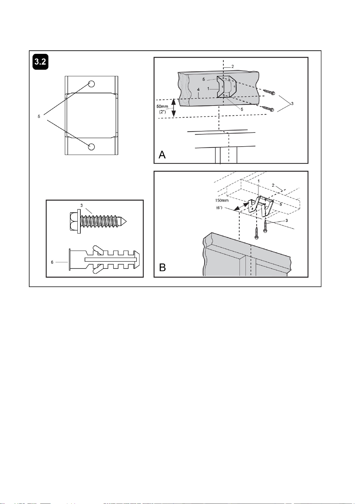
3.2 Install the Header Bracket
NOTE:
Refer
to
vertical
center
and
horizontal
lines
created
in
step
10
for
proper
placement
of
header
bracket.
A. Wall Mount: Center the header bracket (1) on the vertical center line (2) with the bottom edge of the
header bracket on the horizontal line (4) (with the arrow pointing toward the ceiling). Mark all of the header
bracket holes (5). Drill 4.5 mm (3/16") pilot holes and fasten the header bracket with wood screws (3).
B. Ceiling Mount: Extend vertical center line (2) onto the ceiling. Center the header bracket (1) on the
vertical mark no more than 150 mm (6") from the wall. Make sure the arrow is pointing toward the opener.
Mark all of the header bracket holes (5). Drill 4.5 mm (3/16") pilot holes and fasten the header bracket with
wood screws (3). For concrete ceiling mount, use concrete anchors (6) provided.
12
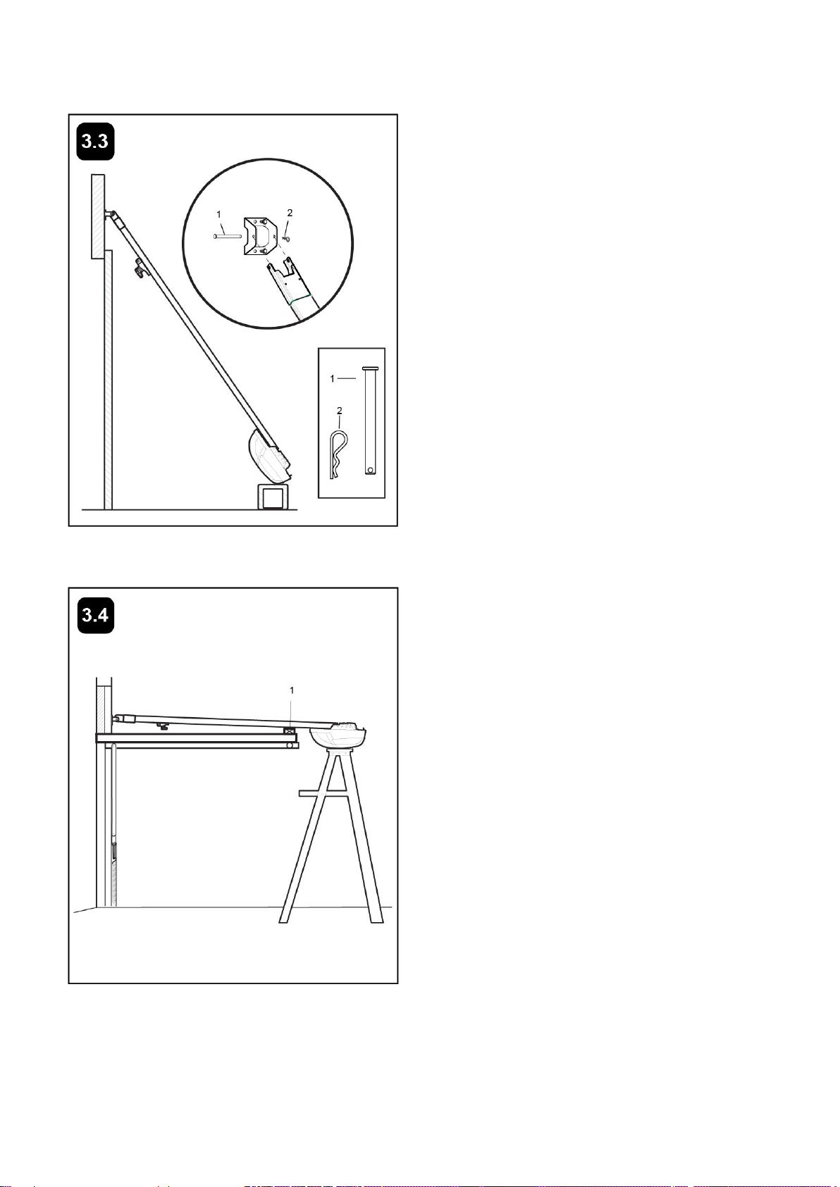
3.3 Attach Rail to Header Bracket
3.4 Position the Opener
Position opener on garage floor below the
header bracket. Use packing material to
protect the cover. Raise rail until holes in the
header sleeve and holes in the header
bracket align. Join with clevis pin (1). Insert
“R” pin (2) to secure.
NOTE:
T
o
enable
the
rail
to
clear
sectional
door
springs,
it
may
be
necessary
to
lif
t
opener
onto
a
temporary
support.
The
opener
must
either
be
secured
to
a
support
or
held
firmly
in
place
by
another
person.
Raise the opener onto a stepladder. Open
garage door. Place a 25mm (1") board (1)
laid flat on the top section of door near the
centerline as shown. Rest the rail on the
board.
If the raised door hits the trolley, pull down on
the trolley release arm to disconnect the
inner and outer trolley sections. The trolley
can remain disconnected until connecting
door arm to trolley is completed.
NOTE:
A
25mm
(1")
board
(1)
is
convenient
for
setting
an
ideal
door
-to-rail
dist
ance
(unless
headroom
is
not
sufficient).

13
3.5 Hang Opener
Bend Hanging Brackets (1) so they are flat against ceiling. Measure distance from Header Bracket to Ceiling
Mounting Bracket Bolts (4). Mark length on ceiling starting at the Header Wall, along this point is where the
unit will be mounted. Lift door to full open position, rest opener on door. Slide Hanging Brackets on to Ceiling
Mounting Bracket Bolts (4) on the opener. Secure Brackets with Nut (5). For concrete ceilings, drill 8mm(0.3”)
pilot holes into ceiling and insert Concrete Anchors (2). Secure Hanging Brackets to ceiling with Lag Screws
(3). For wood ceilings, drill 4mm(0.16”) pilot holes and secure with Lag Screws (3).
3.6 Fasten Door Bracket
If you have a canopy garage door, a door arm conversion kit is required. Follow the installation instructions
included with the replacement door arm. Exercise care in removing and assembling arm conversion kit.
Keep fingers away from the sliding parts.
NOTE:
Horizont
al
and
vertical
reinforcement
is
needed
for
lightweight
garage
doors.

14
Sectional
and
One-Piece
Door
Installation
Procedure:
Door bracket has left and right side fastening holes. If your installation requires top and bottom fastening
holes use both the door bracket and door bracket plate as shown.
Center door bracket (with or without door bracket plate, as required) at the top inside face of door as shown.
Mark holes.
3.7Assemble Door Arm (NOT Bow Arm)
A.
ONE-PIECE
DOOR
INST
ALLA
TION:
Fasten the straight (1) and curved (2) door arm sections together to the longest possible length (with a 2 or 3
hole overlap) using hardware (3, 4 and 5). With the door closed connect the straight door arm section (1) to
the door bracket with clevis pin (6). Secure with “R” pin (7). Disconnect the inner and outer trolley. Slide the
outer trolley back toward the opener and join the curved arm (2) to the connector hole in the trolley (8) with
clevis pin (6). It may be necessary to lift the door slightly to make the connection. Secure with “R” pin (7).
NOTE:
When
setting
the
up
limit,
the
door
should
not
have
a
“backward”
slant
when
fully
open.
A
slight
backward
slant
(9)
will
cause
unnecessary
bucking
and/or
jerking
operation
as
the
door
is
being
opened
or
closed
from
the
fully
open
position.
B.
SECTIONAL
DOOR
INST
ALLA
TION:
Connect according to Figure B, and then proceed to Step A.
15
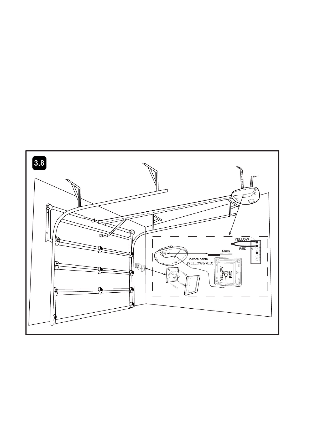
3.8 Install Door Control (Optional)
Locate door control where the garage door is visible, away from door and door hardware and out of the
reach of children. Mount at least 5 feet (1.5 meters) above the floor.
Serious personal injury from a moving garage door may result from misuse of opener. Do not allow children
to operate the door control or remote control transmitter.
Permanently fasten the caution label permanently to the wall near the door control as a reminder of safe
operating procedures.
Fasten the door control to an inside garage wall with sheet metal screws (not provided). A convenient place
is beside the service door and out of reach of children.
Use a 2-core cable 2C x 22 AWG (2 x 0.3 mm² shielded wire) to connect the push button to the garage door
opener regardless of the polarity of terminal 1 & terminal 2.
Run the wire up the wall and across the ceiling to the garage door opener. The receiver quick connect
terminals are located on the side of the opener. Connect the wire to the terminals.
Press to open or close the door. Press again to stop the door while moving.
16
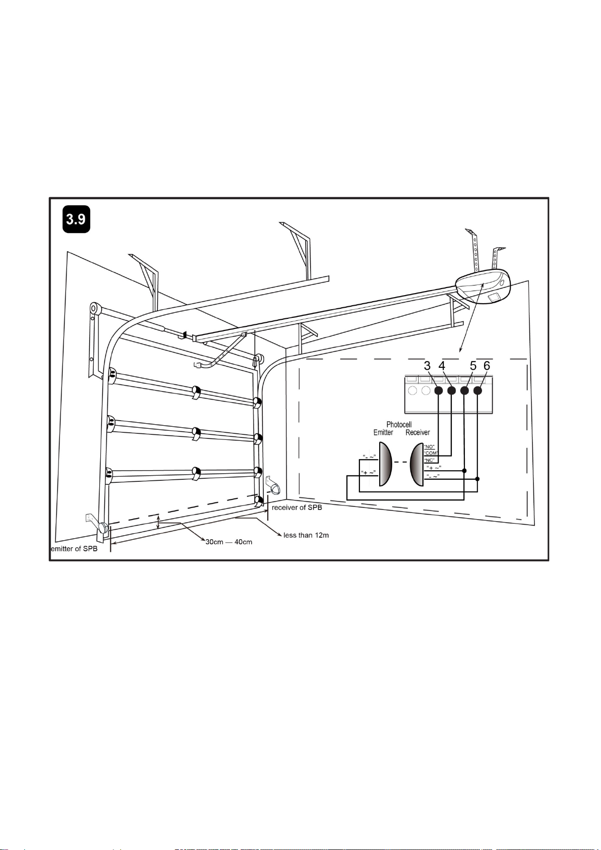
3.9 Install the Safety Photocell Beam (SPB) System (Optional)
1. Position the transmitter and receiver at a height of 30-40cm (11.8”-15.7”) from the ground. For the best
protection, please DON’T exceed the height of 40cm (15.7”).
2.If the TC102 photo eye beam sensor is connected,use a 2-core cable to connect the “+ ~”terminal of the
photocell’s emitter to the terminal 5, the “- ~” terminal to the terminal 6. Also the “+ ~”and “- ~” terminals of
the photocell’s receiver should be connected to the terminals 5 and 6 in parallel.
Use another 2-core cable to connect the “NC”terminal of the receiver to the terminal 3, the “COM”terminal
to the terminal 4.
NOTE: The distance between transmitter and receiver should be less than 12m. Or the SPB will fail in
function and the door opener wouldn’t work normally.
IMPORTANT:
If the photocell is not equipped, you must adjust the “0” in LED to ensure the Photocell set is OFF. Otherwise
the unit can’t work to close at all.
If the photocell is connected, you must adjust the “1”in LED to ensure the photocell set is ON,referring
to step 4.6.
17
4. ADJUSTMENT SECTION
Program Your Opener & Remote
Activate the opener only when door is in full view, free of obstruction and properly adjusted. No
one should enter or leave garage while door is in motion. Do not allow children to operate push
button(s) or remote(s). Do not allow children to play near the door.
Max. 8 remotes can be programmed for the opener. An External Receiver (optional) allows up to
250pcs remotes to be programmed for the opener. TOPENS ERM12 Universal External Receiver
is available at TOPENS Store.
TOPENS ERM12 Universal External Receiver is also compatible with other brand swing gate
opener, sliding gate opener and garage door opener.
Your garage door opener receiver and remote control transmitter are set to a matching code. If you
purchase additional remote controls, the garage door opener must be programmed to accept the new
remote code.
NOTE: Check again for completed and correct assembly of your Opener and Door.
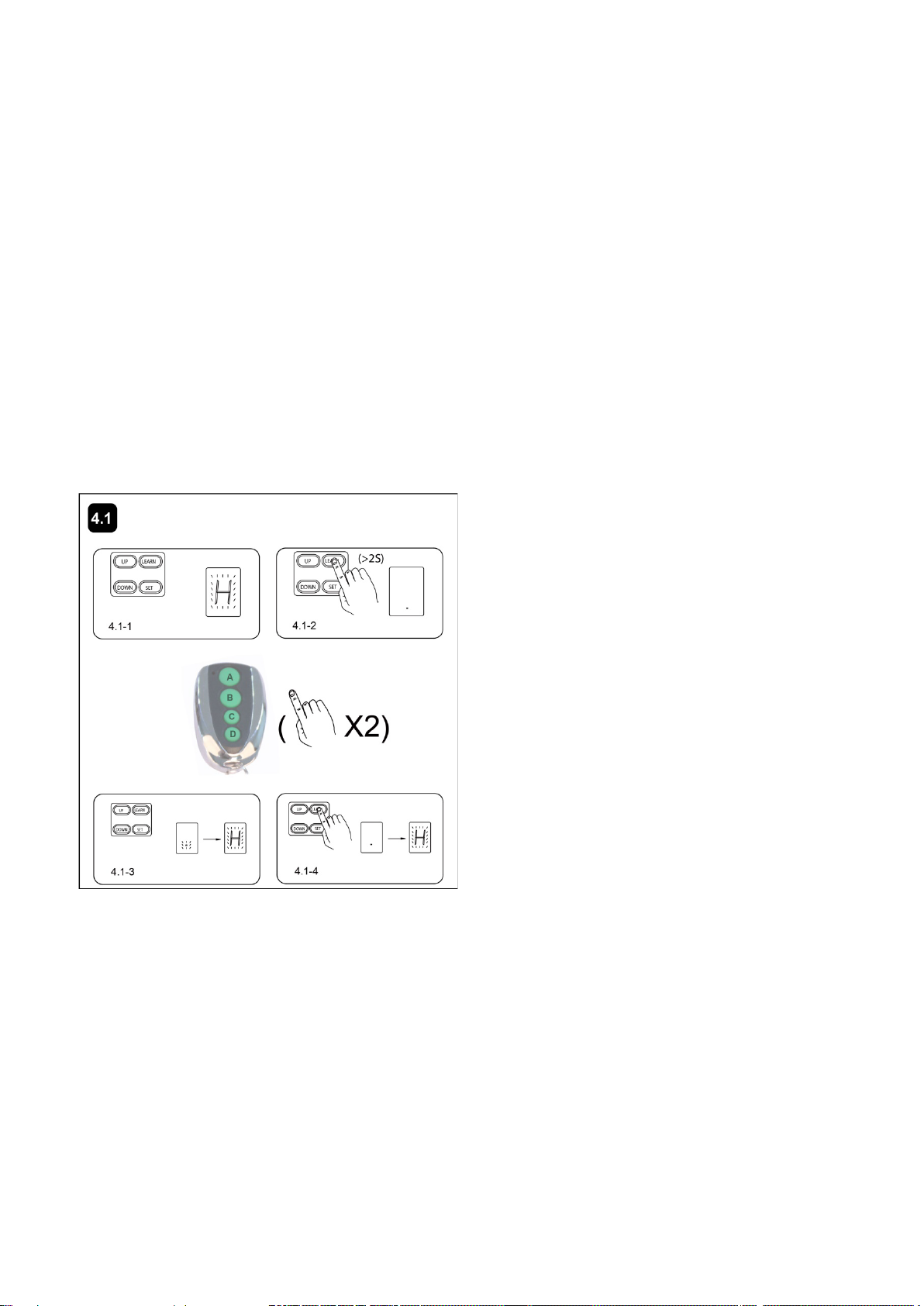
4.1 Learning the code.
To Erase all Remote Control Codes
Press and hold LEARN button on the Opener, the Digital Display indicates “ ·” before it comes to “H”.
The codes are now erased when the Digital Display flashes with “H”(Pic. 4.1-4).
How to use the remote to control the opener
Each of the 4 keys in the remote can be programmed to operate the gate opener. The other 3 keys are
optional for program to operate another garage door opener, swing/sliding gate opener in our brand. But for
sliding gate opener, the Key B is used to achieve the Pedestrian Mode function. When the key has been
programmed, you can press it to operate the corresponding opener to work alternately
(open-stop-close-stop-open).
1. Connect the Cord Plug to power supply. The Digital
Display flashes with “H”, and the Light is ON. The unit
is into standby (Pic.4.1-1).
2.Press and hold LEARN button on the Opener for
more than 2 seconds, the Digital Display indicates “ ·”
(Pic.4.1-2). Press the key (button) two times on the
remote control, between the two times HOLD ON
FOR A MOMENT, and “ ·” flashes several times
before it comes to “H”(Pic. 4.1-3). Now the opener
has learned the code.
NOTE:
If you want the Opener to learn
additional remote codes, perform the above
steps. The Opener can learn 6 remotes at
most.
This manual suits for next models
1
Table of contents
Popular Garage Door Opener manuals by other brands

Nortek
Nortek GoControl GD00Z-4 Installation instructions manual

Chamberlain
Chamberlain 5100-2K owner's manual

Chamberlain
Chamberlain LiftMaster Security+ 2500C owner's manual

Roger Technology
Roger Technology F70/IPU36 Instruction and warnings for the installer

Autoglide
Autoglide CASA-M Series product manual

Zap
Zap Series 3 Technician's installation and service training manual


Erreka
Erreka ARES Quick installation and programming guide

V2
V2 Gold Series manual

Primere
Primere K2R E Installation instruction

GFA
GFA ELEKTROMAT SI 8.20-25,00 10003369 10011 installation instructions

Craftsman
Craftsman 139.18054 owner's manual

moore o matic
moore o matic XX325 Assembly and installation instructions