Patriot Assembly ©2007 MadCow Rocketry™ 3
Step 4 – Fin Assembly
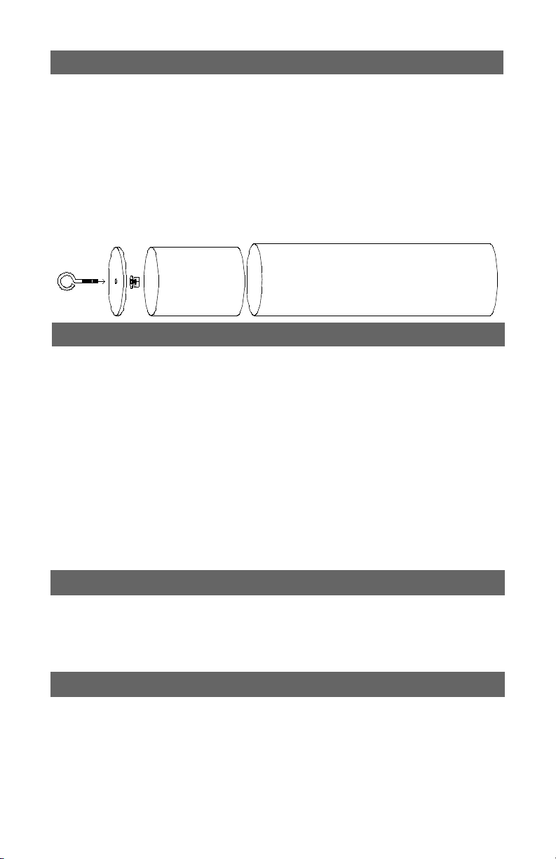
Step 3 – Forward Section Assembly
Using a door jam or small section of angle stock, pencil a line halfway between two of
thensthatextendsfromthefronttothebackofthebodytube.Thislinewillbeused
later to align the rail buttons.
Testteachofthensintotheprecutnslots.Thenshouldseatrmlyagainstthe
motortube-sandeachnifnecessary.Whenyouaresatisedwiththet,applysome
epoxytotheendofthentangthatwillcontactthemotortubeaswellasthenrootthat
willcontactthebodytube.Also,spreadathinlayerofepoxyoneachsideofthentang.
Slidethenintoplaceandcheckthealignment.Continuerecheckingthenalignment
untilyouaresuretheepoxyhasset.Cleananyexcessepoxyfromaroundthenjoint.
Repeatfortheremainingns.
Next,applyepoxylletstobothsidesofeachn.Carefullysmooththeepoxylletswith
yourngerbeforetheepoxysets.Alloweachllettosetbeforerotatingtheairframefor
thenextllet.
Insert the eyebolt through the hole in the center of the bulkhead and secure using the
washer and nut. IMPORTANT: Apply some epoxy to the nut and eyebolt threads
to ensure the nut doesn’t come loose later. Apply some epoxy to the inside of the
coupler and push the bulkhead in so there is about a 1/8” to ¼” of coupler exposed.
Aftertheepoxyhasset,applyalletofepoxyaroundtheinsideedgeofthecoupler
bulkhead joint.
Next mark the coupler 2” from the forward edge. Apply some epoxy to the inside of the
forward body tube section and slide the coupler up to the mark. There should be 4”
of coupler exposed. Make sure the coupler is straight and the body tubes are aligned
properly when they are assembled later.
Step 5 – Rail Button Attachment
Drill a 1/8” hole on the rail button line for the forward and aft rail buttons. The holes
should go into the forward and aft centering rings. Apply a small amount of epoxy in the
holes and attach the rail buttons using the supplied 8-32 screws. Make sure the screw is
loose enough for the rail button to spin freely - this ensures the button is not compressed
to the point it will hang on the rail guide.
Step 6 – Flying Your Model
At this point, pack the chute and assemble the rocket. Insert the largest motor
thatyouintendtoy(orsimulatetheweightwithanappropriatesubstitute)and
ensurethattheCGisforwardofthepointdenedinthespecicationsonthe
rstpage.TheCGshouldbemeasuredfromthetipofthenosecone.Ifthe
CGisbehindthespeciedpoint,addweightinsidethenoseconebypouring
lead shot into the nose cone, adding some epoxy and sealing the hole with a