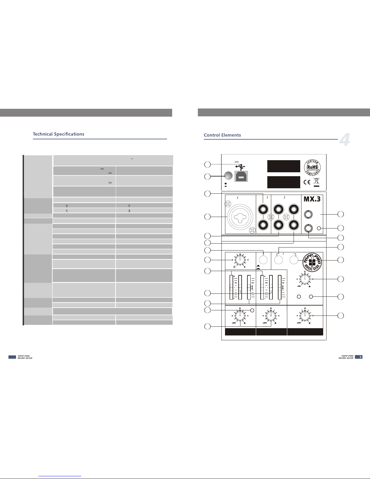
Topp Music Gear MX.3 User manual

10
1010
MON.
MIC LINE 1
IN
HIGH LOW PAN B AL
12KHz 80Hz
CLIP
LINE USB
TO
MAIN
CD TAPE IN
L
R
IN OUT
PEAKLEVEL LEVEL
RL
IN
LINE 2 3 CD TAPE
TO
MONITOR
CH1 CH2/3 MAIN MIX
10
MONITOR
0
L
USB PLAY
LINE IN
HIGH LOW
15
15 R
GAIN
0
L
15
15 R
12KHz 80Hz
L
R
PORTABLE
USB MIXER
50
PWR
MAIN
OUT

MX SERIES MX SERIES

MX SERIES
1. INTRODUCTION.................................................................4
2. FEATURES..........................................................................4
3. INSTRUCTION.....................................................................4
4. CONTROL ELEMENTS.........................................................5
5. CONNECTING DIAGRAMS..................................................7
6. WIRING CONNECTION.......................................................8
7. BLOCK DIAGRAM..............................................................9
8. TECHNICAL SPECIFICATIONS............................................10
9. GUARANTEE.....................................................................12
10. NOTES...........................................................................13
MX SERIES
10

MX SERIES
Thank you for purchasing the TOPP PRO MX.3 compact po rtable
mixer. MX.3 mixer features super mini size but equipped with
powerful functions.
Please carefully read this manual before installation and operation.
Thank you again for choosing TOPP PRO MUSIC GEAR products.
* 1 mic input channels with XLR and balanced line input.
* 1 stereo input channels with RCA jack.
* Ultra-low noise discrete Mic Preamps with +20V Phantom Power.
* 2-band EQ (Warm, natural) in mono and stereo channels.
* 1 Gain control in mono channel.
* Peak LED in mono channel & master.
* 2RCA-Track inputs & 2RCA-Track outputs
* 2RCA-Track inputs assign to Main Mix & Monitor outputs.
* Main Mix & Monitor outputs use 3.5mm stereo jack.
* Built-in stereo USB/Audio interface
* Either USB bus-powered or external adaptor(5VDC 500mA)
MX SERIES
Make sure MX.3 mixer is u sed in the area of ventilation. Do not install
or use this product near any direct hear source(such as amplifier or
heater).
Computer USB power or external voltage converter can also su pply
power to MX.3 mixer.
Note: when using computer USB as power supply, please make sure
the USB port of the computer must comply with the standards of
USB 2.0(5V 500mA)
9
13

MX SERIES
MX SERIES
Main mix Noise
(20 Hz-20 kHz)
Equalization
Main Mix knob/fader @ - ,
Channel Level knob/fader @ - -120dBu(A-weighted)
Main Mix knob/fader @ 0dB,
Channel Level knob/fader @ - -100dBu(A-weighted)
Main Mix knob/fader @ 0dB,
Channel Level knob/fader @ 0dB -98dBu(A-weighted)
Mono channels Stereo channels
Low 15 dB @80 Hz
High 15 dB @12 kHz
MAIN OUT(all knob/fader @ 0 dBu, 22 Hz 22 kHz Filter,
Gain @ unity)
Low 15 dB @80 Hz
High 15 dB @12 kHz
Channel1 +15dBu
PEAK Indicator
Main Left and Right (1-segment)
Clip +15dBu
Line Input
Microphone Input
10k Ohms
2.6k Ohms
Tape Input 10k Ohms
VU Meters
Impedance Main Outputs 120 Ohms
Phones Outputs 120 Ohms
Tape Output 1K Ohms
USB Interface USB 2.0 full speed compliant
USB SECTION
ADC & DAC 16-Bit Delta-Sigma,44.1kHz
Sampling Rates
Operating System
Windows 2000,XP or higher,
Mac OS 9.0.4 or higher, 10.X
or higher
Mic Pin2/Pin3 And Pin1(XLR-3-31
type balanced 1=GND,2=HOT,
3=COLD) +20V
USB Connection DC5V, 500mA
Phantom
power
Power supply Adaptor DC5V, 500mA
Power
Consumption 2.5W
Physical Weight 0.48Kg (1.1 lbs)
Dimension (L*W*H) 98 mm*136 mm*34 mm
8
12
10
1010
MON.
MICL INE 1
IN
HIGH LOW PAN BA L
12KHz 80Hz
CLIP
LINE USB
TO
MAIN
CD TAPE IN
L
R
IN OUT
PEAKLEVEL LEVEL
RL
IN
LINE 23 CDT APE
TO
MONITOR
CH1 CH2/3 MAIN MIX
10
MONITOR
0
L
USB PLAY
LINE IN
HIGH LOW
15
15 R
GAIN
0
L
15
15 R
12KHz 80Hz
L
R
PORTABLE
USB MIXER
50
PWR
MAIN
OUT
1
2
12
4
5
6
7
8
9
10
11
13
18
17
21
19
20
MODEL
SERIAL
ON
OFF
MADE IN CHINA
PWR
DC IN :5VDC 500mA
3
14
15
16

MX SERIES
1- USB PORT
This Type B USB port can be used to connect the computer via Type
B to A connector.
2- POWER SWITCH
To turn on/off the unit.
3- POWER LED
This LED will light up when the unit is powered on.
4- MIC/LINE IN JACK
This combined jack can be used to connect mono signal, such as XLR
microphone or 1/4" line level.
*Note: Please choose balanced cable and MIC to connect. Do not
use th e u nba lanced ones. When the unit is powered on, remember
not to con nect the high level signal to XLR MIC IN, which may dam age
the unit.
5- LINE IN JACK
This RCA jack is used for connecting stereo line in signal source.
6- CD/TAPE IN JACK
This RCA jack is used for connecting stereo line in signal source.
7- CD/TAPE OUT JACK
This RCA jack is used for connecting stereo tape recorder.
8- MAIN OUT JACK
This 3.5mm stereo jack is used to con nect the ac tive stereo speaker.
9- MONITOR OUT JACK
This 3.5mm stereo jack is used to connect the stereo headphone.
10- GAIN CONTROL
It is used for adjust the level of mono input.
11- HIGH
This treble control can be used to reduce the HF noise or boost the
sound of percussion.
MX SERIES
11
12- LOW
This bass control can be used to boost male or effect of drum & bass.
8
Type:
Frequency
Response
Distortion
(THD&N)
MIC EIN
(Equivalent
Input Noise)
CMRR
3 Channel USBMIXER
Mic Input to any Output
(Gain @ 0 dB,Rated output level)
10 Hz to 40 kHz(0, -1dB)
10 Hz to 100 kHz(0, -3dB)
Mic Input to MAIN Output
(Gain @ 0 dB,Rated output
level @ 20 Hz-20 kHz bandwidth) 0.01%(A-weighted)
Input: Channel INPUT MIC
(Rs = 150 , Gain @ Max.,
20 Hz-20 kHz bandwidth) -118dBu(A-weighted)
70dB
Mic in to main out
(Gain @ Max.,@ 1 kHz)
Input Gain
(20 Hz-20 kHz)
Mono Channel
Stereo Channel
MIC:0 to 50dB,LINE:-35 to +15dB
Attenuation
(Crosstalk)
(20 Hz-20 kHz)
Line in, 1/4" TRS Main Out,1 kHz relative to 0 dBu, 22 Hz 22 kHz Filter, Gain @ unity.
Main Mix knob/fader @ - -79dBu(A-weighted)
Channel Level knob/fader @ - -79dBu(A-weighted)
Rated Output
Level
Main, monitor, tape output
(all knob/fader @ 0 dBu,1 kHz)
0dBu
Maximum
Output Level
Main, , tape output
(all knob/fader @ 0 dBu,1 kHz,
22 Hz 22 kHz Filter,THD @ 1%)
monitor
+17dBu
Maximum
Voltage Gain
(EQ and PAN/
BAL knob @
0 dB, Other all
knob or fader
@ max,1 kHz,
Rs=600 )
Mono Channel MIC INPUT
MAIN OUT(3.5 jack stereo)
Mono Channel MIC INPUT
M (3.5 jack stereo)onitor
Mono Channel MIC INPUT
TAPE OUT(RCA)
Mono Channel LINE INPUT
MAIN OUT(3.5 jack stereo)
Stereo Channel LINE INPUT
MAIN OUT(3.5 jack stereo)
TAPE INPUT
MAIN OUT(3.5 jack stereo)
TAPE INPUT
M (3.5 jack stereo)onitor
69dBu
78dBu
69dBu
53dBu
16dBu
6dBu
9dBu

MX SERIES
13- PAN/BAL
This is the panorama control or balanced control. This control is used
for stereo effect field of the signal. Set this control in middle position,
signal levels of Channel L & R will be same. When the control is set to
top stop, only Channel L receives the signal, Channel R can not.
Vice versa.
14- PEAK LED
This is clip LED indicator of mono level. When this LED illumin ates, it
means that PFL mono level is clipped.
15- LEVEL CONTROL
This is channel level control, which is used for adjusting the level of
corresponding channels.
16- LINE IN/USB PLAY
This is path control of the stereo sound source. When this control is
engaged, the signal of channel 2/3 comes from USB PLAY(computer);
when the control is disengaged, the signal will be from RCA j acks of
channel 2/3.
17- CD/TAPE TO MAIN
This is the assignment control of stereo line le vel. When this control
is engaged, the signal of CD/TAPE will be assigned to MAIN MIX OUT.
When the control is disengaged, the assignment will be disconnected.
18- CD/TAPE TO MONITOR
This is the assignment control of stereo line lev el. When t his control
is engaged, the signal of CD/TAPE will be assigned to MONITOR OUT.
When the control is disengage d, MONITOR OUT will receive the sig nal
from MAIN MIX OUT.
19- MONITOR
This is monitor control use d for adjusting the m onito r out put l evel.
20- MAIN MIX
This is main mix control used for adjusting the main mix output level.
MX SERIES
21- CLIP LED(L&R)
This is main mix level clip LED. When this LED lights up, main mix
level will be clipped.
Block Diagram
10

MX SERIES MX SERIES
10
1010
MON.
MICL INE 1
IN
HIGH LOW PAN BA L
12KHz 80Hz
CLIP
LINE USB
TO
MAIN
CD TAPE IN
L
R
IN OUT
PEAKLEVEL LEVEL
RL
IN
LINE 23 CDT APE
TO
MONITOR
CH1 CH2/3 MAIN MIX
10
MONITOR
0
L
USB PLAY
LINE IN
HIGH LOW
15
15 R
GAIN
0
L
15
15 R
12KHz 80Hz
L
R
PORTABLE
USB MIXER
50
PWR
MAIN
OUT
CD PLAYER
COMPUTER
MIC 1
ACTIVE SPEAKERS
DAT OR TAPE
RECORDER
DAT
DAT
HEADPHONE
Mp3 PLAYER
XLR Type Balanced
Pin1 ( )
Pin2 (+)
Pin3 (-)
For XLR Connector
For these applications the unit provides
1/4" TRS and XLR connectors to easily
interface with most professional audio
devices. Follow the configuration
examples below for your particular
connection.
In-line Connection
Tip
Ring
Sleeve
Tip
Ring
Sleeve
Tip
Ring
Sleeve
1
2
3
1
2
3
1
2
3
TIP RING SLEEVE SLEEVE RING TIP
TIP RING SLEEVE
3
Tip
Ring
Sleeve
Tip
Ring
Sleeve
Tip
Sleeve Tip
Sleeve
Tip
Sleeve
Center
Screen
TIP SLEEVE
TIP SLEEVE
TIP RING SLEEVE
SLEEVE TIP
SLEEVE RING TIP
Unbalanced
Balanced
USB Connection
RCA Connection
Tip
Sleeve Center
Screen
TIP RING SLEEVE SLEEVE RING TIP
3.5mm to 3.5mm
Tip
Ring
Sleeve
Tip
Ring
Sleeve
Table of contents
Other Topp Music Gear Mixer manuals