TOPP TF21 Operating and maintenance manual

BEFORE INSTALLING AND USING THE DEVICE, IT IS COMPULSORY FOR
THE INSTALLER AND THE USER TO READ AND UNDERSTAND
THIS MANUAL IN ALL ITS PARTS.
THIS MANUAL IS INTEGRAL PART OF THE DEVICE
AND MUST BE PRESERVED FOR FUTURE
REFERENCE UNTIL DEMOLITION OF THE SAME.
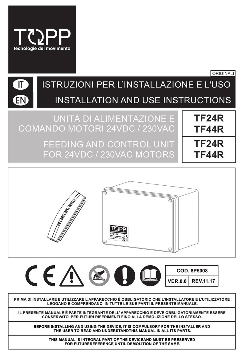
TF21/24R/T
TF41/44R/T
INSTALLATION AND USE INSTRUCTIONS
FEEDING AND CONTROL UNIT
FOR 24VDC / 230VAC MOTORS
P/N 8P5021
VER.1.0 REV.07.04


3
INDEXTF21/44R/T
INSTALLATION AND USE INSTRUCTIONS
1- DECLARATION OF "CE" CONFORMITY ....................................page 04
2- GENERAL REMARKS
2.1- General instructions ..........................................................................page 05
2.2- Installer and user...............................................................................page 05
2.3- Warranty............................................................................................page 05
2.4- Technical assistance..........................................................................page 05
2.5- Reserved rights (Copyright) ..............................................................page 05
3- TECHNICAL DESCRIPTION
3.1- Rating plate and "CE" marking..........................................................page 06
3.2- Denomination of the components and dimensions ...........................page 07
3.3- Technical data ...................................................................................page 08
3.4- Destination of use .............................................................................page 08
3.5- Use Limits .........................................................................................page 09
3.6- Package ............................................................................................page 09
4- SAFETY
4.1- Protections against electric hazard ...................................................page 10
4.2- Residual risks....................................................................................page 10
5- INSTALLATION
5.1- General instructions ..........................................................................page 11
5.2- Installation of the sensors..................................................................page 11
5.3- Installation of the power supply unit ..................................................page 12
5.4- Tripping of the sensors......................................................................page 13
5.5- Technical information on operation ...................................................page 13
5.6- Automatic operation with predefined logic.........................................page 13
5.7- Programming of remote electronic control mod. F33 ........................page 16
5.7.1- Programming reset.........................................................................page 17
5.8- Electric connections ..........................................................................page 18
6- USE AND OPERATION
6.1- Use of the device...............................................................................page 23
7- DEMOLITION
7.1- General instructions ..........................................................................page 24
8- SPARE PARTS AND ACCESSORIES UPON REQUEST
8.1- General instructions ..........................................................................page 24
8.2- Accessories upon request .................................................................page 24
VER.1.0
REV.07.04

TOPP SPA - Via Galvani, 59
36066 SANDRIGO (VI) - ITALIA
Tel. +39 0444656700
Fax +39 0444 656701
Declares that the electric device
called: FEEDING AND CONTROL UNIT FOR 24VDC/230VAC MOTORS
Type: TF Models: TF21 - TF21R/T - TF24 - TF24R/T 24VDC
TF41 - TF41R/T - TF44 - TF44R/T 230VAC
Serial No.: see rating plate and CE marking applied on the device
Year of construction: 2004
complies with the requirements of the following directives:
73/23/EEC
(Low Voltage Directive: electrical equipment destined to be used within given voltage limits)
89/336/EEC
(Electromagnetic Compatibility Directive - on the approximation of the laws of the
Member States relating to electromagnetic compatibility)
and, besides, it declares that the following harmonized standards have been
applied:
EN 60950:1992- 08; EN 60950 EC:1992-10; EN 60950/A1:1993;
EN60950/A2:1993- 08; EN 60950/A3:1995- 10; EN 60950/A3 EC:1996- 01;
EN 60950/A4:1997- 03; EN 60950/A11:1997- 10; EN55022:1998;
EN61000- 3- 2:1995; EN61000- 3- 3:1995; EN61000- 3- 2/A1:1998;
EN61000- 3- 2/A2:1998; EN50130- 4:1995; EN50130- 4/A1:1998
Date: 07/01/2004
Surname and name: Matteo Cavalcante
Signature...........................................................
4
TF21/44R/T
INSTALLATION AND USE INSTRUCTIONS
1- DECLARATION OF "CE" CONFORMITY
VER.1.0
REV.07.04

2.1- GENERAL INSTRUCTIONS
BEFORE INSTALLING AND USING THE DEVICE, IT IS COMPULSORY THAT THE
INSTALLER AND THE USER CAREFULLY READ AND UNDERSTAND THIS MANUAL IN
ALL ITS PARTS.
THIS MANUAL IS INTEGRAL PART OF THE DEVICE AND MUST COMPULSORILY BE
PRESERVED FOR FUTURE REFERENCE.
THE MANUFACTURER HAS NO LIABILITY FOR ANY EVENTUALDAMAGE TO PERSONS,
ANIMALS AND THINGS DUE TO THE INOBSERVANCE OF THE STANDARDS DESCRIBED
IN THIS MANUAL.
2.2- INSTALLER AND USER
THE DEVICE INSTALLATION CAN BE PERFORMED EXCLUSIVELY BYCOMPETENT AND
QUALIFIED TECHNICAL PERSONNEL SATISFYING THE PROFESSIONAL AND
TECHNICAL REQUIREMENTS FORESEEN BY THE LAWS IN FORCE IN THE COUNTRYOF
INSTALLATION.
THIS DEVICE CAN BE USED EXCLUSIVELY BY A USER ACTING IN CONFORMITY WITH
THE INSTRUCTIONS CONTAINED IN THIS MANUAL.
2.3- WARRANTY
THE DEVICE WARRANTY EXPIRES, IF ITS USE DOES NOT COMPLY WITH THE
INSTRUCTIONS AND PRESCRIPTIONS DESCRIBED IN THIS MANUAL, AS WELL AS IF
NON-ORIGINAL COMPONENTS, ACCESSORIES, SPARE PARTS, AND CONTROL
SYSTEMS ARE USED (SEE LAST PAGE).
2.4- TECHNICAL ASSISTANCE
For the technical assistance apply to your Dealer or to the Manufacturer.
2.5- RESERVED RIGHTS
The reserved rights on this manual "Installation and use instructions" remain property of
the Manufacturer.
Each information herein contained (text, drawings, diagrams, etc.) is reserved.
None part of this manual can be reproduced and disclosed (totally or partially) by any
reproduction means (photocopies, microfilms or other) without written authorization of
the Manufacturer.
5
TF21/44R/T
INSTALLATION AND USE INSTRUCTIONS
GENERAL REMARKS -2
VER.1.0
REV.07.04

3.1- RATING PLATE AND "CE" MARKING
The CE marking certifies the compliance of the machine with the essential safety and
health requirements foreseen by the product European Directives.
The rating plate is an adhesive plate in polyester, silk-screen printed in black, having the
following size: L=36 mm - H=50 mm.
It is applied externally on the device. The plate (Fig.1) bears in readable and indelible
way the following data:
• logo and address of the manufacturer
• type and model
•
• output voltage (A)
• absorbed electric power P (W)
• symbol of double insulation
• CE marking
• serial number
• year of construction
Power supply voltage and frequency (V-Hz)
6
TF21/44R/T
INSTALLATION AND USE INSTRUCTIONS
3- TECHNICAL DESCRIPTION
VER.1.0
REV.07.04

7
3.2- DENOMINATION OF THE COMPONENTSAND DIMENSIONS
Fig.2 Dimensions in mm
TF21/44R/T
160
120
75
INSTALLATION AND USE INSTRUCTIONS
TECHNICAL DESCRIPTION -3
230V - 50Hz MAINS WIND
SENSOR
RPR RAIN
SENSOR
SUN
SENSOR
CONTROLS OF ALL
MOTORS CONNECTED
FEEDING AND
CONTROL UNIT
CONTROLS OF
SINGLE OUTPUTS
24Vdc/230Vac MOTORS
(see Table 1)
INFRARED RAY
REMOTE CONTROL
433 Mhz RADIO
CONTROL
VER.1.0
REV.07.04

3.3- TECHNICAL DATA
Tab.1 contains the technical data characterising the device.
8
Tab.1
230 V - 50 Hz
230 Vac
TF21/RT TF24/RT TF41/RT TF44/RT
0,36 A 1,5 A
15 W 45 W
Yes
- 5 ºC + 50 ºC
160 x 120 x 75 mm
1,3 kg
24 Vdc
1,3 A 5,2 A
300 W 1200 W
TF21/44R/T
3.4- DESTINATION OF USE
THE DEVICE HAS BEEN DESIGNED AND MANUFACTURED ONLY TO FEED AND
CONTROL "ORIGINAL TOPP" MOTORS: WINDOW AUTOMATION ACTUATORS - MOD.
C20 - ACK4 - SL60 - C30 - C40.
INSTALLATION AND USE INSTRUCTIONS
3- TECHNICAL DESCRIPTION
Power supply voltage
Output voltageVdc - Vac
Max. output current
Absorbed power
Service
Prearrangement connection
to external devices
Double electric insulationyes
Operating temperature
Dimensions
Connectable C20 actuators
Connectable ACK4 actuators
Connectable SL60 actuators
Connectable C30 actuators
Connectable C40 actuators
Gross weight
Wind, rain, brightness sensors
and manual control
According to the motors connected
VER.1.0
REV.07.04
N.2
N.4
N.4
N.8
N.16
N.16
N.4
N.1
N.1
N.1
/ /
/
/ N.4 N.16
N.5 N.20N.1/

9
TF21/44R/T
3.5- USE LIMITS
3.6- PACKAGE
The device has been designed and manufactured exclusively for the destination of use
given in par.3.4, therefore, any other type of use is strictly forbidden in order to assure
in any moment the safety of the installer and of the user, as well as the efficiency of the
device itself.
IT IS STRICTLY FORBIDDEN TO USE THE DEVICE FOR IMPROPER USES, DIFFERING
FROM THE ONE FORESEEN BY THE MANUFACTURER (SEE PAR.3.4).
IT IS STRICTLY FORBIDDEN TO INSTALL THE DEVICE ON THE EXTERNAL SIDE OF THE
ROOM SUBJECT TO ATMOSPHERIC AGENTS (RAIN, SNOW, ETC.).
THE USE OF THE DEVICE IN ENVIRONMENTS WITH POTENTIALLY EXPLOSIVE
ATMOSPHERE IS STRICTLY FORBIDDEN.
IT IS COMPULSORY TO KEEP THE PACKAGE AND THE DEVICE OUT OF REACH OF
CHILDREN.
Each standard package of the product (cardboard box) contains:
• No. 1 Feeding and control unit for 24VDC/230VAC motors;
• No. 3 Fairleads (ø 6) for connection cables;
• No. 1 Package with dowels and fastening screws;
• No. 1 433 MHZ Radio control (only for mod. TF21R, TF24R, TF41R and TF44R);
• No. 1 Infrared remote control (only for mod. TF21T, TF24T, TF41T and TF44T);
• No. 1 Installation and use instructions.
MAKE SURE THAT THE ABOVE DESCRIBED COMPONENTS ARE CONTAINED IN THE
PACKAGE, AS WELL AS THAT THE DEVICE HAS NOT BEEN DAMAGED DURING
TRANSPORT.
SHOULD ANY ANOMALY BE DETECTED, IT IS FORBIDDEN TO INSTALL THE DEVICE,
AND IT IS COMPULSORY TO REQUIRE TECHNICALASSISTANCE FROM YOUR DEALER
OR THE MANUFACTURER.
THE PACKAGING (PAPER, PLASTIC, ETC.) HAS TO BE DISPOSED ACCORDING TO THE
LAWS IN FORCE.
EX
INSTALLATION AND USE INSTRUCTIONS
TECHNICAL DESCRIPTION -3
VER.1.0
REV.07.04

4.1-
4.2-
PROTECTIONS AGAINST ELECTRIC HAZARD
The device is protected against electric hazard due to direct and indirect contacts.
The protection measures against direct contacts aim at protecting people against
hazards due to contact with active parts, usually live parts; while the protection
measures against indirect contacts aim at protecting people against hazards due to
conducing part, which are usually insulated, but could become live in case of failure
(insulation failure).
The adopted protection measures are the following:
1) Insulation of live parts by means of a plastic material body;
2) Enclosure with suitable protection degree;
3) Protection of passive type given by the use of components with double insulation,
also called components of class II or with equivalent insulation (it is forbidden to
perform the connection to the earthing plant of the devices equipped with double
insulation).
RESIDUAL RISKS
The device does not have residual risks. The installer and the user are herewith
informed that after the actuators have been installed on the window, the automatic
enabling of the same can accidentally generate the following residual risk:
Residual risk:
Hazard of squashing or dragging of body parts inserted between the movable and the
fix part of the window frame.
Exposure frequency:
Accidental and when the installer or the user decides to perform a wrong voluntary
action.
Severity of the damage:
Light lesions (usually reversible).
Adopted measures:
1) Manual control (remote control, radio control or push-button): It is compulsory to
verify that near the window there are not persons, animals or things whose safety
may be accidentally jeopardized. During actuator operation, it is compulsory to be in
a safe control position assuring visual control on the window movement.
2) Automatic control (sensors): It is compulsory to place on the window suitable safety
signals and/or to install a suitable acoustic/light signaller nearby.
10
TF21/44R/T
INSTALLATION AND USE INSTRUCTIONS
4- SAFETY
VER.1.0
REV.07.04

11
INSTALLATION -5
5.1-
5.2-
GENERAL INSTRUCTIONS
THE DEVICE INSTALLATION CAN BE PERFORMED EXCLUSIVELY BYCOMPETENT AND
QUALIFIED TECHNICAL PERSONNEL SATISFYING THE PROFESSIONAL AND
TECHNICAL REQUIREMENTS FORESEEN BY THE LAWS IN FORCE IN THE COUNTRYOF
INSTALLATION.
BEFORE CONNECTING THE MOTORS (ACTUATORS) TO THE FEEDING AND CONTROL
UNIT, VERIFY THAT THEY ARE CORRECTLY INSTALLED ON THE FRAMES IN
COMPLIANCE WITH THE RELATED "INSTALLATION AND USE INSTRUCTIONS".
THE DEVICE HAS TO BE PLACED WITHIN THE ROOM IN A SUITABLE POSITION
ACCORDING TO THE DISTANCE OF THE MOTORS (ACTUATORS) TO BE CONTROLLED
IN COMPLIANCE WITH THE SAFETY CONDITIONS FORESEEN BY THE LAWS IN FORCE
IN THE COUNTRY OF USE.
THE FOLLOWING INSTRUCTIONS, TO EASE UNDERSTANDING, REFER TO A FEEDING
AND CONTROL UNIT CALLED TF2 FOR FOUR MOTORS, SINCE THE ONE FOR ONE
SINGLE MOTOR HAS A SIMILAR OPERATION.
INSTALLATION OF THE SENSORS
THE INSTALLATION OF THE SENSORS FOR WIND, RAIN, SNOW, ETC. HAS TO BE
PERFORMED OUTSIDE THE BUILDING, PREFERABLY ON THE ROOF OR IN A SIMILAR
POSITION.
1) The rain sensor has to be placed with an inclination of 5°÷10° with reference to the
horizon and in such a position as not to have shields against rain fall (the positioning
under trees or close to walls shall be avoided since this alters the natural
meteorological event);
2) The wind sensor shall be located far from hindrances, which influence the wind flow
(gutters, trees, walls, etc.);
3) The brightness sensor (sun) has to be placed in such a position as to assure the
same intensity of light perceived on the windows on which are installed the motors
(actuators) fed and controlled by the feeding unit.
TF21/44R/T
INSTALLATION AND USE INSTRUCTIONS
VER.1.0
REV.07.04

12
5- INSTALLATION TF21/44R/T
5.3- INSTALLATION OF THE POWER SUPPLYUNIT
BEFORE INSTALLING THE FEEDING UNIT PERFORM THE CORRECT INSTALLATION OF
THE SENSORS (SEE PAR.5.2) AND THE WIRING OF THE CONNECTION WIRES OF THE
SAME.
1) Open the package (par.3.6)and extract the various components;
2) Select the input position on the feeding unit of the sensor wires and mark the related
drilling points;
3) Open the cover of the feeding unit container;
IN THE COVER OF THE VERSION TF24 IT IS INSTALLED THE ELECTRONIC CARD THAT IS
CONNECTED BY THREE WIRES TO THE POWER TRANSFORMER. PAY UTMOST CARE
NOT TO DAMAGE THE ELECTRIC CONNECTIONS OR THE CONNECTION TO THE
TERMINALS.
4) Using a suitable drill, perform holes having a diameter of 3.5 mm on the two
impressions prearranged for the fastening screws located on the bottom of the
container;
It is suggested to select them diagonally to each other avoiding the ones close to the
transformer;
5) With a suitable drill, perform in the container holes having a diameter of 10 mm in the
inlet points of the sensor wires marked at step 2);
6) In the holes having a 10 mm diameter mount the fairleads included in the standard
supply;
7) Place the container in the pre-selected position and through the holes having 3.5 mm
diameter mark with a pencil the drilling points on the installation support (wall or
other) of the feeding unit. Check the perfect horizontal and vertical alignment;
8) With a suitable drill, perform holes having a diameter corresponding to the dowels
and to the screws included in the standard supply;
9) Mount the container of the feeding unit and tighten the screws definitively;
10) Prearrange the wires of the sensors and of the motors to be connected placing them
suitably in order to perform a correct ordered and functional electric connection;
11) Perform the electric connections in compliance with the provisions of par. 5.8 and
with reference to the wiring diagram corresponding to the purchased feeding unit
model;
12) Perform the final test, verifying the correct tripping of the sensors according to the
prescriptions of the following paragraph.
INSTALLATION AND USE INSTRUCTIONS VER.1.0
REV.07.04

5.4-
TRIPPING OF THE SENSORS
• In order to let the rain sensor trip, it is sufficient to touch with a finger for some second
the sensitive part (there is not hazard of electric shock since the device is protected
and works at low voltage).
• In order to let the wind sensor trip, let the fan rotate for at least 5 seconds.
• In order to let the brightness (sun) sensor trip, it is sufficient to cover it with a cloth
and then to uncover it. The cloth shall preferably have a dark colour. Perform the
tripping adjustment according to the prescriptions of the following paragraph.
5.5- TECHNICAL INFORMATION ON OPERATION
The control unit TF2 can operate the connected motors (actuators) manually or
automatically by means of the sensors connected to it.
For the manual operation, it is necessary to connect temporarily the feeding unit to a
manual push-button (also called "with man present") of approved bipolar type, or in the
mod. …R or in the mod. …T, the control occurs by means of 433MHz radio control or by
infrared remote control.
5.6- AUTOMATIC OPERATION WITH PREDEFINED LOGIC
The automatic operation follows a predefined logic.
1) When an atmospheric event of rain or wind beyond the pre-set limits occurs, the
feeding unit closes automatically the connected windows independently from the
control status. In other words, the automatic command takes priority on any other
command given.
2) The automatic closing command due to wind or rain is enabled for 1 minute.
After the closing command due to wind, all manual commands are inhibited for 6
minutes.
3) The forced manual re-opening is allowed also with enabled rain sensor.
After 10 minutes from the opening command, if the sensor is still wet, the windows
close; while if it is dry, they remain open.
4) The value referred to the wind speed can be calibrated by acting on the DIP-Switch
housed on the electronic card. The feeding unit starts to work when the wind speed
exceeds the value set in the programmed “DIP-Switch”;
The programming codes are given in Tab.2:
13
TF21/44R/T
INSTALLATION AND USE INSTRUCTIONS
INSTALLATION -5
VER.1.0
REV.07.04

5) The sun or brightness sensor (available only for TF24, TF24/R, TF24/T and TF44,
TF44/R and TF44/T) enables by means of the “DIP-switch” No.6 that has to be in
OFF position;
6) The brightness (sun) sensor trips any time that the light intensity value exceeds the
programmed threshold and remains at those values for at least 10 consecutive
minutes. The tripping threshold is adjusted by acting on the Trimmer RT1 (Fig.3)
placed on the electronic card of the control unit. The trimmer adjusts from
0(darkness) to about 50 klx (shining sun and clear midday sky) with intermediate
progressive values; (see diagram given here below). The exceeding of the threshold
set on the trimmer generates an OPEN/CLOSE command to the motors connected
to the outputs M5 and M6 (motors No.3 and No.4);
Tab.2
Tab.3
Speed
5 km/h - (2,083 Hz)
10 km/h - (4,167 Hz)
15 km/h - (6,250 Hz)
20 km/h - (8,333 Hz)
25 km/h - (10,417 Hz)
30 km/h - (12,500 Hz)
35 km/h - (14,583 Hz)
40 km/h - (16,667 Hz)
DIP-switch
N.1 N.2 N.3
OFF OFFOFF
OFF OFFON
ON OFFOFF
ON OFFON
OFF ONOFF
OFF ONON
ON ONOFF
ON ONON
OFF
ON
14
TF21/44R/T
Fig.3
INSTALLATION AND USE INSTRUCTIONS
5- INSTALLATION
Function DIP-Sw. No.6
Brightness sensor enabled (wind/rain sensors outputs M5-M6 disabled)
Brightness sensor disabled (wind/rain sensors outputs M5-M6 enabled)
klx
VER.1.0
REV.07.04

7) The brightness (sun) sensor requires to disable the controls of the rain and wind
sensors for the outputs M5 and M6 by means of the “DIP-switch” No.6, which has to
be on “OFF” position. The brightness sensor can have two opposite functions;
To select the wished function, it is necessary to act on the “DIP- switch”No.4 placed
on the electronic card programming it as follows:
8) By programming the “DIP-switch” No.5, it is possible to modify the type of control.
When the “DIP-switch” is programmed on "AUTOMATIC" mode, the control by
manual push-button, radio control or remote control operates on a step by step
system basis (open, stop, close, stop, etc.). When it is programmed on "MAN
PRESENT" mode, only the manual push-button is enabled. This choice of indirect
safety excludes consequently all commands coming from radio control and remote
control.
To vary this function, set the following programming:
15
TF21/44R/T
Tab.4
Tab.5
ON
OFF
OFF
ON
INSTALLATION AND USE INSTRUCTIONS
INSTALLATION -5
Function Position of DIP-switch No.6
If the OPEN (+ light) threshold is exceeded
If the CLOSE (+ light) threshold is exceeded
Function Position of DIP-switch No.5
Automatic
Man present
VER.1.0
REV.07.04

5.7- PROGRAMMING OF REMOTE ELECTRONIC CONTROL MOD. F33.
THIS CHAPTER DESCRIBES THE PROGRAMMING OF THE "433 MHz RADIO CONTROL"
MOD. F33.
The green LED DL1 blinks every time the receiver within the feeding unit receives a
valid code from the radio control, even if it has not been programmed. In this way, it is
possible to have more information on the possible malfunctions of the system.
Given that the used coding is with variable code, each remote control sends a signal
that is different from all the others. Therefore, the receiver must be able to recognise
the enabled remote controls.
To each push-button corresponds an Moutput:
To output M3 corresponds the push-button on the top left side
To output M4 corresponds the push-button on the top right side
To output M5 corresponds the push-button on the bottom left side
To output M6 corresponds the push-button on the bottom right side
16
TF21/44R/T
INSTALLATION AND USE INSTRUCTIONS
5- INSTALLATION
VER.1.0
REV.07.04

To enable a remote control proceed as follows:
• Press SP2 until the RED LED DL2 lights.
Then release it.
• Press any key of the remote control that you wish to enable.
When the receiver receives the signal from the remote control, the LED DL2 switches
off.
• Press again, a second time, the key of the remote control.
The LED DL2 blinks for a while to indicate that the remote control has been
programmed.
• Repeat the steps described above for each remote control that you wish to enable.
THE PROGRAMMING PHASE ENDS, IF THE RECEIVER DOES NOT RECEIVE ANY VALID
CODE WITHIN 30 SECONDS.
THE RECEIVER CAN STORE UP TO 6 REMOTE CONTROLS. AN EVENTUAL SEVENTH
REMOTE CONTROL WILL NOT BE ACCEPTED.
DURING THE PROGRAMMING PHASE, MOVE THE REMOTE CONTROL AWAY FROM THE
RECEIVER OF AT LEAST 1.5 METERS.
5.7.1- PROGRAMMING RESET
Should you wish to delete all programmed remote controls, press the key SP2 on the
electronic card of the control unit until the LED DL2, which has in the meanwhile
switched on, does not start to blink. At this point, all remote controls previously stored in
the receivers have been deleted. The deletion lasts about 8 seconds.
17
TF21/44R/T
INSTALLATION AND USE INSTRUCTIONS
INSTALLATION -5
VER.1.0
REV.07.04

5.8- ELECTRICAL CONNECTIONS
BEFORE PERFORMING THE ELECTRIC CONNECTION OF THE FEEDING UNIT, VERIFY
THE CORRECT INSTALLATION OF THE MOTORS (ACTUATORS).
THE MAINS TO WHICH THE FEEDING UNIT IS CONNECTED MUST COMPLY WITH THE
REQUIREMENTS OF THE LAWS IN FORCE IN THE COUNTRY OF INSTALLATION, AS
WELL AS SATISFY THE TECHNICAL FEATURES GIVEN IN TAB.1 AND ON THE RATING
PLATE AND THE "CE" MARKING (PAR.3.1), AS WELL AS BE EQUIPPED WITH A
SUITABLE "EARTHING PLANT".
THE SECTION OF THE MAINS CABLES MUST BE PROPERLY SIZEDACCORDING TO THE
ABSORBED ELECTRIC POWER (SEE RATING PLATE AND "CE" MARKING).
ANY TYPE OF ELECTRIC MATERIAL (PLUG, CABLE, TERMINALS, ETC.) USED FOR THE
CONNECTION MUST BE SUITABLE FOR THE USE, WITH "CE" MARKING, AND
COMPLYING WITH THE REQUIREMENTS FORESEEN BY THE LAWS IN FORCE IN THE
COUNTRY OF INSTALLATION.
IT IS COMPULSORY TO INSTALL UPSTREAM OF THE MAINS A SECTIONING DEVICE
WITH A 30 mA DIFFERENTIALPROTECTION, ASSOCIATED TO THE EARTHING PLANT.
IT IS FORBIDDEN TO PERFORM THE CONNECTION OF THE FEEDING AND CONTROL
UNIT TO THE EARTHING PLANT.
THE FEEDING AND CONTROL UNITS MOD. TF21 AND TF24 CAN BE SUPPLIEDALSO BY
A 24V DC EXTERNAL SOURCE BY MEANS OF THE "ORIGINAL TOPP" FEEDER MOD.
AL/TF WITH BUFFER BATTERIES. IN THIS CASE, THE CONNECTION HAS TO BE
PERFORMED ON THE SUITABLE TERMINAL BOARD (M2) OF THE ELECTRONIC CARD
OF THE FEEDING AND CONTROL UNIT.
THE ELECTRIC CONNECTION OF THE ACTUATOR CAN BE PERFORMED ONLY BY
COMPETENT AND QUALIFIED TECHNICAL PERSONNEL SATISFYING THE TECHNICAL
AND PROFESSIONAL REQUIREMENTS FORESEEN BY THE LAW IN FORCE IN THE
COUNTRY OF INSTALLATION ISSUING TO THE CUSTOMER A DECLARATION OF
CONFORMITY FOR THE CONNECTION AND/OR THE PLANT PERFORMED.
18
TF21/44R/T
INSTALLATION AND USE INSTRUCTIONS
5- INSTALLATION
VER.1.0
REV.07.04
665544332211
19
TF21/44R/T
230V ~ 50Hz
M
MM
BLUE
0
12
24
M3 M2 M1
F1
A
C
BLUE
BLUE
DP1
UO1
RT1
T
SP2
U4 SW1
M11 SP1 DL1
JP2 JP3
DL2
IT IS FORBIDDEN TO PERFORM THE CONNECTION TO THE
EARTHING PLANT OF THE DEVICES EQUIPPED WITH DOUBLE
INSULATION.
INSTALLATION AND USE INSTRUCTIONS
INSTALLATION -5
Wiring diagram Mod. TF21
Connection to the feeder
with buffer batteries AL TF
BROWN
BROWN
YELLOW
WHITE
Remote control
programming
push-button
Manual control
(A=OPEN - C=CLOSE)
VER.1.0
REV.07.04
112233445566
20
TF21/44R/T
230V/24V
0
10V~
24V~
M6 M5 M4 M3 M2 M1
230V ~ 50Hz
2
1
MM
0
12
24
3
4
BLUE
BLUE
BLUE
F1
JP3
JP2
RT1
DP1
UO1
U4 SW1
SP2
SP1
DL2 DL1
M7
M8 M12 M9 M10 M11
AAAAA
CCCCC
N.4 N.3 N.2 N.1
IT IS FORBIDDEN TO PERFORM THE CONNECTION TO THE
EARTHING PLANT OF THE DEVICES EQUIPPED WITH DOUBLE
INSULATION.
INSTALLATION AND USE INSTRUCTIONS
5- INSTALLATION
BROWN
BROWN
BROWN
LIGHT BLUE
BROWN
BROWN
LIGHT BLUE
BROWN
LIGHT BLUE
BROWN
LIGHT BLUE
WHITE
WHITE
GREY
RED
RED
YELLOW
Transformer
Motors No.1 and 2
window
opening/closing
Motors No.3 and 4 window
opening/closing
or, alternatively, internal
curtain or roller
shutter motors
External feeder
module terminal
board with buffer
batteries AL TF
Heated rain
sensor
Wind sensor
Brightness (sun)
sensor
(A=OPEN C=CLOSE)
Single manual controls
General
control
Motor f. Motor f.Motor f.
Roller
shutter
curtain
Motor f.
Roller
shutter
curtain
Remote control
programming
push-button
Wiring diagram Mod. TF24
VER.1.0
REV.07.04
This manual suits for next models
11
Table of contents
Other TOPP Control Unit manuals
Popular Control Unit manuals by other brands

Rockwell Automation
Rockwell Automation Allen-Bradley 2198-R031 installation instructions

WNC
WNC M14Q2FG user manual

Pololu
Pololu Romi 32U4 Schematic diagram

GORMAN-RUPP
GORMAN-RUPP GRP33-08A Installation, operation, and maintenance manual with parts list

Microhard Systems
Microhard Systems Nano Series operating manual

Mantracourt
Mantracourt T24-SAf user manual