RAKwireless WisDuo-LoRa Series User manual

2
Table of Contents
1. Overview................................................................................................................................................ 3
1.1 Introduction................................................................................................................................. 3
1.2 Main Features ............................................................................................................................. 3
2. RAK4200(H) LoRa Module........................................................................................................... 4
2.1 Overview....................................................................................................................................... 4
2.2 Pin Definition & Pin Out.......................................................................................................... 4
2.3 Mechanical Dimensions........................................................................................................... 6
2.4 Recommended Footprint........................................................................................................ 7
2.5 Recommended Reflow Profile............................................................................................... 7
3. Warning.................................................................................................................................................. 9
4. Revision History.............................................................................................................................. 10
5. Document Summary.....................................................................................................................10

3
1. Overview
1.1 Introduction
RAK4200(H) LoRa Module includes an STM32L071 MCU and an SX1276 LoRa chip. It
has Ultra-Low Power Consumption of 1.5uA in sleep mode and high LoRa output power
up to 13.92dBm max in work mode.
The module complies with LoRaWAN 1.0.2 protocols. It also supports Lora Point to Point
communications. The module is suitable for various applications that require long range
data acquisition and low power consumption.
1.2 Main Features
LoRa module for Smart City, Smart Agriculture, Smart Industry
Compact Form Factor: 15 x 15.5 x 2.5 mm
20 Pin Stamp Pad for PCB SMT mounting
I/O ports: UART/I2C/GPIO
Temperature range: -40°C to +85°C
Supply voltage: 2.0 ~ 3.6V
Frequency range: 902.3-914.9 MHz, 903~927.5 MHz
IEEE 802.15.4g, Wireless M-Bus and Proprietary Systems
Low-Power Wireless Systems
Ultra-Low Power Consumption 1.5uA in sleep mode
Core: ARM 32-bit Cortex –M0+ with MPU
Up to 192KB flash memory with ECC
20KB RAM
6KB of data EEPROM with ECC

4
2. RAK4200(H) LoRa Module
2.1 Overview
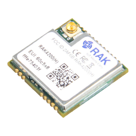
The figure below shows the top view of the RAK4200(H) LoRa Module. The dimensions of
the Module are 15 x 15.5 x 2.5 mm.
Figure 1 | RAK4200(H) LoRa Module
2.2 Pin Definition & Pin Out
The figure below shows the pinout of the RAK4200(H) LoRa Module.

5
Figure 2 | Pinout
The table below shows the pin definition of the RAK4200(H) LoRa Module.
Pin
Name
I/O
Description
1
UART2_RX
I
Main UART (STM32L071K8 PA10)
2
UART2_TX
O
Main UART (STM32L071K8 PA9)
3
UART2_DE
I/O
GPIO (STM32L071K8 PA12)
4
UART1_TX
I/O
General GPIO or UART(Reserved)
(STM32L051K8 PA2)
5
UART1_RX
I/O
General GPIO or UART(Reserved)
(STM32L051K8 PA3)
6
UART1_DE
I/O
General GPIO or UART(Reserved)
(STM32L051K8 PA1)
7
SWDIO
I/O
Programming (STM32L051K8 PA13)
8
SWCLK
I/O
Programming (STM32L051K8 PA14)
9
I2C_SCL
I/O
I2C interface (STM32L051K8 PB6)
10
I2C_SDA
I/O
I2C interface (STM32L051K8 PB7)
11
GND
-
Ground
12
RF
I/O
RF port (reserved), default RF out by IPEX
13
GND
-
Ground
14
GND
-
Ground
15
SPI_CLK
I/O
Reserved PA5
16
SPI_MISO
I/O
Reserved PA6
17
SPI_MOSI
I/O
Reserved PA7
18
MCU_NRST
I/O
MCU reset (STM32L051K8 NRST)
19
GND
-
Ground
20
VDD
-
DC3V3
Table 1 | Pin Definitions

6
2.3 Mechanical Dimensions
The figure below shows the mechanical dimension of the RAK4200(H) LoRa Module.
Figure 3 | Mechanical Dimensions

7
2.4 Recommended Footprint
Figure 5 | Recommended Footprint
2.5 Recommended Reflow Profile
Figure 6 | Recommended Reflow Profile
Standard conditions for reflow soldering:
Pre-heating Ramp (A) (Initial temperature: 150℃): 1~2.5℃/sec;

8
Soaking Time (T2) (150℃~180℃): 60sec~100sec;
Peak Temperature (G): 230~250℃;
Reflow Time (T3) (>220℃): 30~60 sec;
Ramp-up Rate (B): 0~2.5℃/ sec;
Ramp-down Rate (C): 1~3℃/ sec.
Please contact us if you need technical support or need more information.
Support center: https://forum.rakwireless.com/
Email us: [email protected]om

9
3. Warning
FCC Warning:
This device complies with part 15 of the FCC Rules. Operation is subject to the following
two conditions.
(1) This device may not cause harmful interference;
(2) This device must accept any interference received, including interference that may
cause undesired operation.
Any Changes or modifications not expressly approved by the party responsible for
compliance could void the user's authority to operate the equipment.
INTEGRATION INSTRUCTIONS
1. This module has been tested and found to comply with the FCC Part15.247 for
Modular Approval.
2. This Modular Approval is limited to OEM installation for mobile and fixed applications
only. The antenna installation and operating configurations of this transmitter, including
any applicable source-based time- averaging duty factor, antenna gain and cable loss
must satisfy MPE categorical Exclusion Requirements of 2.1091. This modular should be
installed and operated with minimum distance 20 cm between the radiator& your body.
3. The U.FL connector antenna has been approved for the modular. The maximum
antenna gain is 3dBi. For situations where the host manufacturer is responsible for an
external connector, the integration instructions shall inform the installer that a unique
antenna connector must be used on the Part 15 authorized transmitters used in the host
product.
4. When the module is installed in the host device, the FCC ID label must be visible
through a window on the final device or it must be visible when an access panel, door or
cover is easily removed. If not, a second label must be placed on the outside of the final
device that contains the following text: ―Contains FCC ID: 2AF6B-RAK4200H.
5. The Shenzhen Rakwireless Technology Co., Ltd. uses various test mode programs for
test set up which operate separate from production firmware. Host integrators should
contact Shenzhen Rakwireless Technology Co., Ltd. for assistance with test modes
needed for module/host compliance test requirements.
6. The Shenzhen Rakwireless Technology Co., Ltd. modular transmitter is only FCC
authorized for the FCC Part15.247 listed on the grant, and that the host product
manufacturer is responsible for compliance to any other FCC rules that apply to the host
not covered by the modular transmitter grant of certification. If the grantee markets their
product as being Part 15 Subpart B compliant (when it also contains
unintentional-radiator digital circuity), then the grantee shall provide a notice stating that
the final host product still requires Part 15 Subpart B compliance testing with the modular
transmitter installed.

10
4. Revision History
Revision
Description
Date
1.0
Initial version
2019-05-24
1.1
Revision of parameters
2019-10-24
5. Document Summary
Prepared by
Checked by
Approved by
Hairui
Penn & Vladislav
About RAKwireless:
RAKwireless is the pioneer in providing innovative and diverse cellular and LoRa
connectivity solutions for IoT edge devices. It's easy and modular design can be used in
different IoT applications and accelerate time-to-market.
For more information, please visit RAKwireless website at www.rakwireless.com.
This manual suits for next models
2
Table of contents
Other RAKwireless Control Unit manuals
Popular Control Unit manuals by other brands

AMES
AMES Colt Series Installation, maintenance & repair

GE
GE IC3645SR4W746N5 Installation and operation manual

Dungs
Dungs VPM-VC manual

NXP Semiconductors
NXP Semiconductors HC05E24 user manual

IDT
IDT VersaClock 6E Register Descriptions and Programming Guide

American Backflow
American Backflow Deringer 20 manual