Elko iNELS VIA RF TOUCH User manual

HEATING
WITH SAVINGS
PERFECT TEMPERATURE
IN EACH ROOM WITHOUT
THE UNNECESSARY EXPENSE.
WIRELESS KIT TO CONTROL
HEATING VIA RF TOUCH UNIT
www.inels.com/kits
User´s manual 2.0

EVEN YOUR HOME CAN
HEAT „ECONOMICALLY“!
Thank you for buying the kit HEATING WITH SAVINGS.
Inc
l
u
d
es 3 wire
l
ess t
h
ermova
l
ves t
h
at are insta
ll
e
d
instea
d
t
h
e stan-
dard radiator valves. They measures the room temperature and send
it to the RF Touch control unit. RF TOUCH com
p
ares it with the tem
p
e-
rature set along with time schedule and sends a command to open or
close the valve. You can set heating programs in the weekly schedule,
separatel
y
for each circuit (room).
HEATING WITH SAVINGS
HEATING CONTROL VIA WIRELESS TOUCH UNIT
www.inels.com/kits
Another kits and additional units can be found on the last pages of the manual
or at our webpage:
+420 800 100 671
TECHNICAL SUPPORT
Would you like some help?
This kit will open up new horizons for home automation. It can be extended
any time you need and according to your wishes. Depends on you if you want
t
o
fi
nd something new and upgrade your current installation.

54 ../
U´ 2.0
WIRELESS
THERMOVALVE
RFATV-1
WIRELESS
TOUCH UNIT
RF TOUCH
USER´S MANUAL CONTENT KIT CONTENT
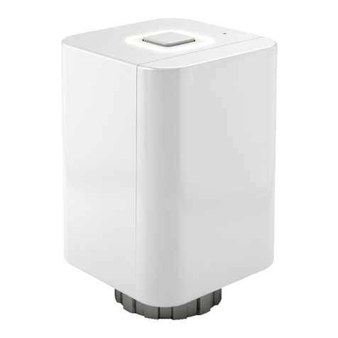
Wireless thermovalve measures the room temperature and sends it to the
Smart RF box.
•
according to set temperature and time in your phone it opens or closes the radiator valve
•
battery supply allows quick and easy installation
•
accessor
i
es: 2x AA batteries (included in the package), adapters Danfoss RAV, RA, RAVL
The unit offers a complete control over heatin
g
, switchin
g
appliances and devi-
ces, li
g
hts or blinds, shutters control or
g
ateway.
•
control and display of temperature, weekly schedule option
•
possibility to add up to 40 units of the iNELS RF Control system
•
desi
g
ned for wall mountin
g
or into an installation box
•
p
arameters: Touch 3,5“ color display, dimension 94 × 94 mm, power supply AC 230V (clips)
or the plu
g
-in adapter (included in the packa
g
e)
Kit content ......................................................................................................................................................................................................................
How does it work? ..................................................................................................................................................................................................
The range of RF signal .........................................................................................................................................................................................
Installing a wireless thermovalve ..............................................................................................................................................................
Installing a wireless touch unit ....................................................................................................................................................................
Default screen ...........................................................................................................................................................................................................
Settings .............................................................................................................................................................................................................................
Heating modes .........................................................................................................................................................................................................
Temperature adjustment ...................................................................................................................................................................................
Time programs .........................................................................................................................................................................................................
Additional settings ................................................................................................................................................................................................
Assigning other units ..........................................................................................................................................................................................
Technical parameters of RFATV-1 .............................................................................................................................................................
Technical parameters of RF Touch ...........................................................................................................................................................
Other RF units ............................................................................................................................................................................................................
Overview of other kits .........................................................................................................................................................................................
Virtual kits ......................................................................................................................................................................................................................
Notifications and their solutions ...............................................................................................................................................................
5
6
7
8
9
10
11
12
13
14
15
22
24
25
26
30
33
34
3×
1×
L
E
G
E
N
D
:
RF (Radio Frequency)
– a radio frequency signal for communication of wireless devices. It works at
8
68 MHz frequency. The signal goes through buildings which affect the signal.
Unit, Wireless unit
– it is a receiver or unit
,
which receives RF commands and controls connected
d
evices. It can be e.g. bulbs, switching socket, thermovalve etc.
Order code: 5174Order code:6307
1)
2)
3)
4)
5)
6)
7)
8)
9)
10)
11)
12)
13)
14)
15)
16)
17)
18)

76 ../
U´ 2.0
HOW DOES IT WORK?
23
Each wireless unit is numbered 1,2,3, it corresponds to the name in Wireless
touch unit (Heating 1, Heating 2, Heating 3). It is possible to connect up to 30
Wireless thermovalves.
Wire
l
ess t
h
ermova
l
ve measures t
h
e room tem
p
erature an
d
b
ase
d
on t
h
e va
l
ue set in
wireless touch unit it sends a command to o
p
en/close a thermovalve.
THE RANGE OF RF SIGNAL
brick
walls
wooden structures
with plaster boards
reinforced
concrete
metal
partitions
common
glass
60 - 90 % 80 - 95 % 20 - 60 % 0 - 10 % 80 - 90 %
com
mon
met
al
INSTALLING A WIRELESS TOUCH UNIT
In case of insufficient connection between wireless thermovalve, you have the following
possibilities:
RELOCATE WIRELESS THERMOVALVES
USE REPEATER (plug-in signal repeater) - install between wireless touch unit and wireless
thermovalve which is out of the range.
Place a wireless touch unit in the best possible position from Wireless thermovalves.
Optimal placement of Wireless touch unit is in the middle of space between each wireless
thermovalve.
Please keep in mind, that the number of walls, ceilings reduces the signal strength and thus
limitsthe range of wireless thermovalves.
Temperature °C
Command
OPEN / CLOSE
°C
C
1
WIR
ELE
SS
TOUCH
UNIT
RF T
OUCH
Heating 1
Heating 2
Heating 3
The range of RF signal is up to 200 m in the free open air.
TRANSMISSION OF RADIOFREQUENCY SIGNALS IN VARIOUS MATERIALS
REPEATER
to extend
the range
Order code: 4510
FE
Temperature regulation

98 ../
U´ 2.0
Power supply via terminals
INSTALLING A WIRELESS THERMOVALVE
Power supply
1. Open battery cover
2. Insert batteries (keep in mind the polarity)
3. Close the cover -> your RFATV-1 is ready to install
Mounting
Wireless thermovalve can be quickly and easily mounted on all common valves.
It can be installed without grime and water spots because the heating circuit is not interrupted.
1. Use an appropriate adapter, if required, and push it into the valve.
2. Screw the connector (connecting ring) on the valve or the adapter.
3. Put RFATV-1 into the connector (connecting ring) until it noticeably clicks into place.
The wireless thermovalve must be installed evenly to the connecting ring.
Auto calibration of wireless thermovalve
After placing a valve to vent and inserting batteries,
it is necessary to calibrate the valve on vent. It is
can be done by pressing „blue“ button directly on a
thermovalve (using the key). During this operation
please do not manipulate with the thermo valve. Auto
calibration is finished by a blink of green LED diode on
thermovalve.
Blue button
Green LED
Press using „the key“
Dismounting
Wireless thermo-valve can be quickly and easily
dismounted using the second side of the key.
Address
INSTALLING A WIRELESS TOUCH UNIT
Surface mounting
AC 100 - 230V / 50 - 60 Hz
Valve Connecting
ring
Wireless
thermovalve
Adapter
Power supply through adapter
(adapter is included in the package)
2.
1.
Surface mounting by sticking
The spacing between
screws on the box
Danfoss RAV:
(The attached pin should
be mounted on the valve
tappet.)
TYPE OF ADAPTER
TYPE OF VALVE:
Danfoss
RA:
Danfoss
RAVL:
TYPE OF ADAPTER
TYPE OF VALVE: TYPE OF ADAPTER
TYPE OF VALVE:
T
he spacin
g
between
screws
on
the
box
L
N

1110 ../
U´ 2.0
Date and time
1.
Touch the icon in the upper-right corner of the screen and enter a password (default settings - 1111).
Fig. 5
Fi
5
Fig. 5
Fig. 6
Fi
6
Fig. 6
Fig. 4
Fi 4
Fig. 4
Language settings
2.
The choice and settings of
required language - see Fig. 10. To
save settings press the button
OK .
Fig.
10
Fi
10
Fig.
10
Fig.
7
Fi
7
Fig.
7
Fig.
8
Fi
8
Fig.
8
DATE AND TIME
Using the the arrow keys /
firstly set the date and then click on
„Setuptime“.
AUTOMATIC SUMMER/ WINTER
CHANGEOVER
tick automatic changeover to active
thesummer/winter timechangeover
(GTM + 01:00) Fig. 8.
THE TIME FORMAT SETTINGS
Tick this box to activate automatic
time settings (12 h / 24 h mode); To
save settings press the button OK .
SETTINGSTHE DEFAULT SCREEN
Setting the clock
1.
Touch the top right corner to select the type of clock to display on the screen. An ANALOG (Fig.
2) or DIGITAL (Fig. 3) display.
Fig. 2
Fi
2
Fig
. 2
Fig. 3
Fi 3
Fig
. 3
ANALOG DIGITAL
Fig. 9
Fi 9
Fig. 9
LOCATION OF ADDRESS AND TYPE OF EACH UNITS
Fig. 1 BOX
SOCKET MODULE
005A95
Address:
00150A
Address:
005A95
Address:
CF0X50
DF0X50
CF0X50
DF0X50
CF0X50
DF0X50
Unit:
RFSA-61B
Unit:
RFSC-61/F
Unit:
RFSA-66M
THERMOVALVE
Address:
007585
THERMO
Unit:
RFATV-1
007585

1312 ../
U´ 2.0
TEMPERATURE ADJUSTMENT
To change the temperature in the heating circuit, click the button Settings (Fig. 3) and then click on
the Heating mode that you want to change (Fig. 4).
The current temperature and the set temperature will be displayed nextto the icon on the display. You
can adjust the temperature by touch on Settings (Fig.5).
Using the arrow keys / you can change the temperature to the desired one (long press on the
key arrow leads to faster shifts between figures). To save the temperature, press button OK (Fig.6).
Fig.
5
Fi
g
5
Fig.
5
Fig.
6
Fi
g
6
Fig.
6
Fig.
3
Fig
3
Fig.
3
Heating 1
Heating 2
Heating 3
Fig.
4
Fig
4
Fig.
4
Heating 1
Heating 2
Heating 3
HEATING MODE
The menu Temperature regulation (Fig. 1) is used to control and set the heating mode. Touch on
Temperature regulation and then you will see the list of Heating Circuits (Fig. 2). Wireless thermovalves
are preset in Wireless touch unit (Heating 1, Heating 2, Heating 3). It corresponds to the number 1,2,3
marked on Wireless thermovalves.
Normal mode
Sleep mode
Party mode
Anti-frost mode is used to keep the minimum target temperature in the range 5 - 15°C.
AUTO The heating program is used to set the heating mode for the entire week.
Holiday mode is used for temporary interruption of heating program or another mode from
Temperature Regulation.
To activate the mode for individual Heating circuit it is necessary to click on the individual Heating
modes (highlighted in red).
Fig. 1
Fig 1
Fig. 1
Fig. 2
Fig 2
Fig. 2
Heating 1
Heating 2
Heating 3
These modes offer you a preset temperature which can be amended for
individual Heating circuit according to your requirements.
}

1514 ../
U´ 2.0
ADDITIONAL SETTINGS
Holiday mode
1.
Holiday mode is used for temporary interruption of the heating program.
Click on the button and then on for the chosen Heating circuit (Fig. 2). To start (switch on) the Ho-
liday mode please insert the following information: date, month and year and then press the button
OK (Fig. 3). Then the following screen will be displayed: Switch OFF to set the termination of the
Holiday mode. Click on the OK button.
To display the set Holiday modes, click on the „Overview“ (Fig.4).
Note: You can assign up to 5 time intervals in the Holiday mode. But programs should not have over-
lapping time ranges. Saving mode is active during the Holiday mode.
To delete the individual Holiday mode, click on the bar belonging to the program (Fig.5), then press the
icon Trash in the lower part of the screen. If you do not mark any holiday mode, then by clicking
on the icon Trash , all Holiday modes will be deleted.
Fig.
3
Fig.
3
Fig.
4
Fig.
4
Fig.
5
Fig.
5
Note: The set heating mode remains until the next change in your Heating program.
Fig.
2
Fig.
2
Heating 1
Heating 2
Heating 3
TIME PROGRAM
Click the Settings and then click on AU TO for the chosen Heating circuit (Fig.1, Fig.2). You can change a time
by touching on the time interval (hours/minuts). Using the arrow keys / you will set the ON time and
OFF time. Using the arrow keys next to the icon you will adjust the target temperature.
Note: You can create up to 5 heating programs for one day. But programs must not overlap in time (should
not have overlapping time ranges) - (Fig.5). By long press of the arrow key you can switch back and forth
between the figures more quickly.
By touching on the individual day (Mo-Su) you will activate Heating program for the chosen day (Fig.5, Fig.6).
- heating ON, - heating OFF.
To confirm the set program click the OK button. In case that you want to set another Heating program,
please continue programming.
Fig. 8
Fig. 8
Fig. 3
F
ig. 3
Fig. 7
Fig. 7
Fig. 4
Fi
g. 4
Fig. 5
Fig. 5
Fig. 6
F
ig. 6
Fig. 1
Fi
g. 1
Heating 1
Heating 2
Heating 3
Fig. 2
Fi
g. 2
Heating 1
Heating 2
Heating 3
After clicking the Daily overview (Fig.4), you will see all set Heating programs for each day. After clicking on
individual days (PO-SU), there will be a list of individual programs. Using these arrows you can change
time of your Heating program / Set temperature (Fig. 5, Fig. 6). Use this button to delete the chosen
Heating program. Click on the Weekly overview (Fig.7) to see Weekly overview of heating programs for each
heating circuit. Use button to delete the whole Weekly program (Fig.8).
Fig.1
Fig.
1
Heating 1
Heating 2
Heating 3
THE PRECEDENCE OF HEATING MODES
1ANTI-FROST MODE
HOLIDAY MODE
AUTO HEATING PROGRAM
SAVING MODE NORMAL MODE PARTY MODE
2
3
4
Heating 1 Heating 1
Heating 1 Heating 1 Heating 1 Heating 1

1716 ../
U´ 2.0
ADDITIONAL SETTINGS
Click on the „Settings“ and then on the „Menu“ (create a title) to edit the title of the heating circuit
(Fig. 2).
By pressing the icon the menu will be displayed, then select the section whose title you want to
change (Fig. 4) – in this case Temperature regulation. Mark the Heating circuit by touch (Fig. 5) and
then edit the text by using keyboard.
Press the OK button to save (Fig. 6).
Fig.
3
Fi
3
Fig.
3
Fig.
4
Fi
4
Fig.
4
Fig. 5
Fi
5
Fig
.
5
Heating 1
Heating 2
Heating 3
Fig. 6
Fi
6
Fig
.
6
Heating 1
ADDITIONAL SETTINGS
Open window detection2.
The function of Open window detection (Fig.4) monitors the sharp temperature drop and close Wireless
thermovalve to a preset time. You can choose 3 sensitivity levels of open window detection or switch the
function off (Default Switch OFF).
Low sensitivity – temperature drop by over 1,2°C/min.
Medium sensitivity – temperature drop by over 0,8°C/min.
High sensitivity – temperature drop by over 0,4°C/min.
To set open window detection press the button Settings (Fig. 1). Then click on the Heating mode (for the
chosen Heating circuit) that will be adjusted (Fig. 2).
Window detection (Fig. 5) a green dot indicates the current heating interruption for a specified
period of inactivity
a red dot indicates that function of window detection is not active
The period of inactivity - non-operating (Fig. 6) – used to set the period of inactivity after open window
detection.
Status (Fig. 5) – Status 0 indicates that Wireless thermovalve is functioning correctly.
Fig. 4
Fi
4
Fig. 4
Fig. 6
Fi
6
Fig. 6
Fig. 3
Fi 3
Fig
. 3
Fig. 1
Fi 1
Fig
. 1
Heating 1
Heating 2
Heating 3
Fig. 2
Fi 2
Fig. 2
Heating 1
Heating 2
Heating 3
Fig.
2
Fi
2
Fig.
2
Fig. 1
Fi
1
Fig
. 1
Edit title of heating circuit3.
Fig. 5
Fi
5
Fig. 5

1918 ../
U´ 2.0
ADDITIONAL SETTINGS
Pairing / removing Wireless thermovalves5.
Used to pair wireless thermovalves with switching unit, that controls the heating source (mainly boiler).
It avoids a situation when your boiler is working but all the radiators are closed.
Click on the Settings / Programming / Temperature regulation and select the Assigned receivers (Fig. 2).
The list of all assigned Heating circuits will be displayed.
By tapping on the name, the following options will be displayed: Removing / Pairing / Paired with... /
Address change (Fig. 6). Using the arrow keys you can double-check the name and address of the
assigned Wireless thermovalve (Fig. 4,5).
Fig. 4
Fi
g
.
4
RFATV-1
Fig. 1
Fi
g
.
1
Fig. 2
Fi
g. 2
Fig. 5
Fig.
5
ADDITIONAL SETTINGS
Others
4.
Click on the Setting / Others and other settings of
Wireless touch unit will displayed.
Lock the keyboard: it helps to prevent accidental
or unwanted control Wireless touch unit (Fig. 3).
Double tap on the lock icon to unlock default screen
(Fig. 4).
Display menu: you can specify which items will
be shown in the main menu (e.g. just Dimming,
Switching and Detectors - Fig. 5-6). The icon means that these items will not
be shown in the Main menu.
Temperature regulation (Fig. 8): Celsius and Fahrenheit degrees (°C to
°F), heating hysteresis setting: the lower and upper limits of the range 0.5. -
5°C (Fig. 9); the offset setting (to compensate inaccuracies in the temperature
measurement) in the range from -5 to +5°C; thermostat: Heating/Cooling.
Home screen: set Favorites panel to your home screen (Fig. 10, 11).
Left = 1. option, middle = 2. option, right = 3. option.
pic.
11
p
i
c.
11
pic.
8
p
i
c.
8
pic.
9
p
i
c.
9
Fig.
7
Fig.
7
pic.
10
p
i
c. 1
0
Fig. 6
Fig
.
6
Fig. 5
Fig.
5
Fig. 4
Fi
g
.
4
Fig.
3
Fig.
3
Fig. 1
Fig. 1
Fig. 3
Fi
g
.
3
Heating 1
Heating 2
Heating 3
i
ng 2
g 2
i
n
ng
g
g
g
g
3
3
3
3
3
3
TO REMOVE
Used to remove Wireless thermovalve (it will not be assigned using short
name - Heating 1, Heating 2, Heating 3)
Thanks to this option you can combine Wireless thermovalves with switching
actuator RFSA-61M, RFSA-61B or RFDAC-71B. The wireless thermovalve mea-
sures the current temperature and switching actuator, based on the measured
temperature, will switch ON/OFF the heating source. In case that switching
actuator is paired with more Wireless thermovalves, so then the boiler will be
turned off/on after the desired temperature is recorded by all thermovalves.
The switching unit paired with Wireless thermovalve will be shown. You
can remove the paired unit by clicking on the unit name.
PAIR WITH ...
PAIRED WITH ...
Used to change the address of Wireless thermovalve.
ADRESS CHANGE
Fig. 6
Fig.
6
RFATV-1
Fig.2
Fig
.
2

2120 ../
U´ 2.0
ADDITIONAL SETTINGS
Change password
8.
Change Password (PROG.): used to change a password which allows you to go to a programming
mode. By entering a password - Fig. 5 (default password 1111), the screen to enter a new password will
appear - where you type and confirm a new password. Press OK to save the new password (Fig. 6).
Reset the device: To reset a device use the password 1234 (Fig. 7). This password cannot be changed.
By inserting a password and confirmation YES (Fig. 8) you will restore the unit to its factory settings.
Fig.
6
Fi
6
Fi
g.
6
Fig.
7
Fi
7
Fi
g.
7
Fig.
8
Fi
8
Fi
g.
8
Fig.
4
Fi
4
Fig
.
4
Fig.
5
Fi
5
Fig
.
5
Fig.
3
Fi
3
Fig
.
3
ADDITIONAL SETTINGS
Fig. 3
Fi 3
Fig. 3
Fig. 1
Fi 1
Fig. 1
Fig. 2
Fi 2
Fig. 2
Indication of a low-battery condition of Wireless thermovalve
6.
Low battery indicator of Wireless thermovalve appears on the screen (Fig.1). Press the battery to
display the unit name. Use arrow keys to switch between the name and the address of the unit
(Fig. 2-3). More about the address location can be found on the page 10.
Fig. 1
Fi 1
Fig. 1
Fig.
2
Fi
2
Fi
g.
2
The display
7.
Background: select the type of screen background color (black, blue, green, purple).
Screensaver: the desired brightness (25%, 50%, 75%, 100%) will be activated after a set amount of
time after the last touch is detected (15s, 30s, 1min, 3min).
Sleep mode: set the time after which RFTouch screen unit goes to sleep after last touch - the screen goes
dark (0min, 10min, 15min, 20min)
Calibrating the display: the cross buttons appear in every corner of the screen, required to tap twice.
Calibration will be performed. Display calibration can also be started by resetting the unit or disconne-
cting the power supply from the unit; after reconnecting again, the RF Touch logo will appear on the
display - hold the logo for more than 3s to activate calibration – touch logo longer than 3 seconds and
calibration will be activated.
Heating 1

2322 ../
U´ 2.0
ASSIGN OTHER UNITS
Menu (create names)
1.
Press the ADD icon (Fig. 2) to show a list of sections (Fig. 3)
Temperature regulation Switching Dimming Blinds Shutters Quickcontrol
Choose the section where you want to add new name for your device
and type your own text (max. 20 characters).
Fig. 2
Fig. 2
Fig. 4
Fig. 4
Fig. 1
l
Fig. 1
Fig. 3
Fig. 3
ASSIGN OTHER UNITS
Programming / assign a new device2.
Click on the Add/Assing new (Fig. 3). A list of units from selected section will be shown (Fig. 4). Click
and select the actuator which you want to assign to Wireless RF Touch. Enter the address of actuator
you want to assign - Fig. 5 (address indicated on the actuator). Confirm with OK .
From the menu location, select the name to which the actuator will be assigned (Fig. 6, Fig.7).
Note: Only one name can be assigned to each actuator. When programming, wireless actuator must
be connected with the installation.
COMMMUNICATION TEST (Fig. 8)
used to detect and display the current status of the RF signal between the
RF Touch and programmed actuator.
Press Start (Fig. 9) to initiate the test, the current status of the signal is
displayed in percentage. If it is less than 20 %, please relocate the unit or
use Repearer (RFRP-20).
Press Return to Programming to get back to the main menu of programming.
Note: Communication test can not be performed for battery powered devices.
Fig. 5
Fig. 5
room 1
Fig.
7
Fig.
7
Fig.
5
Fig.
5
Fig.
3
Fig.
3
Fig.
3
Fig.
4
Fig.
4
RFATV-1
Fig.
8
Fig.
8
Fig.
9
Fig.
9
Fig.
6
Fig.
6
Fig.
2
Fig.
2
Heating 1
Heating 2
Heating3
at
ing
ng
g
2
2
t
ing
ng
ng
g
2
2
t
ing
ng
g
2
2
t
ing
ng
g
2
2
at
t
i
in
n
n
n
n
ng
g3
g3
g3
g3
g3
Used to assign the wireless units to menu you created in the previous step (Menu - create names). In
the menu „Settings“ choose Programming (Fig.1). Units are divided into sections for which they are
intended. According to the actuator‘s type, select a required section - see table below.
Menu (create names) used to add, rename, edit or remove the names of Wireless
units.
The name of wireless units corresponds to the name of controlled appliance (the
kitchen light, the living room light, garage, ...). Creating names is important for
successful programming of the wireless RF Touch.
RF CONTROL ACTUATOR SECTIONS
TEMP. REGULATION SWITCHING DIMMING SHUTTERS DETECTORS
RFSTI-11B/G RFSA-11B RFDA-11B B RFJA-12B/230V JA-81M / 82M
RFTI-10B INX RFSA-6X* RFDA-71B RFJA-12B/24V DC JA-80P
RFTI-10B OUTXX RFDAC-71B B RFDAC-71B
RFTC-10/G RFSAI-61B RFDEL-71B
RFATV-1 RFUS-11 RFDSC-11
RFUS-61 RFDSC-71
RFSC-11
RFSC-61
Fig. 1
Fig. 1

2524 ../
U´ 2.0
TECHNICAL PARAMETERS
Supply voltage: 2 x 1,5V batteries
Control
868 MHz
Battery life:
RF command from the transmitter:
Range in open space:
Frequency:
0 up to +50 °C
Working position:
Operating temperature:
any
Protection:
Dimensions: 65 x 65 x 48 mm
M 30 x 1,5
IP 40
Piston stroke:
Controlling force: max. 100 N
EN 60730
End cap of thermo-valve:
max. 4 mm
Relating standards:
RF Touch
up to 100 m
Other data
1 year
TECHNICAL PARAMETERS
Display
color TFT LCD
Resolution:
Side proportion:
Type:
from the rear 100 - 230V AC, from the side 12V DC
Input power:
Supply voltage/rated current:
max. 5W
Power supply terminals:
Range: 100 m
1 m
A1 - A2
Frequency:
Connection: no-screw push-in terminal box or jack plug (diameter 2.1 mm)
max. 2.5 mm2 / 1.5 mm2with a hollow
Min. distance RF Touch - Actuator:
868 MHz
Cross-section of connecting wires:
320 x 240 pixels / 262 144 colors
3:4
Power supply
52.5 x 70 mm
Backlighting:
Touch area:
Visible surface:
active (white LED)
resistive 4-conductor
3.5´´
Control:
Diagonal:
touch
Control:
Connection
Operating conditions
0 up to +50 °C
Storage temperature:
Protection:
Operating temperature:
-20 up to +70 °C
IP 20
III.
Contamination degree:
Operating position:
Overvoltage category:
2
any
anywhere
Dimension:
Installation:
94 x 94 x 24
175 g
Relating standards:
Weight:
EN 60730-1
577515
Valve
Battery cover
Blue button to
calibrate
Green LED
indicators
Address
Front side Reverse side
RFATV-1 RF TOUCH

2726 ../
U´ 2.0
OTHER RF UNITS OTHER RF UNITS
SWITCHES
CONTROLLER
PICTURE DEVICE DESCRIPTION TYPE/CODE
1-channel switching unit in the box that provides higher protec-
tion level. Intended for outdoor installation suited for wet, humid
and dusty areas. Output switching contact 12A/3000W, power
supply AC 230V, 6 functions. It it possible to control up to 32 con-
trollers. Enclosure IP65, dimension 136x62x34 mm, color: grey.
SWITCH UNIT FOR OUTDOOR USE
4526
Used to control shutters, blinds, awnings, garage doors, gates,
skylights - all devices that can be controlled in two directions. It
can be controlled by up to 32 push-buttons of any controller. In-
tended to be mounted into an install. box or tothe motor housing.
Power supply AC 230V, switching capacity for the contact is 8A.
SWITCH UNIT FOR SHUTTERS (CONTACTLESS)
4682
PICTURE DEVICE DESCRIPTION TYPE/CODE
Quick solution for wireless control of plug-in appliances, when
the switching socket is installed between the existing socket and
a plug-in appliance. Output contact 16A/4000W, 6 functions, it is
possible to control upto 32 controllers. Dimen.: 60x120x84 mm.
SWITCHING SOCKET
4560
1-channel and 2-channel switching actuator intended to be mounted
into an installation box, that can switch any device. It can control up
to 32 controllers. Power supply 230V. RFSA-61B: Switching contact
16A/4000W. RFSA-62B: 2 independent 8A/2x2000W contact.
WIRELESS SWITCH UNIT - 6
4499
(4770)
PICTURE DEVICE DESCRIPTION TYPE/CODE
DIMMERS
For dimming of lamps and lighting construction, when the swit-
ching socket is installed between the existing socket and the lamp.
It allows you to dim incandescent bulbs, halogen lamps, dimmable
energy saving bulbs and modern LED lighting sources upto 300 W.
DIMMING SOCKET (MULTI-FUNCTION)
4594
Wireless multifunction (7 functions) dimmer used to dim
incandescent bulbs, halogen lamps, ... The type of lighting
source is selected using the rotary switch. Intended to be
mounted into an installation box. Power supply AC 230V.
UNIVERSAL DIMMER (INBUILT)
4512
Dimmer intended to be mouned in a switchboard to control colou-
red RGB. Strips with max. power 70 W / channel that corresponds to
approximately 10 m of RGB strip. Power supply DC 12-24-V, option
of color blending mode, controlthrough keychain, RF Pilot or App.
DIMMER FOR COLOURED (RGB) LED STRIPS
4681
6-channel switching actuator intended to be installed in the swit-
chboard contains 6 independent 8A contacts, that can switch any
device connected in switchboard. Power supply 230V. The antenna
AN-I included in the package can be replaced by external type AN-E
what eliminates the influence of metal door of switchoboard.
WIRELESS SWITCH UNIT - 6 OUTPUTS
4282
4897
Wireless multifunction (7 functions) dimmer used to dim
incandescent bulbs, halogen lamps, dimmable energy saving
bulbs and modern LED lighting sources up to 600W of power.
Power supply AC 230V.
UNIVERSAL DIMMER
RFSC-61
RFSA-61B
(RFSA-62B)
RFSA-66M
RFUS-61
RFJA-12B
RFDSC-71
RFDEL-71B
RFDA-73M/
RGB
RFDEL-71M
PICTURE DEVICE DESCRIPTION TYPE/CODE
Each of the 2 independent push-buttons can control any
number of wireless units (switches, dimmers, shutters). In
the design of LOGUS90 switch (plastic, glass, metal, wood,
stone). Battery-powered 3V/CR2032. Color: white.
RFWB-20/G
4037
4 BUTTON CONTROLLER - KEYCHAIN
4375
Wireless controller sends a command to switch ON/OF or dim
any wireless device after pushing the button. You can control
independently up to 4 devices. By one touch, you can switch
ON any number of units at once. Battery-powered 3V/CR2032.
Universal controller with display enables you to comfortably
control wireless units, using all their functions. It enables
to create rooms, scenes and favorites sections/folders. It is
possible to preset up to 40 units. Battery-powered 2xAAA.
WIRELESS REMOTE CONTROLLER WITH DISPLAY
4376
Transmitter serves as the contact converter of external device
to the commands for wireless units. It contains 2 inputs, that
can be switched ON permanently (by push-button or switch).
Battery-powered3V/CR2477, into aninstallation box.
WIRELESS CONTACT CONVERTER
4175
RF KEY
RF PILOT
RFIM-20B
WIRELESS WALL CONTROLLER
Each of the 4 independent push-buttons can control any
number of wireless units (switches, dimmers, shutters). In
the design of LOGUS90 switch (plastic, glass, metal, wood,
stone). Battery-powered 3V/CR2032. Color: white.
RFWB-40/G
4060
WIRELESS WALL CONTROLLER
SWITCHES

2928 ../
U´ 2.0
OTHER RF UNITSOTHER RF UNITS
TEMPERATURE CONTROL
SYSTEM UNITS
4510
PICTURE DEVICE DESCRIPTION TYPE/CODE
Used to control up to 40 wireless units. Besides switching, cont-
rolling and dimming, it includes thermostats with weekly progra-
mming and it also enables to connect detectors. In the size of the
switch, with frames in the LOGUS90 design intended for surface-
-mounted installation. Power supply 230V. White color.
WIRELESS TOUCH UNIT - SURFACE MOUNT
RFTW-AWH-
-BWH-CWH
The mediator between your controller and wireless units controlling
lights, heating, shutters, sockets and other appliances. eLAN-RF-003:
It is connected to LAN network of your router and it is placed to ensure
the visibility to other controlled units. eLAN-WI-003: App for contro-
lling is free to download from GooglePlay or iTunes Store.
SMART RF BOX,
5173
(4872)
SMART WI BOX
IP CAMERA FOR OUTDOOR USE
6703
MULTIFUNCTIONAL GSM COMMUNICATOR
GSM gate intended to be mounted in a switchboard enables a re-
mote control of wireless units via SMS text message. It can also
send SMS text message containing information about the status
of wireless units. It contains 4 binary inputs for signals and 2 relay
outputs 8A/2x2000W to switch directly the unit.
4604
Indoor color camera D-Link DCS-933L/E can be easily conne-
cted to LAN through cable or to wireless WiFi network. It is
possible to monitor up to 10 cameras in the App. Resolution
640x480, dimension: 80x115x80mm, power supply: inclu-
ded in the package 5V/1A.
RF TOUCH - W
eLAN-RF-003
(Wi-003)
iNELS CAM
RFGSM-220M
Repeater in the socket design, that is used to increase the
range of signal or in case of low signal between controller
and unit. It is possible to repeat the signal of up to 20 units.
REPEATER TO EXTEND THE RANGE RFRP-20
LIGHTING
PICTURE DEVICE DESCRIPTION TYPE/CODE
6630
Coloured RGB strip, 7.2W/m (30 LED chips / m), length 5 m, width
11mm, outdoor-proof design, also designed for installation on alu-
minium rails, adhesive tape, it can be shortened by 10 cm, luminous
flux of 660 lm/m, control by RFDA-73M dimmer, power supply 12V.
COLOURED RGB LED STRIP, 5 METERS
6589
Power supply 230V/12V/60W to power 5m of RGB strip.
Intended for outdoor use (IP67), dimension 162,5 x 42,5
x 32 mm.
POWER SUPPLY FOR 5 M RGB STRIP
7,2W, RGB,
30LED/M
DC 12V/5A
60W
This RGB LED bulb consists of 3 color chips which can mix up
any color at different temperatures. Bulb has a built-in rece-
iver and dimmer, so it can be easily replaced for the original
bulb. Other functions: colorful scenes, brightness setting etc.
WIRELESS RGB BULB
4931
RF-RGB-
LED-550
This bulb comes in both warm and cool white, it has built-
-In wireless receiver and dimmer, it can easily be placed
in any existing base and control by any controller.
WIRELESS WHITE BULB
4936
RF-WHITE-
LED-675
PICTURE DEVICE DESCRIPTION TYPE/CODE
Digital thermostat in the design of the LOGUS90 switch (plas-
tic, glass, metal, wood). It measures the room temperature and
according to the set heating program (weekly mode) it sends
commands to the switching unit (heating device). Battery-po-
wered (2xAA). It is possible to control up to 4 heating circuits.
WIRELESS TEMPERATURE CONTROLLER
RFTC50/G/
BR/BR
Temperature unit in the design of LOGUS90 switch. It measures the
temperature and switch a heating circuit at the same time. Relay
contact 8A/2000W, power supply 230V, the possibility to connect
an exter. temperature sensor. It is possible to connect up to 30 units.
SWITCH UNIT WITH A TEMPERATURE SENSOR
RFSTI-11/G/
BR/BR
RFATV-1
6307
Wireless thermovalve measures the room temperature and
sends it to the Smart RF box, that compares the temperature
records with the set temperature and according to set pro-
gram it sends a command to open or close the radiator valve.
RFTC-50/G
WIRELESS THERMOVALVE
RFSTI-11/G
PICTURE DEVICE DESCRIPTION TYPE/CODE
Internal or external sensor measures the temperature starting
from -20 up to 50°C. Intended to be mounted into an installati-
on box, but it can be also placed anywhere. Recommended ex-
ternal sensor - TC/TZ 3-6-12 m. Battery-powered 3V/CR2477.
WIRELESS TEMPERATURE SENSOR
3175
THERMODRIVER
6602
Electric thermodrive to be mounted on the radiator valve
(including adapter VA80 for valves Heimeier, Oventrop,
Schlösser, Herb or Onda. (M30 x 1,5)). Power supply: 230 V
(closed without power).
RFTI-10B
TELVA/230V
TEMPERATURE CONTROL

3130 ../
U´ 2.0
THE OVERVIEW OF OTHER KITS
THE OVERVIEW OF OTHER KITS
It has never been easier to set the appropriate ambience for reading a book, watching a movie
or a party with friends. All you need is wireless bulbs and Smart RF box. Then you can control
every device from the comfort of your smartphone, tablet or smart TV. You can control not just
colored or white light bulbs, but other appliances too.
THE GAME OF LIGHTS
SMART RF
BOX
COLORED
WIRELESS
BULB
1×
3×
KIT TO CONTROL LIGHTS VIA SMARTPHONE
REMOTE HEATING
SMART RF
BOX
WIRELESS
THERMOVALVES
1×
3×
Includes 3 wireless thermovalves that are installed instead the standard radiator valves. They me-
asures the room temperature and send it to the Smart RF box. Smart RF box compares it with the
temperature set along with the time schedule in the application of your phone and sends a com-
mand to open or close the valve. You can always turn on the heating circuit via app, whether you‘re
at home, or just going to visit your cottage and don´t want to come to unheated place.
KIT TO CONTROL HEATING VIA SMARTPHONE
ORDER CODE: 5162
ORDER CODE: 5159
This kit enables convenient and quick control of heater, oil heater, panel heater or portable air
conditioner. Just plug the controlled device into switching socket and appropriately place your
controller RFTC-50G. The desired temperature is set on the controller, that compares it with
the current record and it sends a command to turn the device ON.
EASY HEAT REGULATION
KIT FOR WIRELESS TEMPERATURE REGULATION IN THE HOME
TEMPERATURE
CONTROLLER
SWITCHING
SOCKET
1×
1×
ORDER CODE: 5160
RADIO & MUSIC IN THE SWITCH
LARA is a music and internet radio player. We have registered 40 favorite Czech radios stati-
ons as presets stations, but you can easily change it using configurator. LARA plays the music
stored in the NASA storage or in the external source (phone, MP3 player) connected through
cable on the front panel of device. Inbuilt amplifier allows direct connection of speakers (in
the same LOGUS 90 design) or allows connection of external in-wall or ceiling speakers.
KIT FOR CONROLLING MUSIC, WHICH PERFECTLY FITS IN YOUR HOME´S INTERIOR
ORDER CODE: 5160
LARA
RADIO
SPEAKERS
1×
2×

3332 ../
U´ 2.0
THE OVERVIEW OF OTHER KITS
ONE CONTROLLER FOR ALL
KIT FOR CONTROLLING IR DEVICES VIA A SMARTPHONE
YOUR HOUSE UNDER „THE THUMB“
CONTROL YOUR HOUSE VIA A SMARTPHONE
Thanks to IR smart box, you can control home appliances via a Smartphone. Thus you no longer
need a bunch of controllers, you do not have to look for them, and you do not need to replace
the battery. You always stick your phone in your pocket, always at hand. Moreover, you can
control devices which are placed in another room (e.g. you can turn off TV in the children room).
The kit “House under the thumb” which you hold in your hands is the basic starter kit for all
of you, who would like to make your home more comfortable. The starter kit consists of 2 x
colored wireless bulbs, 1 x switching socket and 1 x camera, what allows you to try the basic
units of iNELS RF Control – wireless solution. Everything is preset to ensure fast and easy
installation.
IR TRANSMITTER
3×
SMART IR
BOX
1×
SMART RF
BOX1×
COLORED
WIRELESS
BULB2×
WIRELESS
SWITCHING
SOCKET1×
CAMERA1×
ORDER CODE: 5163
ORDER CODE: 5162
VIRTUAL KITS
UNDERFLOOR HEATING - BY WATER
A
ny wireless temperature re
g
ulator measures the room temperature, it compares with set temperature
and time pro
g
ram, then sends a command to switch on the units. Based on the command from temperature
r
egu
l
ator,6-c
h
anne
l
s switc
h
ingunitisa
bl
e to contro
l
up to 6 t
h
ermova
l
vescorrespon
d
ingto
h
eating circuits.
KIT CONSISTS OF:
Wireless temperature controller RFTC-50/G, wireless switch unit (6 outputs) RFSA-66M,
thermodriver TELVA/230V.
UNDERFLOOR HEATING - BY ELECTRICITY
T
emperature and switching unit (two in one) measures the
fl
oor temperature via external sensor
(inbuild). Then it sends data to wireless touch unit RF Touch, which com
p
aresitwiththetem
p
erature
s
etalon
g
with the time schedule and then sends a command back to switch on/switch off the heatin
g
circuits. It is possible to connect up to 4 temperature/switching units
.
Advice 1) If just one reference temperature is enou
g
h for you, so then it can be measured by tempe
-
r
ature sensor RFTI-10B and to switch up to 6 independent heatin
g
circuits you can use 6-channel
s
s
witching actuator RFSA-66M.
Advice 2) The wireless unit RF Touch can be replaced by Smart RF box and all can be controlled vi
a
y
our smartphone. Both solution can be used to
g
ether.
AGAINST THE FLOOD
A
wireless sensor monitors the water leaks or floodin
g
in the critical places (basement, pits, shafts,
b
athroom, laundry,...) and sends immediately a command to the switchin
g
unit to close the solenoid valve
of the main water supply. You can be also informed of that accident throu
g
h GSM
g
ateway by sendin
g
SMS text messa
g
es.
COLORED RGB LED STRIP
T
he app in your smartphone can send (through smart RF box) the commands to the dimming unit to
w
hich the RGB strip is connected. From your app it is possible to switch ON/OFF, to set the color or
r
un the scene of automatic color blending.
Advice 1) The colored RGB strip can be controlled throu
g
h RF Pilot, by controllers RFWB-20/40, RF key,..
.
Advice 2) If you do not want the colored RGB strip, we can replace it by monochromatic (warm white, cool whi
-
t
e, red, ...). Then you can connect 8 m of monochromatic strip (power 7,2W/m) to RFDA-73M to each output.
Smart RF box, dimmer RFDA-73M, 2 x 5m coloured RGB strip 7.2W/m, power supply 230V/
12V/100W.
KIT CONSISTS OF:
The virtual kit is a set of wireless units that are packed individually (as an individual product), but on
the other hand they are preset together (they are meant to work together) to ensure simple installa-
tion. They are offered at a discounted price and it is not possible to separate any unit from this price.
KIT CONSISTS OF:
Switch unit RFUS-61, wireless flood detector RFSF-1B,flood probe FP-1.
KIT CONSISTS OF:
Switching actuator with thermosensor RFSTI-11/G, Wireless touch unit RF Touch.
We recommend: solenoid valve: MPW SS 304 - 1/2 (3/4) 230V AC.

3534 ../
U´ 2.0
NOTIFICATION AND THEIR SOLUTIONS
Upozornění Postup
Notification Procedure
S
witch-ON date ma
y
not be the same as the
s
witch-OFF date.
A
ll 5 programs are already occupied.
S
witch-ON date may not exceed the switch-
-
OFF
d
ate.
New settin
g
s required
.
No other program can be entered
.
New settings required
.
New settings required
.
N
o unit assi
g
ned to the room.
D
isplay incomplete - control impossible.
E
PROM memory error!
T
his
g
roup is already assi
g
ned.
S
etting of program for midnight and over
m
idni
g
ht - at the time of 00:00 there is not
a
ny action of the actuator.
A
T45 circuit error
!
Please
contact
the
manufacturer.
Please
contact
the
manufacturer.
Calibrate the device (unplug the power supply from
device, after reconnectin
g
hold the lo
g
o of RF Touch,
calibration will be completed by double tappin
g
the
cross buttons, which appear sequentially in each
corner of the screen
).
Setting of time over midnight: set the required
switch-ON time and set the required switch-OFF
time on 00:00, next day set the switch-ON time on
00:00 and set the required „switch OFF“ time
.
Settin
g
of time for midni
g
ht: set the required switch-ON
time and set the required switch-OFF time on 23:59
.
P
l
ease contact t
h
e manu
f
acturer.
F
or
g
ot your password? P
l
ease contact t
h
e manu
f
acturer
f
or
f
urt
h
er in
f
or
-
mat
i
on
.
I
mpossible to control display.
Forced calibration is performed when restartin
g
RF
Touch and then hold your fin
g
er on (screen) RF Touch
lo
g
o
.
NOTIFICATION AND THEIR SOLUTIONS
RF TOUCH UNIT NOTIFICATIONS
Notification is displayed in case of incomplete, inaccurate or incorrect entry information.
Notification
Savin
g
failed.
Delete failed
.
Up to 40 rooms may
b
e
d
e
f
ine
d.
Two time programmes overlap within a
s
ingle day
.
N
o unit assigned.
Repeat entry
.
Repeat entry
.
No more than 40 device names may be entered
.
New settin
g
s required
.
No other programme can be entered
.
Assign the requested unit
.
Procedure
N
o time pro
g
ramme available within a
s
ingle day
.
Switch-ON time may not exceed the
switch-OFF time
.
Unit already assigned to the room.
Select
another
room.
N
o day selected.
The address has alread
y
been selected in the
unit list. Choose another address
.
This room has already been defined in the
g
roup
.
New settin
g
s required
.
One actuator can be assigned to one device name
(except for Quick Control
)
New settings required
.
Enter correct information
.
E
nter
correct
information.
E
nter a new name
.
The address information must be com
p
lete
.
„xxx“ - displayed instead of temperature. Actuator not programmed, actuator/sensor defect,
communication failure
.

Manufacturer:
ELKO EP, Ltd. / Palackeho 493
Holešov - Všetuly 769 01 / Czech Republic
phone: +420 800 100 671 / e-mail: elko@elkoep.com
www.elkoep.com
This manual suits for next models
2
Table of contents
Other Elko Control Unit manuals
Elko
Elko iNels RFATV-2 User manual

Elko
Elko iNels RFATV-2 User manual

Elko
Elko iNels RFATV-2 User manual
Elko
Elko EST3 User manual
Elko
Elko RF Touch User manual

Elko
Elko ATV-1 User manual

Elko
Elko iNels RFATV-2 User manual

Elko
Elko iNels RFATV-2 User manual

Elko
Elko iNels RFATV-2 User manual

Elko
Elko EST3 User manual
Popular Control Unit manuals by other brands
WAGO
WAGO SPEEDWAY 767 Series manual

Sony
Sony MB0402C2 user manual
Viessmann
Viessmann EM-EA1 extension Installation and service instructions
Argo-Hytos
Argo-Hytos EL7-I Series instruction manual
DeZurik
DeZurik APCO CVS-6000 Installation, operation and maintenance manual

Gascat
Gascat BRISE PLUS Installation & operation manual
