Toptec FUTURE LITE 20 Wide User manual

Assembly Instructions
20 - 30 Wide
TopTec Products, LLC
7601 Highway 221
Moore, SC 29369
Phone: (800) 845-2830
Fax: (800) 921-7750
e-mail: [email protected]
www.eventtec.com
AIFL 2030 1101

Assembly Instructions
20 - 30 Wide
THANK YOU FOR PURCHASING A TOPTEC TENT
If you have questions about the installation, maintenance or disassembly, please call us at (800) 845 - 2830.
Our goal is that you are satisfied with our products. Please read this manual carefully and follow all instructions contained
herein. Please note that the installer is responsible for the site selection, installation and use. Do not erect during inclement
weather and follow all safety procedures during the installation process.
Please contact all utility companies for underground services. In many states, the utilities work together and have formed a
Utility Locating Service. It is your responsibility to locate all underground services, including speaking to the owner about
irrigation, pool and other special services the property owner may have installed.
To provide the quickest possible service, please fill in the information below so that we can efficiently help you should any
problem arise.
FUTURE LITE SERIES TENT
FRAME SIZE (Width x Length)
END SECTION SERIAL NUMBER
END SECTION SERIAL NUMBER
MID SECTION SERIAL NUMBER
MID SECTION SERIAL NUMBER
MID SECTION SERIAL NUMBER
MID SECTION SERIAL NUMBER
AIFL 2030 1101

Installation Instructions
20 - 30 Wide
AIFL 2030 1101
i
Table of Contents
Limited Warranty ......................................................................................................................... ii
Shipping Damages - Shortages .......................................................................................................... ii
Blackout Material ........................................................................................................................ ii
Site Survey ....................................................................................................................................... ii
Site Plan ....................................................................................................................................... ii
Recommended Tools and Equipment ........................................................................................... iii
Installation Instructions
Frame Lay Out ........................................................................................................................ 1
Building Arch Assembly .......................................................................................................... 2
Raising Arch Assembly .......................................................................................................... 3
Building Hip Rafters .......................................................................................................... 3
Building Perimeter .......................................................................................................... 3
Install Hip Pole Brace Bars ............................................................................................ 5
Adding Mid Section .......................................................................................................... 5
Building Final Mid/End Section ............................................................................................ 7
Install Leg Brace Bars .......................................................................................................... 7
Top Panel Installation .......................................................................................................... 8
Lifting Frame ......................................................................................................................... 9
Anchoring Tent ......................................................................................................................... 10
Tensioning Top Panels .......................................................................................................... 11
Installed Tent Inspection ........................................................................................................................ 11
Top Removal and Folding ........................................................................................................................ 12
Lowering Frame ....................................................................................................................................... 13
Disassemble Frame ........................................................................................................................ 13
Jack Assembly ....................................................................................................................................... 14
Illustrated Parts Listing ......................................................................................................................... 15
Parts Listing ....................................................................................................................................... 16

LIMITED WARRANTY
All new TopTec, Inc. products are warranted to be free from defects in materials and workmanship which may cause failure
under normal usage and service when used for the purpose intended. If you feel that upon the receipt of our products, a
possible defect in material and workmanship exists, contact us immediately. If after examination, TopTec, Inc. determines
that there is a defect in material and workmanship, TopTec, Inc. will bear the cost of freight both to and from the factory for
repair. It will be at the factory's discretion to repair or replace the product at no cost to you.
TopTec, Inc. is not responsible for damages which occur in shipment, weather related damage, damage caused by incorrect
use of the product, damage resulting from not using proper ground cloths nor damage resulting from the use of washing
machines. Any questions in regards to the proper installation procedures should be directed to the installation manual
provided with the product or directly to TopTec Customer Service.
SHIPPING DAMAGES/SHORTAGES
UPS Shipment: The customer is responsible for immediately inspecting merchandise and noting any damage directly with
UPS. UPS will then pickup merchandise for inspection. Do not destroy or throw out shipping container or merchandise. If
UPS determines merchandise was damaged in shipment, they will contact shipper to settle claim. It is important that you
notify shipper of any shipment damage. Credit will be issued as soon as claim is settled.
Motor Freight: TopTec is not responsible for products damaged or lost in transit. The customer is responsible for noting any
damages or shortages with the freight company upon delivery. Ownership of shipment passes to customer after it is loaded
on the truck. The customer must initiate a claim with the freight company and NOTE THE DAMAGE/SHORTAGES ON
THE FREIGHT BILL so customer can protect their right of claim. Concealed damage must be discovered within ten (10)
days and the claims made with the freight carrier. It is your responsibility to count and open all products immediately.
BLACKOUT MATERIAL
The benefits of blackout material has been well emphasized: first the tent's interior is cooler therefore the air conditioning
costs are lower at large events; secondly, stains, dirt, abrasions and patches are less noticeable since light does not pass
through the vinyl. However, blackout material can cause any puncture, hole, tent repair, even box stitching to show up as
starlights in the tops. In most cases these are not holes, only an absence of blackout film which allows the light to pass
through. If these situations occur, we have a self-adhesive Blackout Repair Kit available to solve this problem. Please
contact TopTec Customer Service for assistance.
SITE SURVEY
The major purpose of the site survey is to accomplish the following:
1. To gather all pertinent information regarding the function or event.
2. To ensure that the proper equipment is used to suit the site and function.
3. To organize the information so that it becomes an effective means of communication for all parties involved.
4. To serve as a permanent record of the entire transaction.
5. To serve as a means of ensuring that all codes and regulations are met.
SITE PLAN
The major purpose of the site plan is to accomplish the following:
1. To ensure that the tent and related equipment are installed in the proper manner.
2. To ensure that the layout conforms to local codes.
3. To locate obstructions.
4. To show access to the site.
5. To locate exit areas on tents and sidewalls.
6. To locate areas with specialized anchoring.
ii
Installation Instructions
20 - 30 Wide
AIFL 2030 1101

Installation Instructions
20 - 30 Wide
iii
RECOMMENDED TOOLS AND EQUIPMENT
Personal Safety
•Gloves - Hard Hat
Site Transport
•Hand truck for moving components
Staking Layout
•Two (2) each 100' tape measures
•Two (2) each 6" shank screw drivers for staking down tape measures
•Fast dry marking paint (preferably white)
Stake Installation and Removal
•1" capacity rotary hammer for drilling holes in pavement for stakes
•An 8 to 16 pound sledge hammer
•24" pipe wrench for spinning stakes out of wet soil
•Mechanical stake puller
Frame Assembly
•Various wrenches and other types of tools (varies according to tent size).
•Tent jacks for raising frame to install legs (minimum of two (2) for a 30' x 30' and one (1) additional jack
for each 10 ft. or 15 ft. mid section).
•Ladders - Minimum of one (1) 6 ft. step. Two (2) each is best, one (1) 6 ft. and one (1) 8 ft. or 10 ft.
depending on tent size.
Top Installation
•Ground cloths to protect the vinyl from dirt and abrasion.
•Cleaning supplies to remove any marks acquired during installation.
•"Pull Ropes" - Two (2) 75 ft. long by 3/8" diameter and a third smaller rope for a return rope.
Tool Bag
Binder with blueprints and set-up instructions; (2) each - 3/8" x 75 ft. poly rope with carabiner; (1) each -
3/8" x 75 ft. rope with carabiner; Scissors; Utility knife; 8" Cresent Wrench; Flat/Half Round File with
Handle; Pliers; Cats Paw Pry Bar; Punch; Ball Point Pens; Fifty (50) each Quick Pins; One (1) Dozen
3/8" D-Clasp Pins
Please read these instructions in advance of assembly. Always be cautious of wind and weather
conditions. Partially assembled tents are large sails in windy conditions. Always tie off frames
before installing the tops.
Check the inventory list to ensue all parts are available prior to assembly. Especially important to
the Future Lite tents are the brace bars and appropriate bolts and pins.
AIFL 2030 1101

AIFL 2030 1101
Secure with
D-Clasp Pin
Installation Instructions
20 - 30 Wide
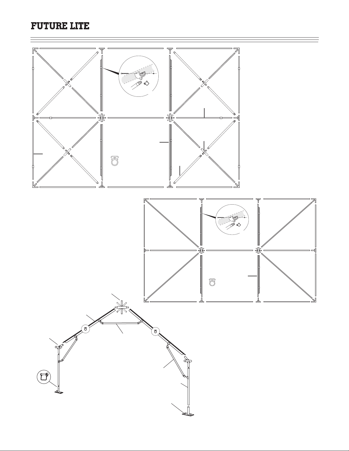
Once the site survey and site plan have been completed and the setup location determined, lay out the tubes and brackets as
shown in the drawings above. Please note the location of the end perimeter tubes (Ref. A - 30 wide only). They must be
positioned with the corner leg brace connector bracket positioned so that the leg braces can be installed after the tent is raised
and placed onto its legs. Once all the components have been laid out, assemble the frame as per the instructions on the
following pages.
A
Secure
with D-Clamp
Future Lite
30 x 45
Frame Layout
Future Lite
20 x 30
Frame Layout
A
A
A
( 1 )

Installation Instructions
20 - 30 Wide
Right side
3/8"
D-CLASP
PIN
Left side
3/8"
D-CLASP
PIN
Left side
3/8"
D-CLASP
PIN
Right side
3/8"
D-CLASP
PIN
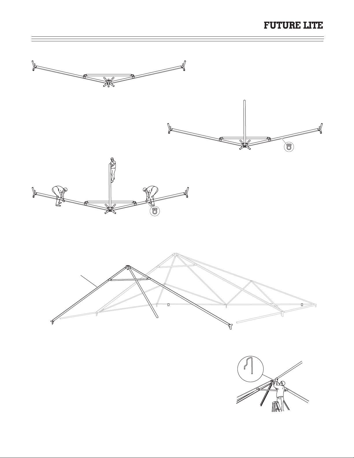
Attach the crown assembly to the Keder rafter
using a 3/8" D-Clasp pin (as shown). Repeat
procedure on the opposite side.
Next attach the intermediate brackets to the
Keder rafters (as shown) using 3/8" D-Clasp
pins.
Secure with
3/8" D-Clasp pins
Install the rafter brace bar (as shown), between
the Keder rafters using 3/8" D-Clasp pins. It
may be necessary to shift the rafter to locate
both pins.
Attach Hip Rafters (A) and (B), then attach End Rafter (C).
C
CA B
Insert Quick Pin
on A,B, and C
QUICK PIN
TOP OF CROWN
Prior to raising the arch assembly, attach both of
the hip rafters A & B (on 30' wide attach only
the upper halves) with quick pin as shown. Next
connect the end rafter (C) to the rotating spigot
and quick pin.
Tip: Before installing quick pins, determine the side
from which the top is to be installed. The flat side of the
quick pin should be facing this side, as it gives less
surface for the top to drag on.
Building Arch Assembly
Note: The 20 Wide Future Lite hip rafter is a
single piece pole.
AIFL 2030 1101
( 2 )

Rotating the arch assembly into it upright position is
easiest when there is a crew of three (3) or more. Place
the arch with the intermediate brackets at the desired
finish location and pickup the arch, as shown above and
rotate it to the upright position. One person on the end
rafter tube pulls while the other two (2) lift the arch near
the middle and work out as the arch rotates into position.
CAUTION! Once the arch is upright, one (1) person needs
to steady it (reference C) until the next steps are complete.
Build the hip rafters out by installing the hip splices into
the upper hip rafters (A & B) then quick pin. Ears on hip
splices must be pointed to the downward position. Slip
on lower half of hip rafter and quick pin to hip splice as
shown. Repeat this procedure on both sides of the arch
A
C
B
Raising Arch Assembly
I nst allation I nstr uct ions
20 - 30 W ide
A
B
C
Note: This step is eliminated on the 20 wide Future Lite frame
as the hip pole is a single piece pole.
Building Hip Rafters
Building Perimeter
Install Quick Pin
on Perimeter Pole
Perimeter Pole
Install Corner Hip Pole
Next, assemble the perimeter of the frame, starting at an
intermediate bracket on one side of the raised arch
assembly.
Tip: Install quick pins with the flat side toward the outside.
This will prevent the top from catching on the quick pin and
become damaged.
QUICK PIN
Connect corner bracket by placing perimeter tube and hip
rafter tube together into the corner bracket and quick pin;
then install perimeter tube to end intermediate on corner
and quick pin. Ensure that the end of the perimeter tube
with the leg brace mounting bracket (30 wide only) is
close to the corner bracket.
AIFL 2030 1101
Hip Rafter Lower Half
( 3 )

I nst allation I nstr uct ions
20 - 30 W ide
Connect end rafter to intermediate bracket and quick pin;
then connect perimeter tubes to intermediate bracket and
quick pin. The frame should stand by itself at this point.
font: Geo Slabserif
Next, connect the perimeter tube to the arch assembly and
quick pin.
Connect remaining corner bracket by placing perimeter
tube from end rafter and hip rafter together into the corner
bracket and quick pin; then install remaining perimeter
tube to corner bracket and quick pin. Note: Frame may
require squaring up to make this connection. Lift corner
to make final connection, then quick pin.
View of completed frame prior to installation of hip pole brace bars. Frame will stand on its own at this time.
Install Quick Pin
on Perimeter Pole
Perimeter Pole
Install Corner Hip Pole
QUICK PIN
AIFL 2030 1101
Note: 20 wide frame view will be similar, however, it will have a
single piece hip pole and no leg brace connectors on the perimeter
pole.
( 4 )

Installation Instructions
20 - 30 Wide
Install Hip Pole Brace Bars
Connect the upper end of the hip pole brace, as shown, to
the hip splice connector with a 3/8" D-Clasp pin. Hold
pole firmly so that it will not drop (this could damage the
eye end).
Then, connect the hip pole brace to the intermediate
bracket, as shown, using a 3/8" D-Clasp pin. It may be
necessary to push up on the hip pole to locate the D-Clasp
pin and lock the hip pole in place. Repeat this procedure
for the remaining hip pole braces
View of completed end frame with hip pole braces in
place. Please note: The 20 wide Future Lite will have a
single piece hip pole and that hip pole braces are not
required.
Note: Now is the time to check that the frame is square with the
installation site. Shift as necessary to properly align before
completing the frame assembly. Remember, as you add
components the frame becomes heavier and more rigid making it
difficult to move around.
To add mid section to end frame, connect the two
perimeter poles to the completed half of the end frame.
This will establish the location for alignment of the next
arch assembly.
D-Clasp Brace Bar
to Connector
Keder Rafter
Intermediate
Bracket
D-Clasp Pin
QUICK PIN
QUICK PIN
Adding Mid Section
( 5 )
AIFL 2030 1101
Installation Instructions
20 - 30 Wide
Build arch assembly in the same method as in the
previous steps. Be sure to install the rafter brace bars
as shown.
Once upright, use step ladder, as shown to attach ridge rafter to
completed half of end frame. This step must be completed prior to
attaching perimeter poles from end frame to the arch assembly.
QUICK PIN
ARM ASSEMBLY
IN UPRIGHT POSITION
Install ridge rafter as shown above. Raise arch assembly
in the same manner as in the previous steps. Pivot man
(on ridge rafter) will stay with this pole until it is raised
and safely locked into position with a quick pin as
illustrated in the drawing below.
AIFL 2030 1101
( 6 )

Installation Instructions
20 - 30 Wide
QUICK PIN
Quick pin perimeter poles to the completed arch assembly
as shown. Be sure to install the pins with the flat side to the
outside of the perimeter frame. This will prevent the top
from becoming damaged during the installation process.
Additional mid sections should be installed in the same
manner.
QUICK PIN
QUICK PIN
QUICK PIN
QUICK PIN
Build the final mid section and end frame as one process.
Connect the two perimeter poles to the last completed mid
section to establish the location of the last arch assembly.
Then, build the arch assembly as in the previous steps.
Attach the hip poles and end rafter for the end frame, then
attach the ridge pole to the arch assembly as shown. This
arch will raise in the opposite direction as the last arch
assembly as we are completing this step in one process.
Once arch assembly is raised, attach ridge rafter using step
ladder as shown with a quick pin. Next, attach the arch
intermediate rafters to the perimeter poles of the last
completed section.
Build out the hip rafters as in the previous steps, then, begin assembly of the perimeter frame. Start at an intermediate bracket
on one side of the arch assembly, then attach corner brackets, end intermediate pole and bracket. Continue this process until
the remaining components are attached to the frame. Next, install the hip pole braces (30 wide only) as in the previous steps.
View of completed frame sitting on the ground, prior to installation of tops or raising the frame onto its legs. Please note that
the leg braces have been installed to reduce the ladder work during the final assembly process.
Note: 20 Wide Future Lite frames will have
leg brace bars on the Keder rafters only.
AIFL 2030 1101 ( 7 )
Install Leg Brace Bars
Building Final Mid/End Section

Installation Instructions
20 - 30 Wide
Preparation is Important! Layout ground cover at eave line of the tent to protect the fabric and keep it from becoming
soiled during the installation process. Prior to installing the tops, be sure to check all connections and fittings to ensure that
the frame is ready to receive the top. All quick pins and D-Clasp pins must be facing the same direction to ensure that when
the top panels are being installed, they will not catch on the pins.
Place the top panel on the ground cover and roll out along the length of the frame section. Place the pull ropes over the top
of the frame and tie the loose end to the frame to prevent the rope from pulling from the frame. Connect the carabiner to the
web loops on the end of the Keder edge of the top as shown in the drawing. Two people working as a team will man the
ropes on the loose end, while two other people guide the top panels into the "Keder" track in the rafter.
Note: Top panels can be installed with the frame already raised and placed onto its legs. Extra care must be take to ensure
that the top does not catch on the frame componensts. Installation of the tops using this method may require ladder work to
assure that the tops pull smoothly over the frame assembly.
KEDER RAIL
VINYL TOP
Standing out approximately four (4) feet from the frame, use the pull ropes and begin pulling the tops slowly and evenly,
over the crown and down to the other eave.
Caution! If the top panel catches, stop and back the top out.
Check Keder tracks and connectors then pull again.
As soon as the panel is pulled into place, fasten the eave
straps at the perimeter. Note: If this connection is not made,
the wind could cause the panel to slide out of the top frame.
Repeat this procedure for the remaining panels and when all panels are installed, connect just enough straps to hold them in
place. Before raising the frame, connect a ratchet strap to the webbing loop on each panel connection on the perimeter line
and the corner.
Tip! Fold valance back on top panel leading
edge. This will ensure that the curtain rope is
not caught on the quick pins or crown cluster.
( 8 ) AIFL 2030 1101
Top Panel Installation
Installation Instructions
20 - 30 Wide
LIFT
LIFT
LIFT
Installation Instructions
20 - 30 Wide
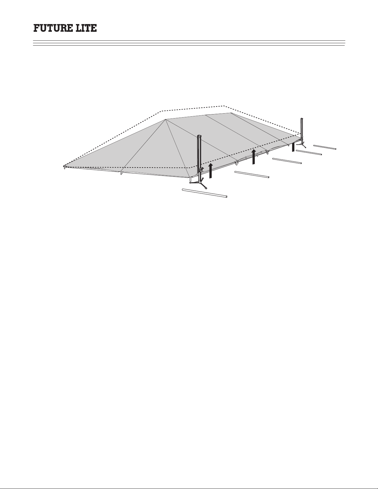
Loosen slings and lower tent jacks. Move all jacks to the opposite side of the tent and place jacks at or near corners or
connection points. Place the slings around the perimeter tubes and operate the winch until the slack is taken up on all the
jacks. Working as a team, raise the tent until the legs can be slipped on. Immediately pin legs and install leg to rafter braces.
Lower jack to set the tent onto its legs. Remove slings and place jacks in the delivery truck.
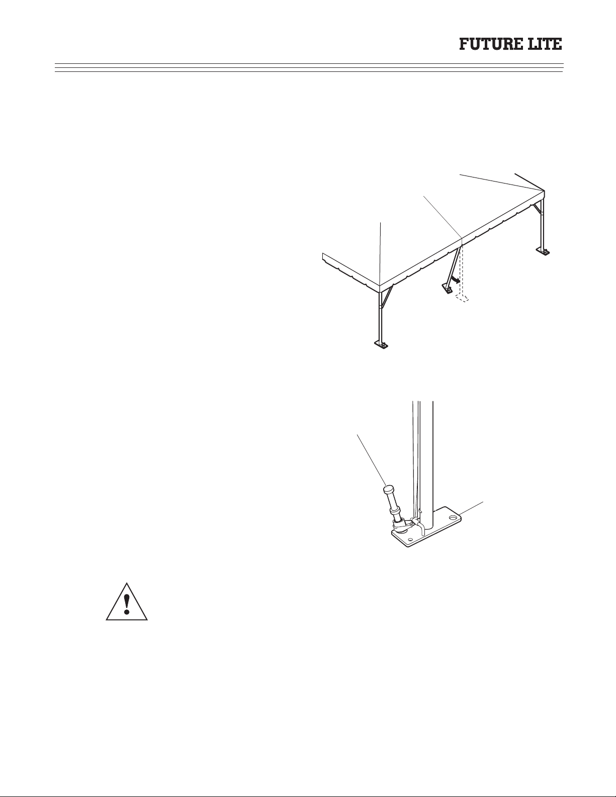
Install the end legs, as shown, starting with the leg inside
of the tent at an angle then, push up and out until the leg
slips onto the connector. Pin leg with 3/8" D-Clasp pin
and install leg brace bar (30 wide only). Finish
connecting all the perimeter buckles. When tensioning
buckle straps, pull until the sidewall rope appears at the
bottom of the perimeter tube. The goal is to have the top
evenly and squarely affixed to the frame. Be sure that all
tie downs and tension straps are in place at the seams and
corners.
The tent must be anchored properly for safe tent
installation. Addditional guys and stakes may be required
depending upon soil and/or wind conditions
Caution! If Keder sidewalls are to be installed, it is necessary that all legs are
straight and in alignment. Legs must be spaced evenly apart for installation of
these sidewalls. A tape measure must be used to assure proper alignment.
BASE PLATE
DOUBLE-HEADED
STAKE
Anchoring Tent
( 10 ) AIFL 2030 1101

Installation Instructions
20 - 30 Wide
Once all the legs have been anchored properly, it is time to
tension the tops using the ratchet straps. Begin the tensioning
process on the eave line (where the end section and mid
section meet) on one side of the tent. Using ratchet, tighten
tops until the Keder is just beginning to show outside of the
Keder rafter. Both Keders should be fairly even, if not, it will
be necessary to loosen and retighten the buckle bands
accordingly to straighten out the top panel. Repeat this
procedure on the opposite side, then at each mid until the top
is tensioned. Next, move to the end leg (middle leg) and
tighten the top until it is snug. The final step will be the
corners. Use caution at this location as the tightening process
is just enough to allow the curtain rope to be pulled down over
the corner. Fold all straps into ratchet cover and Velcro over
to get that fininshed look. Velcro over all corners and eave
flaps to finalize the finished look.
Installed Tent Inspection
1. Staking: Check all stakes for signs of movement.
2. Tensioning: Check all ropes and guy straps for proper tension and make sure the tent top is set for proper drainage.
3. Poles: Check that all poles are properly aligned, securely tied and structurally sound.
4. Sidewalls: Check that they are properly secured as needed.
5. Special Considerations: Make sure that the installation is in compliance with all local building, fire and public safety
codes.
During inclement weather, particularly when the tent is in use, experienced tent personnel
should be present to ensure the security of the equipment and those using it. All parties must
be aware of the limitations for safe occupancy of the tent. The tent renter must retain the right
to declare the tent for unsafe occupancy. Always follow the manufacturer's instructions and
warnings as they take precedence over any conflicting information contained in this manual.
RATCHET STRAPS
BRACE BAR
BASE PLATE
Top Panel Tensioning
( 11 )
AIFL 2030 1101
Installation Instructions
20 - 30 Wide
Top Removal and Folding
To remove the top panels, unbuckle all buckles, disconnect the ratchet straps, check all pins and clips to ensure that they will
not cut or snag the top panels. Always remove the top panels in the same direction as in the installation process.
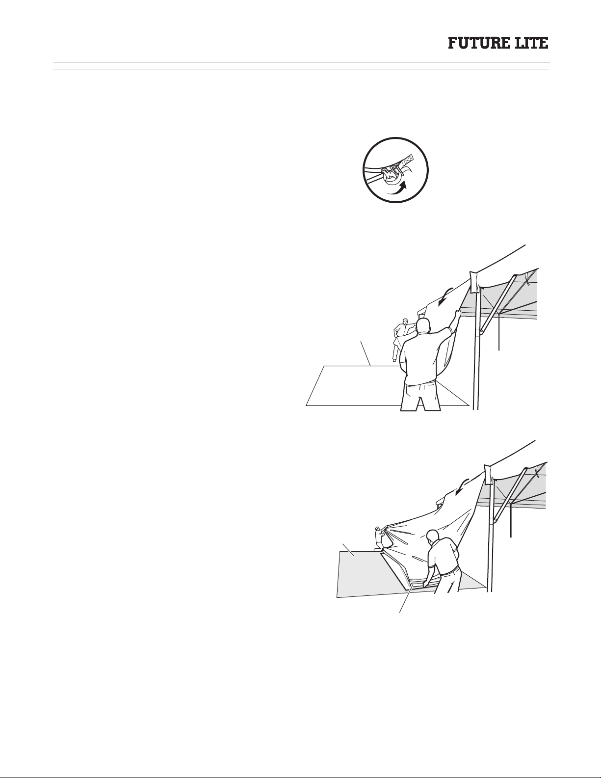
Tip # 1: Always rebuckle (as shown) the buckle straps
on the trailing edge of the top panel. This will greatly
reduce the chance of the buckles getting caught in the
rafters as the tops are being removed.
Tip # 2: Always use ground covers when removing top panels. This will prevent the tops from becoming soiled during the
removal process.
Stand back away from the tent (approximately four feet),
then grab the top panel and pull it towards you as shown
in diagram. Pull gently but firmly on the top panel.
Pull panel sufficiently to allow a three or four foot over-
lap to accordion fold the top. Continue this process until
the top panel is folded. Roll top panel and place into its
storage bag. Continue this process until the remaining
panels have been removed.
Tip # 3: Pulling gently but firmly will lay the top down in a manageable fashion. If it is pulled too hard, it will fall quickly
off the frame and prevent you from getting a nice smooth even fold.
DROP CLOTH
ACCORDION
FOLD TOP
GROUND COVER
( 12 ) AIFL 2030 1101

Installation Instructions
20 - 30 Wide
Lowering Frame
Prepare to lower frame, using jacks, placed about one (1) foot away from the frame. Remove the legs from the center of the
end frame first, then, reverse the installation process to lower the frame to the ground. Lower one side at a time and start
disassembly of the frame starting at one end and working towards the other.
Caution! Safety first when lowering frames. Make sure that all loose objects are out
of the work area. Maintain control of the jacks by keeping a firm grip on the crank
handles.
Tip # 4: Frame disassembly will be faster and easier if you start at one of the corners after removal of the hip pole brace bars
(30 wide only). Remove quick pins from the perimeter poles and hip poles first on the first arch assembly to be taken down.
Remove hip pole lower halves and connectors first, then remove perimeter poles to the first arch assembly. The next step is to
remove the quick pins on the perimeter poles of the next arch assembly, then with sufficient personnel use a step ladder to
remove the ridge rafter from the next arch assembly. Move backward until it clears the crown cluster, then lower the ridge
rafter to the ground. Once off the ladder and it is moved out of the way, pick up the ridge rafter and lower the arch slowly to
the ground. Remove the poles as in the installation process. Repeat this procedure with the remaining sections.
Note: The disassembly procedure is a reversal of the installation process.
( 13 )
AIFL 2030 1101

Installation Instructions
20 - 30 Wide
STEP 1: Install jack handle to winch assembly by
threading handle onto winch assembly.
STEP 2: Install locking bolt, flat washer, spring and
spacer as shown to prevent handle from coming off
winch assembly while lowering.
STEP 3: Install winch assembly to jack upright as
shown by slipping channel on winch mount plate
into function slot. Ensure that support spacers on
winch assembly are facing upward. Locate lower
bolt of winch assembly mounting plate 35 inches
from bottom of jack upright and lock into place with
a 9/16" wrench.
STEP 4: Thread 2" strap through the roller assembly
as shown. Pull strap through support pins on winch
assembly and attach with pin. Be sure pin is inserted
from the gear side. Attach clip pin to lock pin and
strap in place.
STEP 6: Attach jack upright as an assembly to jack
base as shown. Function slot of upright must be
facing outward toward removable leg. Pin with 3/8"
D-clasp pin to lock into place
STEP 5: Remove third leg from its storage location
in the jack base and install with D-clasp pin as
shown.
35-INCHES
RATCHET ASSEMBLY
SLIDES UP FROM
BOTTOM TO 35 INCHES
( 14 ) AIFL 2030 1101
Installation Instructions
20 - 30 Wide
Secure with
D-Clasp Pin
Secure
with D-Clamp
Future Lite
20 x 30
Frame Layout
Future Lite
30 x 45
Frame Layout
L
C
F
B
M
N
O
D-CLASP PIN
AB
C
C
B
A
D
E
F
G
H
I
J
E
EH
G
F
Future Lite
20 ft. & 30 ft.
Arch Assembly
( 15 )
AIFL 2030 1101
K
K
This manual suits for next models
1
Table of contents
Other Toptec Tent manuals


Popular Tent manuals by other brands


Asweets
Asweets Wonder & Wise STAR Assembly instructions

Rocktrail
Rocktrail Z29748 Assembly and Safety Advice

Alice's Garden
Alice's Garden PG3X4ROOF quick start guide

Gutta
Gutta SCOBALIT Pico Top 180 Assembly instructions

PahaQue Wilderness
PahaQue Wilderness TaG Clamshell Tent Setup instructions

P.Lindberg
P.Lindberg 9061126 Original manual