Toptica FemtoFiber pro Series User manual

TOPTICA Photonics AG
Lochhamer Schlag 19
D-82166 Graefelfing/Munich
Tel.: +49 89 85837-0
Fax: +49 89 85837-200
email: info@toptica.com
http://www.toptica.com
(September 2018 Subject to change without notice)
Manual: M-043 Version 07
Copyright 2018 TOPTICA Photonics AG
FemtoFiber®pro
Ultrafast Erbium Fiber Laser System
Manual


FemtoFiber®pro Laser System
Status: 6.9.18
Dear Customer,
Welcome to the TOPTICA community!
We have designed this product to be easy to use and reliable so that you can focus on your work. If you
have questions or need advice on how to integrate it into your setup, please contact us immediately so
we can walk you through the process. We will provide you with quick and competent help through our
service staff and product managers.
You can contact us in the following ways:
- Internet: service.toptica.com. In our support section you can find a list of frequently asked ques-
tions and a service contact form
- Email: service@toptica.com
- Phone: +49-89-85837-150.
Our customers in the USA and Canada may contact TOPTICA Photonics Inc.:
- Phone: +1-585-657-6663
Our customers in Japan may contact TOPTICA Photonics K.K.:
- Phone: +81-42-306-9906
Please have your product -ID and serial number ready when contacting us so we can quickly retrieve all
relevant information.
As we are constantly improving our products, we greatly value all customer feedback. We encourage
you to tell us what you like about our products as well as any suggestions for improvement.
Best regards,
Harald Ellmann
Director Service
TOPTICA Photonics AG


FemtoFiber®pro Laser System
Status: 6.9.18
Contents
1 The FemtoFiber® pro Laser System 5
1.1 Principle of Operation 6
1.2 System Variants 7
1.2.1 Infrared System FemtoFiber® pro IR 7
1.2.2 Infrared System FemtoFiber® pro IRS-II 8
1.2.3 Near-Infrared System FemtoFiber® pro NIR 9
1.2.4 High-Power Yb-doped System FemtoFiber® pro SCYb 11
1.2.5 Super Continuum Infrared System FemtoFiber® pro SCIR 12
1.2.6 Ultra Compressed Pulse System FemtoFiber® pro UCP 13
1.2.7 Tunable Visible System FemtoFiber® pro TVIS 14
1.2.8 Tunable Near Infrared System FemtoFiber® pro TNIR 17
1.3 Options 20
1.3.1 Multi-Arm Laser System 20
1.3.2 Third/Fourth Arm for Seeding Extensions 20
1.3.3 Oscillator Repetition Rate 40 MHz or Customized 21
1.3.4 Variable Laser Repetition Rate 21
1.3.5 Laser Repetition Rate Control 22
1.3.6 TNIR Secondary Output for UCP and TVIS 23
2 Safety Instructions and Warnings 24
2.1 General Safety Terms 24
2.2 Safety Labels 26
2.2.1 Protective Housing 26
2.2.2 Laser Beam 27
2.2.3 Apertures 28
2.2.4 CFR Compliance 28
2.3 Identification of Manufacturer 29
2.3.1 FemtoFiber® pro Control Unit 29
2.3.2 FemtoFiber® pro Laser Head 29
2.4 Identification Labels 29
2.5 Safety Features of the FemtoFiber® pro Laser System 30
2.5.1 External Interlock 30
2.5.2 Laser Beam Shutter 31
2.5.3 Fuses 32
3 Installation 33
3.1 Inspection after Delivery 33
3.2 Installation Instructions FemtoFiber® pro Laser Head 36
4Operation 37
4.1 Operator Controls FemtoFiber® pro Laser Head 37
4.1.1 Description of Operator Controls FemtoFiber® pro Laser Head 38
4.2 Operator Controls FemtoFiber® pro Control Unit 39
4.2.1 Description of Operator Controls FemtoFiber® pro Control Unit 40
4.3 Connection of the FemtoFiber® pro Laser System 41
4.3.1 FemtoFiber® pro Multi-Arm Laser Systems 41
4.3.2 Additional Connections FemtoFiber® pro with VAR and LRC Option 42
4.4 Power Up of FemtoFiber® pro Systems 43
4.5 Power Down 43

FemtoFiber®pro Laser System
Status: 6.9.18
5 Computer Control of the FemtoFiber® pro Laser System 44
5.1 System Requirements 44
5.2 USB Connection 44
5.2.1 Installation of FTDI CDM Drivers for USB Connection 44
5.3 Installation of FemtoFiber® pro GUI-Software 47
5.4 Start of FemtoFiber® pro GUI-Software 51
5.5 Operation of FemtoFiber® pro GUI-Software 52
5.5.1 General 52
5.5.2 Connection Tab 53
5.5.3 Laser Control Tab 54
5.5.4 Laser Control Tab Standard System UCP and TVIS Variant 55
5.5.5 Laser Control Tab Multi-Arm Laser System 56
5.5.6 Info Tab 57
5.5.7 Console Tab 58
5.6 Ethernet Connection 59
5.6.1 Installation of the Ethernet Connection 59
5.7 Web Frontend 60
5.7.1 Operation 61
5.7.2 Python Command List 61
5.7.3 Console 62
5.7.4 System Properties 63
5.7.5 Debug Logfile 63
5.7.6 Service Logfile 63
5.7.7 Data Transfer 63
5.7.8 Firmware Update 64
6 Appendix 65
6.1 Specifications of FemtoFiber® pro Laser Systems 65
6.2 FemtoFiber® pro with VAR Option 65
6.2.1 Installation 65
6.2.2 Additional Connections 65
6.3 FemtoFiber® pro with LRC Option 66
6.3.1 Installation 66
6.3.2 Additional Connections 66
6.3.3 LRC Plug in Modules 67
6.3.4 LRC Software and Drivers 72
6.3.5 Quick Start 76
6.3.6 Switch-Off Procedure 76
6.3.7 Software and Driver Installation with Windows 7 77
6.4 Computer Control via RS 232 Connection 79
6.5 Firmware Update 80
6.6 Troubleshooting 82
6.6.1 Selftest, System Status and Error Logging 82
6.7 General Information on the Python Programming Language 83
6.7.1 Properties 83
6.7.2 Commands 84
6.7.3 Error Messages 85

Status: 6.9.18
6.8 Userlevels 86
6.8.1 General 86
6.8.2 Changing the UserLevel 86
6.9 FemtoFiber® pro Operation via Software Commands 87
6.9.1 Basic Operation 87
6.9.2 Tuning the internal Pulse Compressor 87
6.9.3 Tuning the internal SF 10 Compressor (only UCP and TVIS) 89
6.9.4 Reducing the Power Level 90
6.9.5 System Status 90
6.9.6 Troubleshooting 91
6.9.7 Error Log 92
6.9.8 Full Command Set 93
6.10 Declaration of CE Conformity FemtoFiber® pro 94
6.11 Declaration of CE Conformity FemtoFiber® pro SCYb 95
6.12 FemtoFiber® pro Laser Head Main Dimensions (IR/NIR/SCIR) 96
6.13 FemtoFiber® pro Laser Head Main Dimensions (IRS-II/SCYb) 97
6.14 FemtoFiber® pro Laser Head Main Dimensions (UCP/TNIR/TVIS) 98
6.15 FemtoFiber® pro Laser Head Mounting Options (IR/IRS-II/NIR/SCYb/SCIR) 99
6.16 FemtoFiber® pro Laser Head Mounting Options (UCP/TVIS/TNIR) 100
6.17 License and Copyright Information associated with Third Party Software 101
6.18 EU Legislation for Electrical and Electronic Equipment (EEE) 101
7 Guarantee and Service 102

FemtoFiber®pro Laser System
Status: 6.9.18

1. The FemtoFiber® pro Laser System
Page 5
Status: 6.9.18
1 The FemtoFiber®pro Laser System
Mode-locked femtosecond lasers have nowadays found their way into a wide variety of both scientific
and industrial applications. With the FemtoFiber®pro Laser System, TOPTICA Photonics AG merges the per-
formance of traditional Ti:Sapphire oscillators with the advantages of an all-fiber laser source. Combining
pump sources, a SAM (saturable absorber mirror) mode-locked ring oscillator, an all-fiber core-pumped
amplifier and optical pulse compression into a single compact housing, the FemtoFiber®pro Laser Sys-
tem offers a maximum of user-convenience and flexibility without compromising performance.
Ultrafast spectroscopy with femtosecond laser pulses continues to be a flourishing field of scientific
interest. To date, a multitude of experiments has been carried out with free-space Ti:Sapphire sources.
Although these systems offer high output power and good pulse characteristics, their operation is often
cumbersome for the user. Mode-locking is typically accomplished via nonlinear self-focussing, requiring
highly precise alignment and daily readjustment of the laser cavity. Moreover, the need for a high-power
pump source in the green spectral range has led to considerable system costs and increased space
requirements.
The release of TOPTICA’s mode-locked Er:fiber laser system FemtoFiber®pro marked a significant step
forward towards the availability of cutting-edge femtosecond technology as a standard tool in any
research environment. Based on direct pumping from fiber-pigtailed laser diodes and fiber integrated,
reliable telecom components, the FemtoFiber®pro Laser System delivers more than 350 mW of linearly
polarized and highly stable output power in sub-100 fs pulses in a user-friendly and compact design. Due
to its superior performance, high stability, great flexibility, excellent cost-efficiency and advanced user-
friendliness, the new FemtoFiber®pro Laser System can be the ideal solution to your research in fields as
diverse as ultrafast spectroscopy, optical frequency metrology, THz spectroscopy, confocal microscopy,
material sciences and many more.
Figure 1 The FemtoFiber®pro laser system

FemtoFiber®pro Laser System
Page 6
Status: 6.9.18
1.1 Principle of Operation
Figure 2 Schematic setup of the FemtoFiber®pro laser system
The FemtoFiber® pro Laser System illustrated in Figure 2 is based on state-of-the-art telecom components.
A core-pumped fiber, doped with Erbium ions, acts as the active laser medium. A so called saturable
absorber mirror (SAM) inside the ring cavity (1) in Figure 2 favors mode-locked operation over continuous
wave laser activity by exploiting the effect of picking and amplifying only pulses with a certain ampli-
tude. As a consequence, the mode locked ring oscillator generates well-defined light pulses at a center
wavelength of 1560 nm with a repetition rate of 80 MHz (standard, other rep. rates upon request).
With the high gain available from Er:fibers, the optical power extracted from the oscillator is used for
seeding optical amplifiers. Every laser system contains an internal amplifier, but also has one (or more)
FC/APC ports for seeding external amplifiers, e.g. for multiple beam experiments needing synchronized
pulses, such as pump-probe experiments.
The pulse duration is controlled by a variable dispersion control unit, formed by a motorized prism
compressor (2). The light pulses typically exhibit a duration of less than 100 fs (or longer if desired) with an
average power of more than 350 mW.

1. The FemtoFiber® pro Laser System
Page 7
Status: 6.9.18
1.2 System Variants
1.2.1 Infrared System FemtoFiber®pro IR
The basic system of the FemtoFiber®pro series, the FemtoFiber®pro IR, is a compact system comprising
oscillator, amplifier and prism compressor in a single box. The unit delivers a collimated free-beam with
more than 350 mW at 1560 nm fundamental wavelength.
Figure 3 FemtoFiber®pro IR laser beam
The basic properties of a FemtoFiber®pro IR are shown in the following typical measurements.
Figure 4 Typical pulse characteristics and emission spectrum of FemtoFiber®pro IR
The pulses show a width of less than 100 fs using the auto correlation measurement method (Figure 4 left).
The laser also shows a typ. 80 nm wide spectrum centered at the fundamental wavelength 1560 nm (Fig-
ure 4 right).

FemtoFiber®pro Laser System
Page 8
Status: 6.9.18
1.2.2 Infrared System FemtoFiber®pro IRS-II
The FemtoFiber®pro IRS-II is a short-pulse version of TOPTICA´s FemtoFiber®pro series. It comprises a very
robust master-oscillator with power amplifier in one single box. It is built as an all-fiber laser system with no
free space optics. By use of a special non-linear fiber, shortest pulses at the fundamental wavelength of
Er-doped fiber lasers are generated.
Figure 5 FemtoFiber®pro IRS-II laser beam
The basic properties of a FemtoFiber®pro IRS-II are shown in the following typical measurements.
Figure 6 Typical Pulse characteristics and emission spectrum of FemtoFiber®pro IRS-II

1. The FemtoFiber® pro Laser System
Page 9
Status: 6.9.18
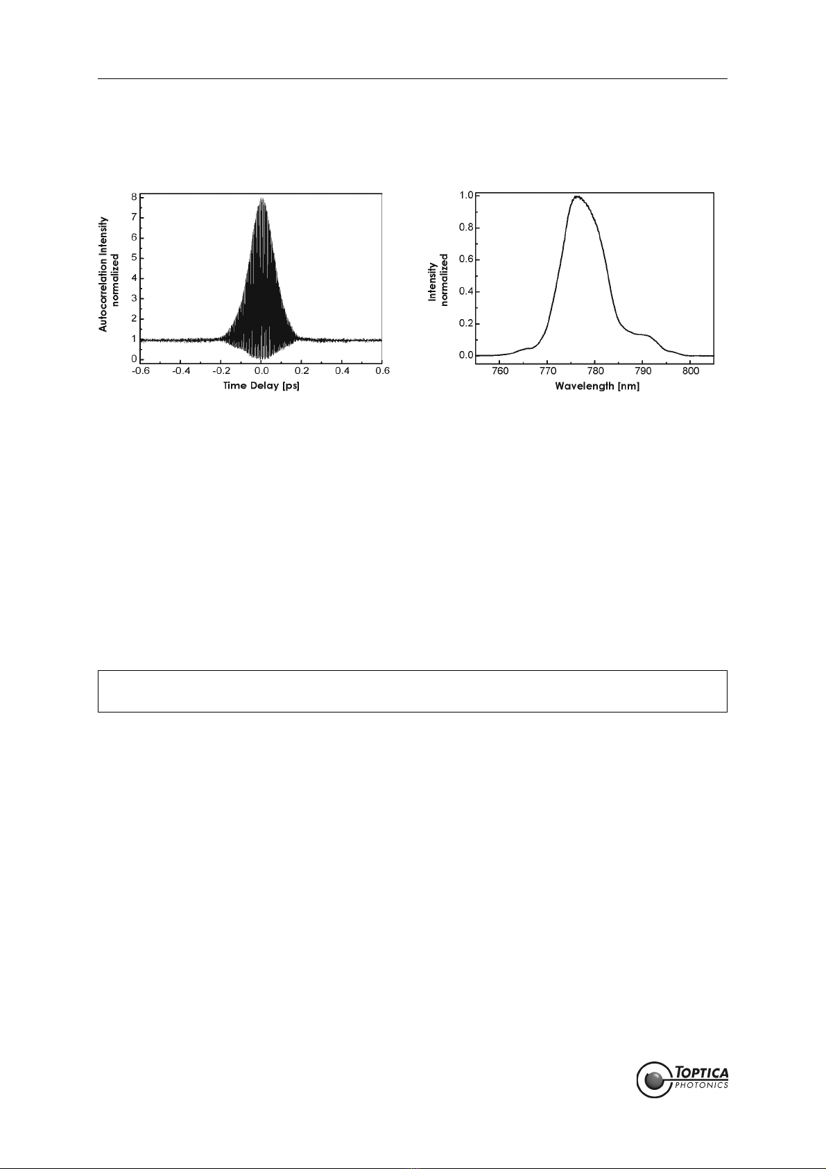
1.2.3 Near-Infrared System FemtoFiber®pro NIR
In addition to the features of the FemtoFiber®pro IR, the FemtoFiber®pro NIR includes an additional exit
aperture with a single-pass second-harmonic generation (SHG) using a periodically poled Li:NbO3(PPLN)
crystal. The FemtoFiber®pro NIR therefore provides two switchable exit ports for the fundamental wave-
length 1560 nm (> 350 mW) and the second harmonic of 780 nm (> 140 mW).
Figure 7 FemtoFiber®pro NIR laser beams and operation of 1560/780-switch (right)
Figure 8 FemtoFiber®pro NIR internal setup
NOTE ! Switching between 780 and 1560 nm is done by a mechanical switch, which is inserting or
removing a mirror (see Figure 8) into/from the beam path and either reflects the funda-
mental 1560 nm to the secondary aperture or passes it towards the SHG unit and to the
primary aperture. Both wavelengths simultaneously are not available (with standard/
default configuration)..
For laser safety reasons switch OFF the laser emission or make sure the shutters are closed
before operating the 1560/780-Switch !
FemtoFiber®pro Laser System
Page 10
Status: 6.9.18
The typical characteristics of the fundamental wavelength are the same as shown for the basic system
FemtoFiber®pro IR (see Figure 4). The frequency-doubled characteristics are shown in the following typi-
cal measurements.
Figure 9 Typical pulse characteristics and emission spectrum of FemtoFiber®pro NIR (SHG output)
The auto correlation shows a smooth shape with a pulse width of less than 100 fs, similar to the measure-
ment at the fundamental wavelength (Figure 9 left). The spectral width is typically 10 - 15 nm wide (Figure
9 right).
The FemtoFiber®pro NIR variant is equipped with an auto optimize feature which constantly adjusts
the average power to maximum when active. For details of the operation please refer to section 5.5.3.
1.2.3.1 1 ps Option for FemtoFiber®pro NIR
This option uses a different crystal and generates typ. 1 ps long, rectangular shaped pulses. The pulses
are nearly transform-limited (spectral width in few nm range). The output power of such a system typi-
cally reaches 100 mW.
NOTE ! The 1 ps option replaces the regular SHG crystal, which is not available anymore when this
option is added.

1. The FemtoFiber® pro Laser System
Page 11
Status: 6.9.18
1.2.4 High-Power Yb-doped System FemtoFiber®pro SCYb
The FemtoFiber®pro SCYb is an all-fiber high-power laser system at 1030 nm emission wavelength, provid-
ing more than 500 mW on average and pulses shorter than 100 fs. It is based on a very stable SAM mode-
locked Er-doped oscillator running at 1560 nm which gets frequency shifted into the 1030 nm range by
use of a nonlinear fiber. The output power is then amplified by Yb-doped amplifiers to levels of up to typ-
ically 600 mW. The unit also includes a small grating compressor unit to achieve transform-limited output
pulses of typ. 90-100 fs, with more than 70 % power in the main peak.
Figure 10 FemtoFiber®pro SCYb laser beam
Figure 11 Typical pulse characteristics and emission spectrum of FemtoFiber®pro SCYb

FemtoFiber®pro Laser System
Page 12
Status: 6.9.18
1.2.5 Super Continuum Infrared System FemtoFiber®pro SCIR
Alternately to the second-harmonic stage, the FemtoFiber®pro SCIR provides a supercontinuum genera-
tion by using a highly nonlinear fiber (HLNF). This fiber generates a widened spectrum of 980 to 2200 nm,
which is available at the primary exit aperture.
Figure 12 FemtoFiber®pro SCIR laser beam
Figure 13 FemtoFiber®pro SCIR continuum in dependence of prism position
By adjusting the motorized prism compressor (see section 5.5.3), the continuum can be altered to
achieve a certain light intensity at a certain wavelength. This is illustrated in Figure 13.

1. The FemtoFiber® pro Laser System
Page 13
Status: 6.9.18
1.2.6 Ultra Compressed Pulse System FemtoFiber®pro UCP
The FemtoFiber®pro UCP (Ultra Compressed Pulse) is the first model of the extended versions of TOPTICA's
FemtoFiber®pro series. It comprises a very rugged master-oscillator with a power amplifier in a very com-
pact design. Two motorized prism compressors are integrated: One for tuning the wavelength by adjust-
ing the frequency-domain supercontinuum characteristics and a second for compressing and optimizing
the time-domain laser pulse shape.
Figure 14 FemtoFiber®pro UCP laser beam
Figure 15 Typical Pulse characteristics and emission spectrum of FemtoFiber®pro UCP

FemtoFiber®pro Laser System
Page 14
Status: 6.9.18
1.2.7 Tunable Visible System FemtoFiber®pro TVIS
The FemtoFiber®pro TVIS (Tunable VISible) is a further extension of the previously described UCP system.
The compressed continuum is getting frequency-doubled into the visible light region by a following non-
linear crystal. The crystal unit allows a continuous manual fine-tuning of the wavelength by a fine thread
screw from 488 to 640 nm.
Figure 16 FemtoFiber®pro TVIS laser beam

1. The FemtoFiber® pro Laser System
Page 15
Status: 6.9.18
Figure 17 Typical pulse characteristics, emission spectra and power distribution of the tunable FemtoFi-
ber®pro TVIS system

FemtoFiber®pro Laser System
Page 16
Status: 6.9.18
1.2.7.1 Options
Extended Tuning Range Option
The FemtoFiber®pro TVIS can be equipped with different crystals to extend the tuning range to 488 -
700 nm. In case this option is ordered, the standard crystal is exchanged to a two-crystal design, where
the first crystal works from 480 - 540 nm, and the second from 520 - 700 nm.
Short Pulse Option
Instead of the typical 300 .. 600 fs pulse width as shown in Figure 17, lower graph, right y-axis, the system
can be equipped with special focusing optics in order to allow shorter pulses in the range of 100 .. 150 fs
instead.
NOTE ! The Extended Tuning Range option consists of two crystal mounts carrying two different
crystals (crystal 1: 488 .. 540 nm, crystal 2: 520 .. 700 nm). The procedure how to change
the crystal mounts is shown in the installation training.
The Extended Tuning Range option replaces the regular SHG crystal, which is not available
anymore when this option is added.
Continuous tuning from 488 to 700 nm is not possible with the Extended Tuning Range
option, as the crystal needs to be exchanged manually.
NOTE ! Power levels above 640 nm are typically in the range of 0.5 - 1 mW. It is not possible to
increase the output power in this range, since the original supercontinuum does not have
enough power in that range.
This manual suits for next models
8
Table of contents
Other Toptica Measuring Instrument manuals


