Toptica FemtoFiber smart User manual

TOPTICA Photonics AG
Lochhamer Schlag 19
D-82166 Graefelfing/Munich
Tel.: +49 89 85837-0
Fax: +49 89 85837-200
email: info@toptica.com
http://www.toptica.com
(September 2018 Subject to change without notice)
Manual: M-056 Version 08
Copyright 2018 TOPTICA Photonics AG
FemtoFiber smart
Ultrafast
Fiber Laser
Manual

FemtoFiber smart Manual
Status: 6.9.18
Dear Customer,
Welcome to the TOPTICA community!
We have designed this product to be easy to use and reliable so that you can focus on your work. If you
have questions or need advice on how to integrate it into your setup, please contact us immediately so
we can walk you through the process. We will provide you with quick and competent help through our
service staff and product managers.
You can contact us in the following ways:
- Internet: service.toptica.com. In our support section you can find a list of frequently asked ques-
tions and a service contact form
- Email: service@toptica.com
- Phone: +49-89-85837-150
Our customers in the USA and Canada may contact TOPTICA Photonics Inc.:
- Phone: +1-585-657-6663
Our customers in Japan may contact TOPTICA Photonics K.K.:
- Phone: +81-42-306-9906
Please have your product ID and serial number ready when contacting us-so we can quickly retrieve all
relevant information.
As we are constantly improving our products, we greatly value all customer feedback. We encourage
you to tell us what you like about our products as well as any suggestions for improvement.
Best regards,
Harald Ellmann
Director Service
TOPTICA Photonics AG

FemtoFiber smart Manual
Status: 6.9.18
Contents
1 General Description of the FemtoFiber smart System 3
1.1 Ytterbium Fiber Lasers 3
1.2 Erbium Fiber Lasers 4
1.3 FemtoFiber smart Switch Box (Optional) 5
1.3.1 USB-Control 5
2 Safety Instructions and Warnings 6
2.1 General Safety Terms 6
2.2 Safety Labels 8
2.2.1 Laser Beam 8
2.2.2 Apertures 8
2.2.3 CFR Compliance 9
2.3 Identification of Manufacturer 9
2.4 Safety Features 10
2.4.1 External Interlock 10
2.4.2 Shutter (Free Beam Version) 10
2.4.3 Protection Cap on Fiber Pigtail or FC/APC Connector 10
3 Installation 11
3.1 Package Contents 11
3.2 Installation Instructions 12
4Operation 13
4.1 Operator Controls FemtoFiber smart Laser 13
4.2 Operator Controls FemtoFiber smart Switch Box 15
4.3 FemtoFiber smart System Quickstart 18
4.3.1 OEM Integrated Environment 18
4.3.2 Manual Operation via Switch Box 19
4.3.3 FemtoFiber smart Operation via Software Commands 20
4.3.4 FemtoFiber smart Operation with Graphical User Interface 23
4.3.5 System Requirements 23
5 TOPAS FemtoFiber smart Control Software 27
5.1 Upper and Lower Screen Section 27
5.1.1 Header 27
5.1.2 Footer 27
5.1.3 Menu 28
5.1.4 Help 31
5.2 Control Section 32
5.2.1 System Info Tab 33
5.2.2 Micro Mover Tab (only FYb Systems) 34

Status: 6.9.18
6Appendix 35
6.1 Specifications 35
6.2 Pin Assignment D-Sub 9 Input/Output Connector 35
6.3 Operation without Switch Box (Control via TTL/Analog Pins) 36
6.4 Pin Assignment of Laser On Input Connector (Switch Box) 37
6.5 Pin Assignment of Power Supply Connector (Switch Box) 37
6.6 Firmware Update 38
6.7 USB Connection (Installation of FTDI CDM Drivers) 39
6.8 Precautions for Non-Condensing Operation Conditions 41
6.9 Declaration of CE Conformity 42
6.10 Main Dimensions of the FemtoFiber smart System Versions 43
6.10.1 FemtoFErb Free Beam 43
6.10.2 FemtoFErb with Fiber Pigtail 44
6.10.3 FemtoFErb with FC/APC Fiber Connector 45
6.10.4 Femto/PicoFYb with Fiber Pigtail 46
6.11 License and Copyright Information associated with Third Party Software 47
6.12 EU Legislation for Electrical and Electronic Equipment (EEE) 47
7 Guarantee and Service 48

FemtoFiber smart Manual
Page 3
Status: 6.9.18
1 General Description of the FemtoFiber smart System
Ultrafast fiber lasers provide an ideal combination of system parameters: Small form factor at low cost,
but on the other hand reliable and having brilliant laser performance. Various bulky and cost-consuming
solid-state laser concepts are therefore getting more and more replaced by robust and reliable turnkey
fiber lasers.
TOPTICA´s FemtoFiber smart lasers are the most compact and cost-effective laser sources for Terahertz
generation. Other applications benefiting from the FemtoFiber smart laser solutions are e.g. metrology
systems, light sources for microscopy, ophthalmology or medical surgery/ examination.
The FemtoFiber smart laser systems are based on rare earth doped fibers and saturable absorber mir-
ror (SAM) mode-locking technology. Generally, the fiber technology ensures a very compact design and
highest robustness against vibration or mechanical shocks. The use of mass produced fiber components
with the proof of Telcordia standards provides an unique cost-benefit ratio. The passive SAM device
ensures self-starting and reliable mode-locking.
Key Features for all systems of the FemtoFiber smart family:
•Turnkey
•Compact
• State of the art FemtoFiber technology: robust and reliable all- fiber setup
• Fiber coupled output
• All necessary control electronics inside
• Telcordia proved components
The FemtoFiber smart lasers are plug & play systems for both OEM integrators and single unit customers.
They provide an electrical interface for remote control and only need 12 ± 2 V DC filtered supply input for
all internal electronics. For single system users the supplied Switch Box provides all switches, supply and
status lines to run a FemtoFiber smart as a stand-alone system without integration environment.
Alternatively, FemtoFiber smart laser heads can also be controlled via an USB-interface.
1.1 Ytterbium Fiber Lasers
PicoFYb 1030/1064
The PicoFYb laser systems are fiber-based picosecond oscillators for seeding industrial laser systems, e.g.
for micro-machining. The PicoFYb laser pulses with excellent amplitude and frequency jitter parameters
are amplified to typical multi-Watt levels in the MOPA (master oscillator, power amplifier) laser or regen-
erative amplifier systems of our customers. Typical amplifiers are slab, rod and disc lasers operating in the
1 µm wavelength regions.
FemtoFYb 1030
The FemtoFYb laser systems are fiber-based sub-picosecond to femtosecond oscillators for seeding
industrial laser systems, e.g. for micro-machining. The FemtoFYb laser pulses with excellent amplitude and
frequency jitter parameters are amplified to typical multi-Watt levels in the MOPA (master oscillator,
power amplifier) laser or regenerative amplifier systems of our customers. Typical amplifiers are slab, rod
and disc lasers operating in the 1 µm wavelength regions.
NOTE ! Please refer to the website www.toptica.com for detailed specifications of the FemtoFiber
smart.
For individual laser system specifications, please refer to the Production and Quality Con-
trol Data Sheet.

FemtoFiber smart Manual 1. General Description of the FemtoFiber smart System
Page 4
Status: 6.9.18
1.2 Erbium Fiber Lasers
FemtoFErb 1560
The FemtoFErb 1560 is a very robust all fiber-based femtosecond laser system with excellent amplitude
and frequency jitter parameters. Applications benefiting from the most stable, compact and cost-effec-
tive FemtoFErb 1560 are e.g. Terahertz or metrology systems, light sources for microscopy, ophthalmology
or medical surgery/examination.
FemtoFErb 1560 FD6.5
The FemtoFErb 1560 FD6.5 is the fiber delivery version of the FemtoFErb 1560 providing a 6.5 m external
SM PM 1560 fiber and transform-limited pulses at the fiber end. This allows replacing complex beam deliv-
ery setups by flexible and convenient fiber solutions. Applications benefiting from the most stable, com-
pact and cost-effective FemtoFErb FD6.5 are e.g. Time-Domain Terahertz, medical applications like
endoscopy or metrology systems.
FemtoFErb 1560 and FemtoFErb 1560 FD6.5 with THz Option
This option includes a special technology called QuTE (Qu-Switch Termination) allowing the laser to be
connected permanently and directly to the THz antennas. This option prevents possible Q-switch pulses
to reach the antennas, which may occur at the laser start-up procedure.
FemtoFErb 780
The FemtoFErb 780 is a very compact all fiber-based femtosecond laser system with integrated miniatur-
ized second-harmonic generation unit. It unites both supply electronics and laser unit in one box, being
thus one of the smallest fiber laser units on the market. The system only needs 12 ± 2 V DC filtered power
supply and comprises a free-beam output with mechanical shutter.
FemtoFErb 1950
The FemtoFErb 1950 laser is a very robust all fiber-based femtosecond laser system with excellent ampli-
tude and frequency jitter parameters. A frequency shifted solitonic pulse is generated by nonlinear
effects. The unit is used for seeding Thulium doped amplifiers and also for other purposes in the 2 µm
wavelength range

FemtoFiber smart Manual 1. General Description of the FemtoFiber smart System
Page 5
Status: 6.9.18
1.3 FemtoFiber smart Switch Box (Optional)
The FemtoFiber smart Switch Box is a small tool which provides all switches as well as supply and status
lines necessary to run a FemtoFiber smart laser as a stand-alone system without integration environment
and therefore is recommended especially for single-system users.
Figure 1 FemtoFiber smart Switch Box
1.3.1 USB-Control
All FemtoFiber smart laser heads are equipped with a serial USB interface for remote control of the laser
and to integrate it into software environments.
In order to establish an USB connection a USB cable (max. 2 meters length) and a suitable computer
with a free USB 2.0 port are needed. For further details of the USB-Control please refer to section 4.3.3.
NOTE ! All FemtoFiber smart lasers are principally designed for OEM integration.
For stand-alone operation of a FemtoFiber smart: In order to achieve full accordance with
general and nation-specific laser safety regulations (IEC 60825, CDRH, etc.), it is necessary
to supply a FemtoFiber smart laser with a Switch Box at all time !
NOTE ! A FemtoFiber smart laser system operated without Switch Box, but instead with 12 V direct
power supply and USB remote control, is officially not approved by TOPTICA for stand-alone
applications. This combination would circumvent the general laser safety regulations (no
interlock mechanism, no lockable power key-switch etc.). TOPTICA waives all liabilities for
such setups.
This note is not valid for OEM integrators.
FemtoFiber smart Manual 2. Safety Instructions and Warnings
Page 6
Status: 6.9.18
2 Safety Instructions and Warnings
The following Safety Instructions and Warnings should be read and complied with during operation or
maintenance of FemtoFiber smart. Failure to do so could result in damage to FemtoFiber smart or/and
personal injury or death.
2.1 General Safety Terms
FemtoFiber smart is manufactured according to the Laser Safety Standard EN 60825-1:2014 and complies
with US law 21 CFR §1040.10 and §1040.11.
The following safety terms are used in this manual:
The DANGER ! heading in this manual explains hazards that could result in personal injury or death.
The CAUTION ! heading in this manual explains hazards that could damage the instrument.
In addition, a NOTE ! heading gives information to the user that may be beneficial when using the
device.
DANGER ! Before operating the FemtoFiber smart please read this manual carefully to prevent personal
CAUTION ! injury and damage to the device. The following safety instructions must be followed at all
times.
DANGER ! Possibility of electrical shock ! Wherever this symbol is attached, the possibility of an
CAUTION ! electrical shock may appear. Use only equipment and accessories supplied
by TOPTICA.
Caution ! Wherever this symbol is attached read and understand the manual before
operating the device. The manual must be consulted in order to find out the nature
of the potential HAZARDS and any actions which have to be taken to avoid them.
DANGER ! OEM use of the FemtoFiber smart Laser Source (integration into an end device, operation
CAUTION ! without Switch Box): The operator or designer of the end device is responsible for integration
of a key switch and an interlock circuit to the 12 ± 2 V DC Supply as well as to install redun-
dant laser emission warning lamps, a shutter and to apply the according laser safety labeling
according to the Laser Safety Standard EN 60825-1:2014.
DANGER ! The Laser Driver Electronics (Switch Box) and the Laser Head are both equipped with LEDs
CAUTION ! that indicate laser emission. (Please refer to sections 4.1 and 4.2 in this manual for detailed
information).
Be aware of laser emission when at least one of these LEDs lights up.

FemtoFiber smart Manual 2. Safety Instructions and Warnings
Page 7
Status: 6.9.18
DANGER ! During installation, maintenance and service, all persons in the room must wear appropriate
laser safety goggles while the laser is in operation. The recommended protection stage is
dependent on the laser system.
Use appropriate eyewear and other protective means in order to keep radiation exposure
below the maximum permissible levels allowed by applicable regulations (examples: OSHA
limits in the US, BGV B2, BGI5092, TROS Laserstrahlung in Germany).
To determine the protection level of the laser safety goggles required for e.g. FemtoFErb 780
laser system, please refer to the following example: FemtoFErb 780 with collimated beam,
beam diameter 1.6 mm, wavelength = 780 nm, repetition rate 100 MHz, laser power up to 60-
70 mW generates a peak power density of HM~ 0.3 mJ/m² (approximately). From Table 3 in
BGI5092 this leads to a required protection level of 780 D LB 4 + M LB 1 for your eyewear.
DANGER ! Laser safety goggles selected for adjustment purposes do not protect against an intention-
ally focused direct beam which will increase the optical power densities by a few orders of
magnitude.
DANGER ! Regular functional checks and performance inspections at the supplier are recommended
for all laser safety goggles.
DANGER ! Do not position the equipment so that it is difficult to operate the disconnecting device.
DANGER ! Use of controls or adjustments or performance of procedures other than those specified
herein may result in hazardous radiation exposure.
DANGER ! If the equipment is used in a manner not specified by the manufacturer, the protection pro-
vided by the equipment may be impaired.
DANGER ! The FemtoFiber smart uses very powerful lasers (up to class 3B). Therefore, it is imperative to
take great care and observe the statutory warning labels on the unit.
DANGER ! Do not open the device at any time, FemtoFiber smart is a hands-off laser system. Reflections
of the laser beam may cause serious injury to your eyes. Internal tuning as well as the replac-
ing of components may only be carried out by TOPTICA. Under certain circumstances there
may be dangerous voltages, even if the device is disconnected from the mains supply.
DANGER ! Do not look into the beam from the Laser Output (depending on the version: free beam, FC/
APC connector(s) on front panel or FC/APC connector at the fiber pigtail) as the output can
exceed the limits for class 1 specified by US laws 21 CFR 1040.10 and 2 CFR 1040.11 and the
Laser Safety Standard EN 60825-1:2014. Take precautions to eliminate exposure to a direct or
reflected beam.
DANGER ! FemtoFiber smart may not be operated in surroundings of flammable gases or fumes.
CAUTION ! Special precautions are necessary if FemtoFiber smart is to be operated in surroundings of
high electro-magnetic radiation such as close to a plasma discharge. Please refer to TOPTICA
for technical support.
CAUTION ! Since the FemtoFiber smart has power levels which may already destroy optical fibers, please
pay special attention to a clean fiber facet at the output fiber connector. We also recom-
mend to always switch-off the laser emission before the fiber connector is opened/closed!
CAUTION ! FemtoFErb 1560 standard version: While starting the laser it may occur that higher level pulses
are sent out by the laser. This transient phenomenon is due to the fact that the amplifier of
the system starts simultaneously with the oscillator. We therefore recommend blocking the
output beam at the moment when the laser is switched on, or adding the THz option.

FemtoFiber smart Manual 2. Safety Instructions and Warnings
Page 8
Status: 6.9.18
2.2 Safety Labels
2.2.1 Laser Beam
FemtoFiber smart emits invisible pulsed laser radiation of up to 170 mW power. It is classified as Class 3B
product.
The following labels are affixed to the outer side of the FemtoFiber smart laser protective housing accord-
ing to EN 60825-1:2014:
Size: 52 mm x 26 mm
Color: yellow/black
Location: Outer side of the FemtoFiber smart laser protective housing
2.2.2 Apertures
During operation, depending on the individual system, the laser beam is emitted at the laser beam aper-
ture(s), either free beam, from the FC/APC fiber connector at the front panel or from the fiber pigtail.
The following labels are affixed to the outer side of the FemtoFiber smart laser protective housing next to
the laser beam aperture(s) according to EN 60825-1:2014:
Size: 26 mm x 13 mm Size: 15 mm x 15 mm
Color: Yellow/black Color: Yellow/black
Location: Besides laser beam aperture(s) Location: FemtoFiber smart laser protective
housing
DANGER ! FemtoFiber smart emits invisible pulsed laser radiation of up to 170 mW power (Class 3 B
laser product). Avoid exposing eyes and skin to the laser beam, including any laser stray
light !
DANGER ! FemtoFiber smart emits invisible pulsed laser radiation of up to 170 mW power (Class 3B
laser product). Avoid exposing eyes and skin to the laser beam, including any laser stray
light !
FemtoFiber smart Manual 2. Safety Instructions and Warnings
Page 9
Status: 6.9.18
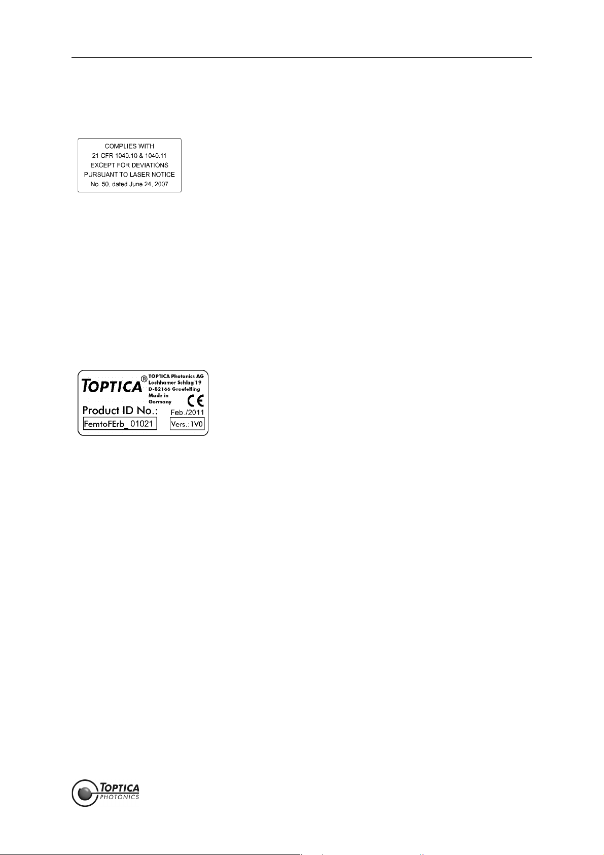
2.2.3 CFR Compliance
Compliance with US laws 21 CFR §1040.10 and §1040.11 is declared by the following label:
Size: 38 mm x 19 mm
Color: silver/black
Location: FemtoFiber smart Laser Head
housing
2.3 Identification of Manufacturer
Manufacturer (name and address), production date, FemtoFiber smart model, serial number, article
number and compliance with CE standards are noted on the identification label:
Size: 38 mm x 19 mm
Color: Silver/black
Location: Outer side of the FemtoFiber smart laser protective housing
FemtoFiber smart Manual 2. Safety Instructions and Warnings
Page 10
Status: 6.9.18
2.4 Safety Features
2.4.1 External Interlock
An interlock circuit to connect e.g. a door switch can be set up by using the Interlock Connector on the
Switch Box (for location please refer to Section 4.2). For first operation, a bridged interlock plug is supplied
to close the interlock circuit. For safety reasons the installation of an external interlock circuit is strongly
recommended.
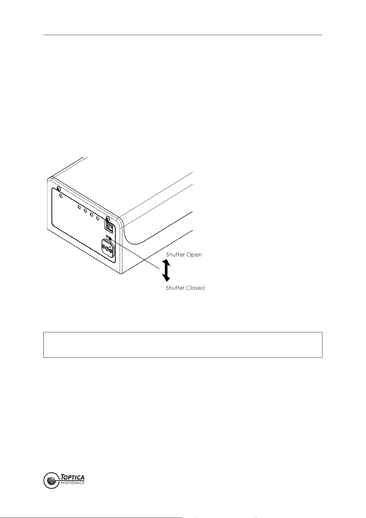
2.4.2 Shutter (Free Beam Version)
Figure 2 FemtoFiber smart shutter operation (only free beam version)
Shift shutter lever up/down as shown in Figure 2 to open/close the laser beam shutter.
2.4.3 Protection Cap on Fiber Pigtail or FC/APC Connector
Due to transport and laser safety, depending on the specification the end of the fiber pigtail at the
FemtoFiber smart or the FC/APC connector is protected by a cap. It must be removed before the first
usage of the laser module.
NOTE ! When the emission of the FemtoFiber smart laser is switched on with closed shutter, back
reflections from the shutter may disturb the internal photo diode/power regulation. This
may lead to unexpected error messages, but is not harmful to the laser.

FemtoFiber smart Manual 3. Installation
Page 11
Status: 6.9.18
3 Installation
3.1 Package Contents
Depending on the order, the complete FemtoFiber smart System consists of the following parts:
1 FemtoFiber smart Laser
1 FemtoFiber smart Manual (optional)
1 Production and Quality Control Data Sheet
when ordered with Switch Box (optional):
1SwitchBox
1 D-Sub 9 Cable (Switch Box/FemtoFiber smart Laser)
1 FemtoFiber smart Power Supply with mains cable
when ordered wit FIBEROUT option:
1F
IBEROUT FemtoFiber smart IR Fiber Collimator (optional)
only FemtoFErb 1560 FD6.5
1 Single Mode PM 1560 Fiber with FC/APC connectors on both sides (optional)
FemtoFiber smart Manual 3. Installation
Page 12
Status: 6.9.18
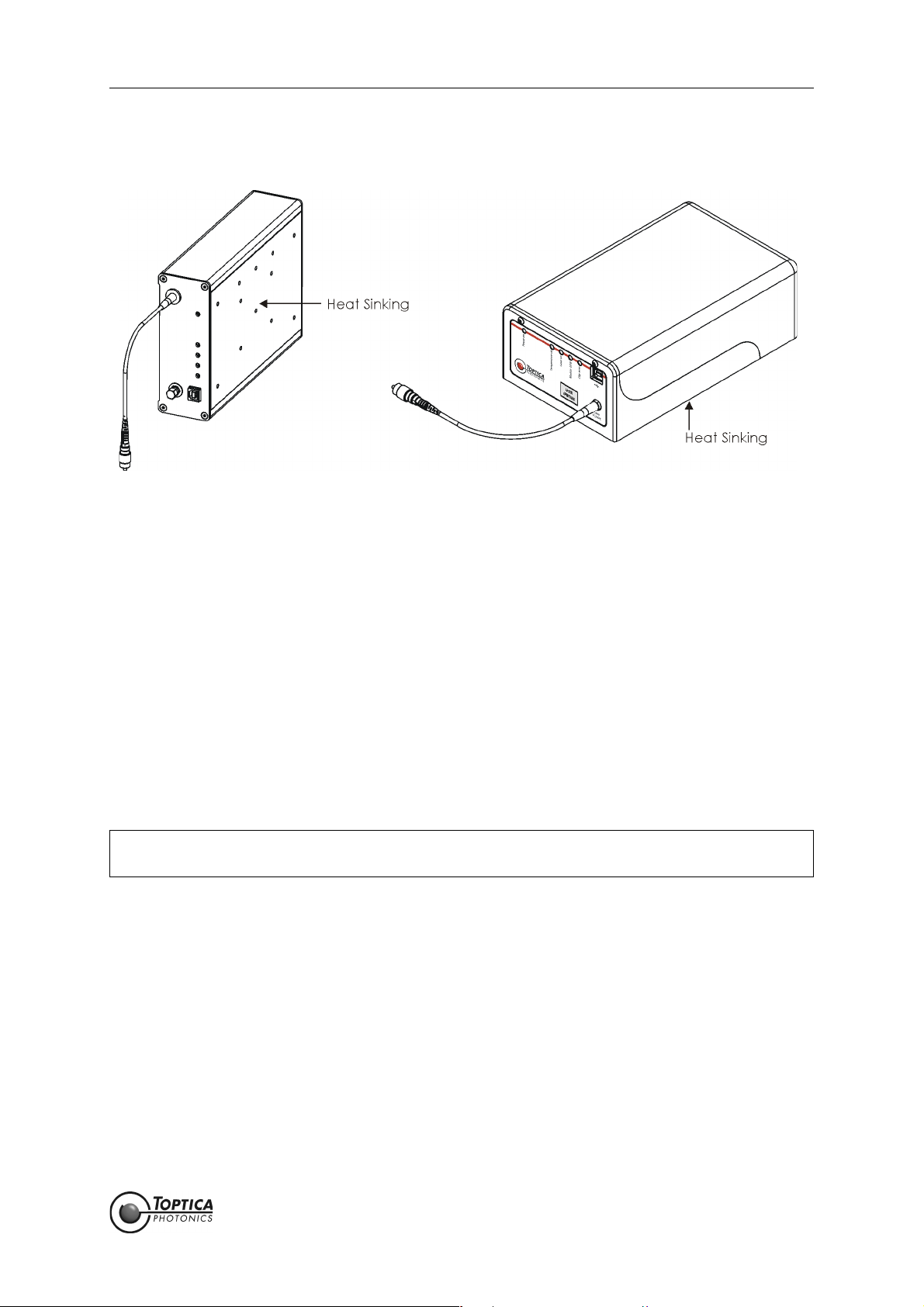
3.2 Installation Instructions
Figure 3 FemtoFiber smart laser (Femto/PicoFYb (left), FemtoFErb (right))
When installing the FemtoFiber smart laser the following instructions have to be observed:
• The FemtoFiber smart laser can be installed in any position. The protective housing has M4 threads
for fixing the FemtoFiber smart laser with screws (for main dimensions of the FemtoFiber smart lasers
and the location and depth of the M4 threads please see section 6.10).
• The FemtoFiber smart laser should only be installed at place free from vibrations.
• The FemtoFiber smart laser is designed for indoor usage, at altitudes below 2000 m.
• Environmental operating conditions: +15 °C .. +40 °C, the air humidity may not lead to condensa-
tion at or inside the laser housing. For a dew point table please refer to section 6.8.
Environmental transport/storage conditions: 0 °C .. +40 °C, non condensing.
• Weight: < 2.2 kg
• Depending on the individual system, the laser beam emits from the FC/APC connector(s) at the
FemtoFiber smart front panel, from the FC/APC-connector at the end of the fiber pigtail or free
beam. For location of the laser beam apertures please refer to section 6.10.
• For maximum stability, heat sinking of the base plate of the FemtoFiber smart laser to a typical
temperature of 22 ±2° C is recommended.
Heat Dissipation: FYb laser heads typ. < 10 W, FErb laser heads typ. < 20 W.
CAUTION ! Avoid back reflection of the laser beam above 100 % (caused e.g. by a connected laser
amplifier).

FemtoFiber smart Manual 4. Operation
Page 13
Status: 6.9.18
4Operation
4.1 Operator Controls FemtoFiber smart Laser
Figure 4 Front and rear panel of FemtoFiber smart laser (FemtoFErb (top), Femto/PicoFYb (bottom))
1Power ON LED 4Module Error LED 7Laser Output
2Temperature OK LED 5Clip Error LED 8Trigger Out
3Laser ON LED
(Laser Radiation Emission
Warning LED)
6USB-connector 9I/O D-Sub 9 Connector

FemtoFiber smart Manual 4. Operation
Page 14
Status: 6.9.18
1 Power ON LED The Power ON LED (blue, 1) lights up when the supply voltage
(12 ± 2 V DC filtered) is applied to the respective pins of the D-Sub 9-con-
nector (9). For pin assignment please see section 6.2.
2 Temperature OK LED The Temperature OK LED (green, 2) lights up after the system is internally
stabilized and ready for operation.
3LaserONLED
(Laser Radiation
Emission Warning
LED)
The Laser ON LED (orange, 3) indicates that the TTL input (Pin 7 of Input/
Output connector (9)) is in state high, i.e. the laser is ON and the laser
beam is emitted from the Laser Output (7).
DANGER ! When the orange Laser ON LED (Laser Radiation Emission
Warning LED) lights up, one has to be aware of laser emission.
4 Module Error LED The Module Error LED (red, 4) indicates a faulty connection between
Switch Box and laser head or a laser internal error. When the LED (4) lights
up continuously, please contact TOPTICA.
5 Clip Error LED The Clip Error LED (yellow, 5) indicates that the laser did not start to oper-
ate after the TTL input (Pin 7 of Input/Output connector (9)) was set to
state high. When the LED (5) lights up continuously, please contact TOP-
TICA.
6 USB-connector USB output connector type B for computer connection and control via
terminal program.
7 Laser Output FemtoFErb 780 Free beam laser output with mechanical shutter.
PicoFYb 1030/1064 FC/APC connector with connector tolerance for
FemtoFYb 1030 polarization maintaining fibers (narrow key,
2.02 mm)
FemtoFErb SC
FemtoFErb 1560 FD6.5 One FC/APC connector with connector tolerance
for polarization maintaining fibers (narrow key,
2.02 mm).
FemtoFErb 1560 Fiber pigtail (approx 20 cm long) with 3 mm cevlar
reinforced tubing and FC/APC-connector at the
end.
8TriggerOutput
• SMA-connector
Output synchronous to the laser pulses for monitoring or triggering pur-
poses (please refer to the Production and Quality Control Data Sheet for
signal properties).
NOTE ! FemtoFErb systems are using the direct output of a photo
diode as Trigger signal. There is no further (amplifying) elec-
tronics in order not to increase the signal jitter. Hence the
amplitudes of the signal are low, in the range of a few tens of
millivolts by nature. Please refer to the Production and Quality
Control Data Sheet for individual values.
9 Input/Output
•D-Sub9-connector
General I/O connector for FemtoFiber smart operation. For pin assignment
please see section 6.2.

FemtoFiber smart Manual 4. Operation
Page 15
Status: 6.9.18
4.2 Operator Controls FemtoFiber smart Switch Box
Figure 5 Front and rear panel of FemtoFiber smart Switch Box
10 ON/OFF Switch 15 Power LED 21 Laser Power Input
11 Main Power Key Switch 16 FemtoFiber smart Supply LED 22 FemtoFiber smart Connector
12 Laser ON Push Button 17 FemtoFiber smart Error LED 23 Power Supply Connector
13 Micro Mover Push Button 18 Laser ON LED
(Laser Radiation Emission
Warning LED)
24 Laser ON Input
14 Pump Laser Power 19 Micro Mover LED 25 Interlock Connector
Adjustment 20 Power Monitor Output

FemtoFiber smart Manual 4. Operation
Page 16
Status: 6.9.18
10 ON/OFF Switch FemtoFiber smart Switch Box voltage supply and laser voltage supply are
switched ON/OFF by switch (10).
11 Main Power Key
Switch
General Switch for Switch Box voltage supply.
12 Laser ON Push Button Push button switches laser emission ON/OFF. Laser emission is indicated by
the Laser ON LED (18).
13 Micro Mover Push
Button
FYb Systems: When the laser does not start after the Laser ON Push But-
ton (12) has been pressed (i.e. the Clip Error LED (5) lights
up), the mirror chip inside the laser head can be moved
slightly by pressing the push button (13) twice.
Please note that the mirror chip can only be moved with
the laser emission switched off.
FErb Systems: Not supported.
14 Pump Laser Power
Adjustment
FErb Systems: Adjustment of the pump diode current from 90 % to 110 %
of the nominal pump diode current.
The zero position on the dial is equal to 90 %, while posi-
tion 10 is equal to 110 %. The pump laser current adjust-
ment can be used for fine tuning of the pulse
characteristics.
NOTE ! For normal operation, please leave the trimpot in mid position
(5 = 100 %) ! The system is checked and certified only for trim-
pot position 5. TOPTICA Photonics AG does not guarantee that
the specifications of the laser are met at all other trimpot set-
tings. Please refer to the Production and Quality Control Test
Data Sheet for specified values
FYb Systems: Adjustment of the pump diode current from 90 % to 100 %
of the nominal pump diode current.
The zero position on the dial is equal to 90 %, while posi-
tion 10 is equal to 100 %. The pump laser current adjust-
ment can be used for fine tuning of the pulse
characteristics.
NOTE ! For normal operation, please leave the trimpot in end position
(10 = 100 %) ! The system is checked and certified only for trim-
pot position 10. TOPTICA Photonics AG does not guarantee that
the specifications of the laser are met at all other trimpot set-
tings. Please refer to the Production and Quality Control Test
Data Sheet for specified values
15 Power LED This green LED indicates proper voltage supply of the Switch Box.
16 Supply LED The Supply LED (blue, 16) lights up when the supply voltage is applied to
the FemtoFiber smart laser.
17 Error LED The Error LED (red, 17) indicates a faulty connection between Switch Box
and laser head or a laser internal error. When the LED (17) lights up contin-
uously, please contact TOPTICA.
18 Laser ON LED
(Laser Radiation
Emission Warning
LED)
The Laser ON LED (orange, 18) indicates that the laser is ON and the laser
beam is emitted from the Laser Output (7).
DANGER ! When the orange Laser ON LED (Laser Radiation Emission
Warning LED) lights up, one has to be aware of laser emission.

FemtoFiber smart Manual 4. Operation
Page 17
Status: 6.9.18
19 Micro Mover LED FYb Systems: The Micro Mover LED (19) lights up after one push at the
Micro Mover Push Button (13) and goes off after the sec-
ond push, when the mirror chip has been moved.
FErb Systems: Not supported.
20 Power Monitor Output
• SMA-connector
Oscillator Power Monitoring, Output Voltage 0 .. 4.5 V for 0 .. 100 %
(does not represent the laser output power exactly)
21 Laser Power Input
• SMA-connector
Input for Analog Laser Power Control (for details please refer to section
6.3).
FErb Systems: 0..5mAviaR=1kΩ, Range 90 - 110 % additional to the
Pump Laser Power Adjustment (14).
FYb Systems: 0..5mAviaR=1kΩ, Range 90 - 100 % additional to the
Pump Laser Power Adjustment (14).
NOTE ! When the laser power is controlled via the Laser Power Input
(21), the Pump Laser Power Adjustment potentiometer (14)
should be turned to min. position to avoid interference
between the two controls.
22 FemtoFiber smart
Connector
•D-Sub9-connector
Connection to the FemtoFiber smart laser.
23 Power Supply
Connector
Connection to the FemtoFiber smart Power Supply.
For pin assignment please refer to section 6.5.
24 Laser ON Input
• Tyco AMP 828549
connector
Input to switch laser emission ON/OFF.
TTL high (+ 3.3 V..+ 5 V) Laser ON, TTL low (0 V..+ 0.8 V) Laser OFF.
Laser emission is indicated by the Laser ON LED (18).
For pin assignment please refer to section 6.4.
25 Interlock Connector
• Phoenix MC0.5/2-G-
2.5 connector
Connector for installation of an external interlock circuit. For first operation,
an interlock plug is supplied to close the interlock circuit. For safety rea-
sons, the installation of an external interlock circuit is strongly recom-
mended.

FemtoFiber smart Manual 4. Operation
Page 18
Status: 6.9.18
4.3 FemtoFiber smart System Quickstart
4.3.1 OEM Integrated Environment
1. Connect the FemtoFiber smart laser to the application via the I/O connector (9). For pin assign-
ment please see section 6.2.
2. Connect the FemtoFiber smart laser Output FC/APC connector (7) to the application.
3. When the FemtoFiber smart laser supply voltage (pin 1 of the I/O connector (9)) is applied and the
TTL input (pin 7 of the I/O connector (9)) is in state high, the laser emission is ON.
CAUTION ! Since the FemtoFiber smart has power levels which may already destroy optical fibers,
please pay special attention to a clean fiber facet at the output fiber connector. We also
recommend to always switch-off the laser emission before the fiber connector is opened/
closed!
CAUTION ! While starting the laser it may occur that higher level pulses are sent out by the laser. This
transient phenomenon is due to the fact that the amplifier of the system starts simulta-
neously with the oscillator. We therefore recommend blocking the output beam at the
moment when the laser is switched on, or adding the THz option.
NOTE ! The FemtoFiber smart is specified to be ready for operation within 15 seconds after switch-
on, provided that the laser emission start signal is given right after the boot-up sequence,
which takes approx. 3 seconds. The end of the boot-up sequence is indicated at the laser
head when the Power ON LED (1, blue) and the Temperature OK LED (2, green) light up
(all other LEDs are off).
If laser emission is activated before reaching this state, an error may occur, indicated by
the Clip Error LED (3, yellow) or Module Error LED (4, red).
Table of contents
Other Toptica Measuring Instrument manuals


