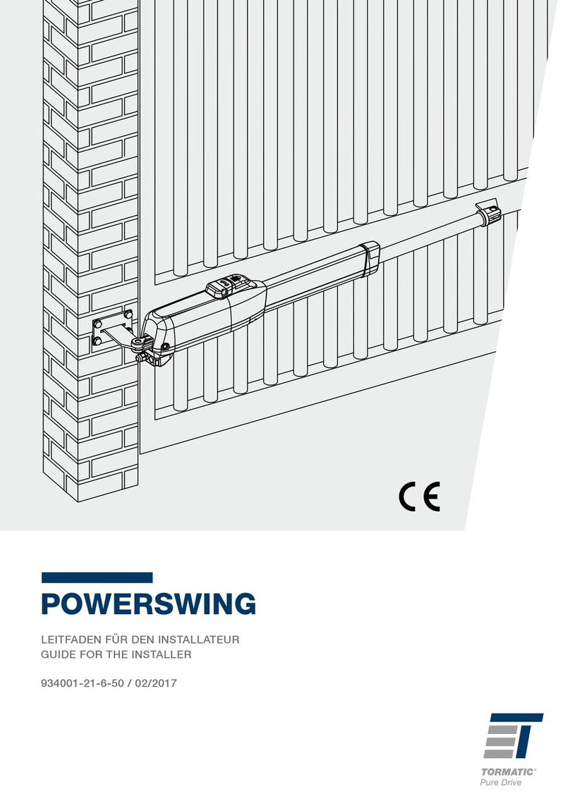
Tormatic NovoSwing Service manual

D - Montage- und Bedienungsanleitung
GB - Mounting and operating instructions
F -
NL -
E -
P -
I -
DK -
SE -
N -
FI -
NovoSwing
WN 020795 31/2010

Innhaltsverzeichnis D
Hinweise
- Allgemeine Informationen
- Leistungsangaben
- Allgemeine Merkmale
- Vorkontrollen
Bedienungsanleitung
- Funktionen
- Sicherheitseinrichtungen
Montage der Steuerung
Montage der Antriebseinheit
Inbetriebnahme der Steuerung
- Übersicht
- Hauptmenüs
- Programmierablauf
- Funk einlernen
- Einstellen der Torendlagen
- Krafteinstellungen
- Leuchtzeiten
- Softlaufstrecken
- Verzögerungen
- Sonderfunktionen
- Betriebsarten
- Offenhaltezeiten
- Sonder
Anschlußschema
Kabelplan
Motoranschluß
Lichtschranken
Anschlußschema
- Lichtschranken LS 2 / LS 5
-E-Schloß
Fehlermeldungen
Konformitätserklährung / Prüfliste Toranlage
Prüfbuch / Prüfliste

Installation and operating instructions GB
Notices
- General information
- Specifications
- General features
- Preliminary inspections
Operating instructions
- Functions
-Guards
Installation of the control
Installation of the drive unit
Start-up of the control
-Overview
- Main menus
- Programming sequence
- Teaching
- Setting the gate end positions
- Force settings
- Light times
- Soft run distances
- Delays
- Special functions
- Operating modes
- Hold-open times
- Special functions
Wiring schematics
Cable plan
Motor connection
Light barriers
Wiring schematics
- Light barriers LS 2 / LS 5
- Electric lock
Error messages
Conformity declaration / gate system checklist
Inspection log / inspection list

Sicherheitsrelevante Vorschriften
Bei der Installation, Inbetriebnahme, Wartung und
Prüfung der Steuerung müssen die örtlichen
Schutzbestimmungen eingehalten werden!
Hersteller: Novoferm tormatic GmbH
Oberste-Wilms-Str. 15a
D-44309 Dortmund
Hinweise D
Allgemeine Informationen
Sicherheit
Vor Beginn sämtlicher Arbeiten am Produkt die Betriebsanleitung,
insbesondere das Kapitel Sicherheit und die jeweiligen
Sicherheitshinweise, vollständig lesen. Das Gelesene muss
verstanden worden sein. Es könnten von diesem Produkt
Gefahren ausgehen, wenn es nicht fachgerecht, unsachgemäß
oder nicht bestimmungsgemäß verwendet wird. Bei Schäden, die
aufgrund der Nichtbeachtung dieser Anleitung entstehen, erlischt
die Herstellerhaftung.
ACHTUNG:
WICHTIGE SICHERHEITSANWEISUNG
FÜR DIE SICHERHEIT VON PERSONEN IST ES WICHTIG;
DIESEN ANWEISUNGEN FOLGE ZU LEISTEN: DIESE
ANWEISUNGEN SIND AUFZUBEWAHREN
ACHTUNG:
WICHTIGE ANWEISUNGEN FÜR SICHERE MONTAGE, ALLE
ANWEISUNGEN BEACHTEN; FALSCHE MONTAGE KANN ZU
ERNSTHAFTEN VERLETZUNGEN FÜHREN.
Veränderungen und Umbauten am Produkt
Zur Vermeidung von Gefährdungen und zur Sicherung der
optimalen Leistung dürfen am Produkt weder Veränderungen
noch An- und Umbauten vorgenommen werden, die durch den
Hersteller nicht ausdrücklich genehmigt worden sind.
Typenschild
Das Typenschild befindet sich seitlich am Motorkopf. Die
angegebenen Anschlusswerte sind zu beachten.
Arbeitssicherheit
Durch Befolgen der angegebenen Sicherheitshinweise und
Anweisungen in dieser Betriebsanleitung können Personen- und
Sachschäden während der Arbeit mit und an dem Produkt
vermieden werden.
Bei Nichteinhaltung der angegebenen Sicherheitshinweise und
Anweisungen in dieser Betriebsanleitung sowie die für den
Einsatzbereich geltenden Unfallverhütungsvorschriften und
allgemeinen Sicherheitsbestimmungen sind jegliche Haftpflicht-
und Schadenersatzansprüche gegen den Hersteller oder seinen
Beauftragten ausgeschlossen.
Gefahren,
die vom Produkt ausgehen können
Das Produkt wurde einer Gefährdungsanalyse unterzogen.
Die darauf aufbauende Konstruktion und Ausführung des
Produktes entspricht dem heutigen Stand der Technik.
Das Produkt ist bei bestimmungsgemäßer Verwendung
betriebssicher. Dennoch bleibt ein Restrisiko bestehen!
Das Produkt arbeitet mit hoher elektrischer Spannung. Vor
Beginn der Arbeiten an elektrischen Anlagen ist folgendes zu
beachten:
1. Freischalten
2. Gegen Wiedereinschalten sichern
3. Spannungsfreiheit feststellen
Symbolerklärung
WARNUNG: DROHENDE GEFAHR
Dieses Symbol kennzeichnet Hinweise, die
bei Nichtbeachtung zu schweren
Verletzungen führen können.
WARNUNG! GEFAHR DURCH
ELEKTRISCHEN STROM
Die ausführenden Arbeiten dürfen nur von
einer Elektrofachkraft ausgeführt werden.
Dieses Symbol kennzeichnet Hinweise,
die bei Nichtbeachtung zu Fehlfunktionen
oder und/oder Ausfall des Antriebes führen
können.
!
Ersatzteile Nur Original-Ersatzteile des Herstellers
verwenden. Falsche oder fehlerhafte
Ersatzteile können zu
Beschädigungen, Fehlfunktionen oder
Totalausfall des Produktes führen.
Demontage
Die Demontage erfolgt in umgekehrter Reihenfolge der
Montageanleitung 13 - 1.
Verpackung
Entsorgung der Verpackungsmaterialien stets umweltgerecht
und nach den geltenden örtlichen Entsorgungsvorschriften
vornehmen.
Entsorgung
Es sind die entsprechenden Ländervorschriften zu beachten.
Kunststoffteile entsprechend sortieren:

Dismantling
Dismantling takes place in reverse sequence to the
Installation Instructions 7- 1.
Producer: Novoferm tormatic GmbH
Oberste-Wilms-Str. 15a
D-44309 Dortmund
Notices GB
General Information
Safety
Before commencing any work on the product,
carefully read through the operating instructions
from start to finish, in particular the section entitled
"Safety" and the related safety advice. It is
important for you to have understood what you
have read. This product could prove hazardous if
not used properly as directed or in accordance with
the regulations.
Any damage occurring as a result of noncompliance
with these instructions shall render the
manufacturer's liability null and void.
ATTENTION
IMPORTANT SAFETY ADVICE
TO ENSURE THE SAFETY OF PERSONS, IT IS NECESSARY
TO OBSERVE THESE INSTRUCTIONS.
RETAIN THESE INSTRUCTION MANUAL.
ATTENTION
IMPORTANT INSTRUCTIONS TO ENSURE A SAFE
INSTALLATION.
PLEASE OBSERVE THESE INSTRUCTIONS.
INCORRECT INSTALLATION COULD LEAD TO SERIOUS
INJURIES.
Changes and modifications to the product
To prevent hazards and ensure optimum
performance, no changes, modifications or
conversions may be made to the product that have
not been expressly approved by the manufacturer.
Working safety
By complying with the safety advice and
information provided in these Operating
Instructions, injury to persons and damage to
property whilst working on and with the product
can be avoided.
Failure to observe the safety advice and
information provided in these Operating
Instructions as well as the accident prevention and
general safety requirements relevant to the field of
application shall exempt the manufacturer or its
authorized representatives from all liability and
shall render any damage claims null and void.
Hazards that may emanate from the product
The product has been subjected to a risk
assessment. The design and execution of the
product based on this corresponds to state-of-theart
technology.
When used properly as intended, the product is
safe and reliable to operate.
Nevertheless, a residual risk will always remain!
The product runs on a high electrical voltage.
Before commencing any work on electrical
systems, please observe the following:
1. Disconnect from the power supply
2. Safeguard to prevent a power restart
3. Check that the electricity supply is cut off
Explanation of the symbols
WARNING: imminent danger
This symbol indicates that instructions are
being given which, if not observed,
could lead to serious injury
WARNING: DANGER DUE TO ELECTRIC
VOLTAGE. The works have to be done by an
electrican.
Attention ! This symbol indicates that
instructions are being given which, if not
observed, could lead to malfunctions and / or
failure of the operator.
!
Spare parts
Only use genuine spare parts of the
manufacturer.Wrong or faulty spare parts
can cause damage, malfunctions or even
a total failure of the product.
Disposal
Observe the corresponding country-specific
regulations.
Packaging
Always dispose of the packaging in an
environmentally-friendly manner and in
accordance with the local regulations on disposal.
Data plate
The data plate is located under the control panel
cover. Observe the specified power rating.

Bedienungsanleitung
Diese Betriebsanleitung beschreibt den sicheren und
sachgerechten Umgang mit dem Produkt. Die angegebenen
Sicherheitshinweise und Anweisungen sowie die für den
Einsatzbereich geltenden örtlichen
Unfallverhütungsvorschriften und allgemeinen
Sicherheitsbestimmungen müssen eingehalten werden.
Weisen Sie alle Personen, die die
Toranlage benutzen, in die Ordnungsgemäße
und sichere Bedienung ein.
Handsender gehören nicht in die Hände
von Kindern.
Bei Betätigung des Antriebes müssen
die Öffnungs- und Schließvorgänge
überwacht werden. Im Fahrbereich des
Tores dürfen sich keine Personen oder
Gegenstände befinden.
Wartung / Überprüfung
Die Toranlage ist vor der ersten Inbetriebnahme
und nach Bedarf jedoch mindestens einmal
jährlich von einem Fachbetrieb prüfen zu lassen.
Achtung!
Eine zu hoch eingestellte Schließkraft kann zu
Verletzungen von Personen oder zu
Sachschäden führen.
Achtung!
Installation und Inbetriebnahme nur durch
technisch unterwiesene Personen
PRÜFEN DER Toranlage
Vor Beginn des Einbaus sollte überprüft werden, ob der
Antrieb für diesen Anwendungszweck geeignet ist, unter
Berücksichtigung der Eigenschaften und Abmessungen des
Tores (siehe Leistungsdaten).
• Die korrekte Wahl des bestgeeigneten Antriebes sichert
einen sachgemäßen Betrieb und verringert zugleich anfällige
Störfälle.
• Der Antrieb entspricht (sofern fachgerecht installiert) den
Sicherheitsnormen.
ALLGEMEINE MERKMALE
• Der elektromechanische Antrieb NovoSwing ist für
Drehflügeltore bis 1,8 Meter Flügelbreite entwickelt worden.
• Bei Toren bis 1,8 Meter Flügelbreite erspart man sich den
Einbau eines Elektroschlosses. Dabei bleibt die
Schließstellung gewährleistet.
• Not-Entriegelung: Ermöglicht den Handantrieb des Tores (bei
Stromausfall zu verwenden) mit einem Schlüssel. Die
Entrigelung ist leicht zugänglich an der Unterseite des
Antriebes.
• Die Steuerung ist im Sichtbereich des Tores zu montieren.
VORKONTROLLEN
Vor Bestimmung der Drehpunkte sind folgende Arbeitsgänge
erforderlich:
• Die bestgeeignete Stelle am Flügel für die Montage
aussuchen. Den Drehpunkt nach Möglichkeit auf halber
Flügelhöhe positionieren. Sofern sich am Tor kein
strukturabhängiger Profilstab befindet, ist an die für den
vorderen Drehpunkt geeignete Stelle ein passender
Halter aufzuschweißen. Damit wird die Belastung auf eine
breite Fläche verteilt.
• Vor der endgültigen Montage ist eine gründliche Kontrolle
der Flügel erforderlich. Nachprüfen, ob diese in tadellosem
Zustand sind und weder Brüche noch Schäden aufweisen.
•Torflügel auf Gängigkeit prüfen
• Prüfen, ob sich die Scharniere reibungslos und spielfrei
bewegen.
ELEKTROANSCHLUSS
Bei Durchführen der Kabelanschlüsse sind die
mitgelieferten Anleitungen zu den einzelnen
Komponenten und das Schaltschema sorgfältig
zu befolgen.
Die Antriebe sind nur für das Öffnen und das
Schließen von Drehtoren bestimmt. Der Hersteller
haftet nicht für Schäden, die durch andere
Benutzung der angegeben Leistungsdaten
entsteht.
Leistungsdaten
Max. Torgewicht 200 Kg
Max. Flügellänge 1,8 m
Min. Flügellänge 0,8 m
Max. Torhöhe 2,0 m
Torblattfläche min 50% Winddurchlässig
Anschlussspannung 230 V + - 10 % 50 Hz
Leistungsaufnahme 250 W
Betriebstemperatur -20 °C / +60 °C
Schubkraft 1500 N
Zugkraft 1500 N
Öffnungs- und Schließzeit 19 Sek.
HUB 350 mm
ED 30%
Soft Start / Stopp regelbar
Externe 24VAC Sicherung 5x20 mm
3,15 AT
Hinweise D
Achtung!
Wenn die Netzanschlußleitung dieses Gerätes
beschädigt oder ersetzt werden soll, muß dieses
durch eine qualifizieret oder technisch
unterwiesene Person durchgeführt werden um
Gefährdungen zu vermeiden.

Operating instructions
These operating instructions describe the safe and proper
handling of the product. All safety and general instructions
relating to the product and all local accident prevention
regulations and general safety instructions should strictly be
followed.
Instruct all persons who use the gate system in its
proper and safe use.
Keep hand-held transmitters out of reach of
children.
Closely observe all opening and closing
movements of the gate when actuating the drive.
For safety reasons, no persons or objects are
permitted in the movement area of the gate.
Maintenance / inspection
The gate system should be inspected by a
specialist firm before the first start-up and as
needed but at last once every year.
Caution!
The closing force, if set too high, can cause injury
to persons or damage to assets.
Caution!
Installation and start-up only by persons after
technical instruction
Testing the gate system
Before starting installation work, check to make sure that the
drive can be used for the purpose for which you need it
considering the properties and dimensions of the gate (see
specifications).
• The right choice of the best-suited drive ensures proper
operation of the gate and reduces failure.
• (If installed properly) the drive complies with the applicable
safety requirements.
General features
• The NovoSwing electromechanical drive has been developed
for swing wing doors of up to 1.8 meters wing width.
• Gates up to 1.8 meters wing width do not require an electric
lock. The lock position is maintained.
• Emergency release: For manual movement of the gate (in
case of power failure) with a key. The unlock mechanism is
easily accessible at the underside of the drive.
Install the control at a place from where you can see the gate.
PRELIMINARY INSPECTIONS
Complete the following steps before defining the fulcrums:
• Define the point on the wing that is best for installation. If
possible, position the fulcrum at half wing height. If the gate
has no structural sectional bar, weld a holder to the point
suitable for the front fulcrum. This spreads the load on a wide
area.
• Before starting installation proper, make a thorough
inspection of the wings. Inspect the state of the wings and look
for cracks and damage.
Check to make sure that the wings are moving easily
• Check the hinges for ease of movement without play.
Electrical connection
When making the cable connections, observe the
instructions in the manuals of components and
the wiring schematics.
The drives should only be used for the opening
and closing of turning gates. The supplier is not
responsible for damage caused due to any other
use of the specifications in this manual.
Specifications
Max. gate weight 200 kg
Max. wing length 1.8 m
Min. wing length 0.8 m
Max. gate height 2.0 m
Door wing area min 50% wind-
permeable
Supply voltage 230 V + - 10 % 50 Hz
Power consumption 250 W
Operating temperature -20 °C / +60 °C
Thrust 1500 N
Pull 1500 N
Opening and closing time 19 secs.
Stroke 350 mm
Duty cycle 30%
Soft start / stop controlled
Extern 24 VAC fuse 5x20 mm
3,15 AT
Notices GB
Caution!
If the mains power cable of the device is
damaged or needs replacement, have a skilled
person who has received technical instructions do
this in order to avoid danger.

Automatisches Schließen (2)
Impulsgabe bewirkt immer ein Öffnen des Tores.
Nach Ablauf der Offenhaltezeit und der Vorwarnzeit
schließt das Tor automatisch.
Automatisches Schließen (3)
Impulsgabe bewirkt immer ein Öffnen des Tores.
Nach Ablauf der Offenhaltezeit und der Vorwarnzeit
schließt das Tor automatisch.
Bei Unterbrechung der Lichtschranke wird die
Offenhaltezeit vorzeitig abgebrochen und die
Vorwarnzeit wird gestartet.
Automatisches Schließen (4)
Impulsgabe bewirkt immer ein Öffnen des Tores.
Nach Ablauf der Offenhaltezeit und der Vorwarnzeit
schließt das Tor automatisch.
Bei erneuter Impulsgabe wird die Offenhaltezeit
vorzeitig abgebrochen und die Vorwarnzeit wird
gestartet.
Automatisches Schließen mit Start-Stop Funktion
(5)
Impulsgabe bewirkt immer ein Öffnen des Tores.
Nach erreichen der Tor-Auf Position kann innerhalb von
3 sec. durch eine Impulsgabe das Automatische
Schließen unterbrochen werden. Im Display wird die „6“
angezeigt. Durch einen erneuten Impuls wir das
Automatische Schließen wieder aktiviert.
Normalbetrieb (0)
(werksseitig eingestellte Betriebsart)
Der Drehtorantrieb kann durch Impulsgeber wie
Handsender, Schlüsseltaster usw. betätigt werden. Es
ist nur eine kurze Impulsgabe erforderlich.
Funktionsablauf:
Erste Impulsgabe:
Antrieb startet und fährt Tor in die eingestellte
Endposition AUF oder ZU.
Impulsgabe während der Fahrt:
Tor stoppt.
Erneuter Impuls:
Tor setzt in entgegengesetzter Richtung den Lauf fort.
Gehflügelsteuerung (nur im Normalbetrieb)
Bei zweiflügeligen Toren besteht die Möglichkeit, mit
dem Zweiten Kanal vom Handsender. nur einen
Torflügel zu öffnen und zu schließen.
AUF-ZU-Betrieb (1)
Funktionsablauf:
Impulsgabe in Zu-Position
Antrieb startet und fährt Tor in die Tor-Auf-Position.
Impulsgabe während der Auffahrt
Ohne Einfluß Tor fährt weiter auf.
Impulsgabe in Auf-Position:
Tor fährt zu.
Impulsgabe während der Zufahrt:
Tor stoppt und fährt wieder auf.
Funktionen der Sicherheitseinrichtungen
Interne Kraftbegrenzungseinrichtung
Läuft das Tor während der Zu-Fahrt auf ein Hindernis,
stoppt der Antrieb und gibt das Hindernis durch Öffnen
wieder frei.
Während des Softlaufs der Zu-Fahrt wird das Tor nur
einen Spalt breit geöffnet um das Hindernis
freizugeben.
Läuft das Tor während der Öffnungsfahrt auf ein
Hindernis, stoppt der Antrieb und kehrt die
Fahrtrichtung für ca. eine Sekunde um.
Lichtschranke Stop B
Ist eine Lichtschranke installiert, bewirkt diese bei
Unterbrechung während der Schließfahrt ein Stoppen
und eine Richtungsumkehr. Während der Öffnungsfahrt
hat eine Unterbrechung keinen Einfluß.
Lichtschranke Stop A
Ist eine Lichtschranke installiert, bewirkt diese bei
Unterbrechung während der Fahrt ein Stoppen der
Toranlage.
Entriegelung des Antriebs
(nur bei abgeschalteter
Netzspannung)
Bei Einstellarbeiten, Stromausfall oder
Störungen kann das Tor entriegelt und von
Hand betätigt werden. Mit dem
Dreikantschlüssel das auf der Unterseite
befindliche Rad entriegeln und nach unten
klappen. Das Tor lässt sich manuell öffnen
und schießen.
Toranschläge
Es muss ein Anschlag für die Referenzfahrt in der
Auf-Position gesetzt werden. Dieser muß min. 5 mm
hinter der normalen Tor- Auf Position installiert werden.
Vorzugsweise sollte der intern Anschlage genutzt
werden.
Während der Lernfahrt wird der mechanische Anschlag
einmalig angefahren und dient als Referenzpunkt.
In der normalen Funktion stoppt das Tor in der
eingelernten Position
Bedienungsanleitung D
Bitte vor der Montage sorgfältig lesen!
Montage nur durch entsprechend qualifizierte
Fachkräfte!
Bei falscher Montage kann die Sicherheit von Personen
gefährdet werden!
Die Herstellerhaftung erlischt bei nicht ordnungsgemäß
durchgeführter Montage.

Automatic closing (2)
Any pulse causes the gate to open.
The gate closes automatically at the end of the hold-
open time and the advance warning time.
Automatic closing (3)
Any pulse causes the gate to close.
The gate closes automatically at the end of the hold-
open time and the advance warning time.
When the light barrier is interrupted, the hold-open time
is stopped and the advance warning time starts.
Automatic closing (4)
Any pulse causes the gate to open.
The gate closes automatically at the end of the hold-
open time and the advance warning time.
When another pulse is received, the hold-open time is
stopped and the advance warning time starts.
Automatic closing with the start-stop function (5)
Any pulse causes the gate to open.
When the gate reaches open position, automatic closing
can be interrupted by a pulse sent within 3 seconds.
The figure „6“ is shown in the display. The next pulse
reactivates the automatic closing function.
Normal mode (0)
(Default mode)
The drive of the turning gate can be actuated by a pulse
transmitter such as a hand-held transmitter, key-
operated switch, etc. Short pulses are sufficient.
Functional sequence:
First pulse:
The drive starts and the gate moves to the set OPEN or
CLOSED end position.
Pulse received while the gate is moving:
Gate stops.
Next pulse:
Gate continues moving in the opposite direction.
Active wing control (only for normal mode)
With 2-wing doors, only one wing can be opened and
closed via the second channel of the hand-held
transmitter.
OPENC-CLOSE (1)
Functional sequence:
Pulse received when gate is closed:
The drive starts and the gate moves to the gate open
position.
Pulse received while the gate is moving up:
No effect on the gate
Pulse received while the gate is in up position:
Gate is moving up.
Pulse received while the gate is closing:
Gate stops and then moves open.
Guard functions
Internal force limitation
If the gate hits an obstacle while closing, the drive stops
and moves away from the obstacle in the opposite
direction.
During soft run mode when the gate is closing, it opens
again a little to release the obstacle.
If the gate hits an obstacle while closing, the drive stops
and reverses the movement for about one second.
Light barrier stop B
If a light barrier is installed and that light barrier is
interrupted while the gate is closing, the gate stops and
moves in the opposite direction. Interruption of the light
barrier while the gate is opening has no effect.
Light barrier stop A
If a light barrier is installed and that light barrier is
interrupted while the gate is moving, the gate stops.
Unlocking the drive
(only when mains supply is switched off)
The gate can be unlocked and moved
manually in setting mode, during power
failure or other trouble. Release the wheel
on the underside with the triangular wrench
and fold it down. The gate can now be
opened and closed manually.
Gate stops
A stop should be set for the reference move of the gate
to open position. The stop should be set at least 5 mm
behind the normal door open position.
Preferably, the internal stop should be used.
The mechanical stop is approached once during teach-
in and serves as reference point.
In normal operation, the gate stops at the taught position.
Operating instructions GB
Please read the operating instructions carefully before
starting the installation.
The gate should be installed by skilled technical personnel.
If the installation is wrong, person can be in danger.
The supplier is not responsible for damage caused due to
improper installation.

GB - Installation operating unit
D - Montage Antriebseinheit

Installation operating unitGB - Installation operating unit
D - Montage Antriebseinheit

min 80 mm
Installation operating unitGB - Installation operating unit
D - Montage Antriebseinheit

Installation operating unitGB - Installation operating unit
D - Montage Antriebseinheit

D - Toranschlag AUF
GB - Gate position open
Installation operating unitGB - Installation operating unit
D - Montage Antriebseinheit

D Montage der Steuerung
GB Installation of the control
F
NL
E
P
I
DK
SE
N
FI
182 mm
242 mm
Installation of the control
The base on which the control is installed should be dry, level and vibration isolated. Always install the control
vertically.
Fasten the control by four screws in the outer fastening holes.
The control should be installed where when it is used the movement of the gate or any other aspect of the
gate operation is not a danger to anyone.
Montage der Steuerung
Der Untergrund auf dem die Steuerung befestigt wird, muss trocken, eben, schwingungs- und vibrationsfrei
sein. Die Steuerung ist immer senkrecht zu montieren.
Die Steuerung wird an den vier außenliegenden Befestigungslöchern mit vier Schrauben befestigt.
Die Montage der Steuerung muss so erfolgen, dass für das Bedienungspersonal keinerlei Gefahren durch
Torlauf oder sonstige Einflüsse im Betriebsablauf entstehen.

DSteuerung starten
GB Start-up the control
F
NL
E
P
I
DK
SE
N
FI

DFunk Start
GB Remote start
F
NL
E
P
I
DK
SE
N
FI
DTor Auf-Standflügel/2.Flügel
GB Gate open-inactive wing/ 2 wings
F
NL
E
P
I
DK
SE
N
FI
DTor Zu-Standflügel/2.Flügel
GB Gate close-inactive wing/2 wings
F
NL
E
P
I
DK
SE
N
FI
DTor Zu- Gangflügel / 1 Flügel
GB Gate close – active wing / 1 wing
F
NL
E
P
I
DK
SE
N
FI
D Hauptmenü
GB main menu
F
NL
E
P
I
DK
SE
N
FI
D Steuerung starten
GB Start-up of the control
F
NL
E
P
I
DK
SE
N
FI
DFunk Gehflügelsteuerung
GB Active wing remote control
F
NL
E
P
I
DK
SE
N
FI
DTor Auf- Gangflügel / 1-Flügel
GB Gate Open – active wing / 1 wing
F
NL
E
P
I
DK
SE
N
FI

DOffenhaltezeit bei AR-Betrieb
GB Hold-open times in AR mode
F
NL
E
P
I
DK
SE
N
FI
DBetriebsarten
GB Operating modes
F
NL
E
P
I
DK
SE
N
FI
DSondermenüs
GB Special menu
F
NL
E
P
I
DK
SE
N
FI
DVerzögerung Gehflügel ZU
GB active wing CLOSE delay
F
NL
E
P
I
DK
SE
N
FI
DVerzögerung Standflügel AUF
GB inactive wing OPEN delay
F
NL
E
P
I
DK
SE
N
FI
DKrafteinstellung Auf
GB Force setting Open
F
NL
E
P
I
DK
SE
N
FI
DKrafteinstellung Zu
GB Force setting close
F
NL
E
P
I
DK
SE
N
FI
DLichtzeiten
GB Light times
F
NL
E
P
I
DK
SE
N
FI
DSoftlaufstrecken
GB Soft run distances
F
NL
E
P
I
DK
SE
N
FI

DProgramierablauf
GB Programming sequence
F
NL
E
P
I
DK
SE
N
FI
1x
3 sec.
3 sec.
EXIT

DFunk Start (1) einlernen, Start Gehflügelsteuerung (2)
GB Teaching remote start(1), active wing control start(2)
F
NL
E
P
I
DK
SE
N
FI
1x
5 x
2x
EXIT
2x
5 x
EXIT
1x
Other manuals for NovoSwing
2
Table of contents
Other Tormatic Garage Door Opener manuals
Popular Garage Door Opener manuals by other brands

Chamberlain
Chamberlain Security+ 1215EM FS2 owner's manual

Nice
Nice IN100 Instructions and warnings for installation and use

Genie
Genie Screw Drive Assembly/installation instructions

Tecnoautomazione
Tecnoautomazione T011S user manual

King gates
King gates VIKY30 installation instructions
Automatic Technology
Automatic Technology ATS Series instruction manual
Secom
Secom Catalea VS2 Installation instruction

Craftsman
Craftsman 200.57983 owner's manual

Vitris
Vitris Portavant 120 installation instructions
Merlin
Merlin MJ3800 Installation and operating instructions

PPA
PPA EURUS STEEL 1/2 Technical manual

Beninca
Beninca ZED Operating instructions and spare parts catalogue
