Toro 07068 User manual

FormNo.3395-469RevA
ProSweepTurfSweeper
ModelNo.07068—SerialNo.315000001andUp
Registeratwww.Toro.com.
OriginalInstructions(EN)*3395-469*A

ThisproductcomplieswithallrelevantEuropeandirectives.
FordetailspleaseseetheseparateproductspecicDeclaration
ofConformity(DOC)sheet.
ElectromagneticCompatibility
Domestic:ThisdevicecomplieswithFCCrulesPart15.
Operationissubjecttothefollowingtwoconditions:(1)This
devicemaynotcauseharmfulinterferenceand(2)thisdevice
mustacceptanyinterferencethatmaybereceived,including
interferencethatmaycauseundesirableoperation.
Thisequipmentgeneratesandusesradiofrequencyenergyand
ifnotinstalledandusedproperly,thatis,instrictaccordance
withthemanufacturer'sinstructions,maycauseinterferenceto
radioandtelevisionreception.Ithasbeentypetestedandfound
tocomplywiththelimitsforaFCCClassBcomputingdevice
inaccordancewiththespecicationsinSubpartJofPart15of
FCCRules,whicharedesignedtoprovidereasonableprotection
againstsuchinterferenceinaresidentialinstallation.However,
thereisnoguaranteethatinterferencewillnotoccurina
particularinstallation.Ifthisequipmentdoescauseinterference
toradioortelevisionreception,whichcanbedeterminedby
turningtheequipmentoffandon,theuserisencouragedto
trytocorrecttheinterferencebyoneormoreofthefollowing
measures:Reorientthereceivingantenna,relocatetheremote
controlreceiverwithrespecttotheradio/TVantennaorplug
thecontrollerintoadifferentoutletsothatthecontrollerand
radio/TVareondifferentbranchcircuits.Ifnecessary,theuser
shouldconsultthedealeroranexperiencedradio/television
technicianforadditionalsuggestions.Theusermayndthe
followingbookletpreparedbytheFederalCommunications
Commissionhelpful:"HowtoIdentifyandResolveRadio-TV
InterferenceProblems".ThisbookletisavailablefromtheU.S.
GovernmentPrintingOfce,Washington,DC20402.StockNo.
004-000-00345-4.
FCCID:OA3MRF24J40MC-BASE,
OA3MRF24J40MA-HANDHELD
IC:7693A-24J40MC-BASE,7693A-24J40MA-HANDHELD
Operationissubjecttothefollowingtwoconditions:(1)this
devicemaynotcauseinterference,and(2)thisdevicemust
acceptanyinterference,includinginterferencethatmaycause
undesiredoperationofthedevice.
CAUTION
Ifausermakeschangesormodicationsnot
expresslyapprovedbythepartyresponsiblefor
compliance,theycouldvoidtheuser'sauthorityto
operatetheequipment.
Introduction
Thismachineisintendedtobeusedbyprofessional,hired
operatorsincommercialapplications.Theprimaryfunction
ofthemachineistoremovedebrisfromlargeturfareas.The
movabletongueprovidesanoffsetpositionforsweeping.
Readthisinformationcarefullytolearnhowtooperateand
maintainyourproductproperlyandtoavoidinjuryand
productdamage.Youareresponsibleforoperatingthe
productproperlyandsafely.
YoumaycontactTorodirectlyatwww .Toro.comforproduct
andaccessoryinformation,helpndingadealer,ortoregister
yourproduct.
Wheneveryouneedservice,genuineToroparts,oradditional
information,contactanAuthorizedServiceDealerorToro
CustomerServiceandhavethemodelandserialnumbersof
yourproductready.Figure1identiesthelocationofthe
modelandserialnumbersontheproduct.Writethenumbers
inthespaceprovided.
Figure1
1.Modelandserialnumberlocation
ModelNo.
SerialNo.
Thismanualidentiespotentialhazardsandhassafety
messagesidentiedbythesafetyalertsymbol(Figure2),
whichsignalsahazardthatmaycauseseriousinjuryordeath
ifyoudonotfollowtherecommendedprecautions.
Figure2
1.Safetyalertsymbol
Thismanualuses2wordstohighlightinformation.
Importantcallsattentiontospecialmechanicalinformation
andNoteemphasizesgeneralinformationworthyofspecial
attention.
©2015—TheToro®Company
8111LyndaleAvenueSouth
Bloomington,MN554202
Contactusatwww.Toro.com.
PrintedintheUSA.
AllRightsReserved

Contents
Safety...........................................................................3
SafeOperatingPractices...........................................3
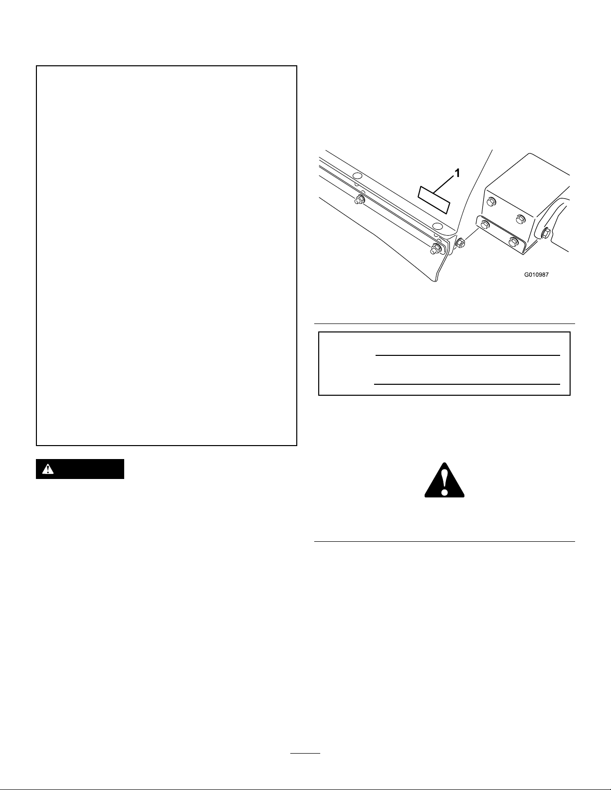
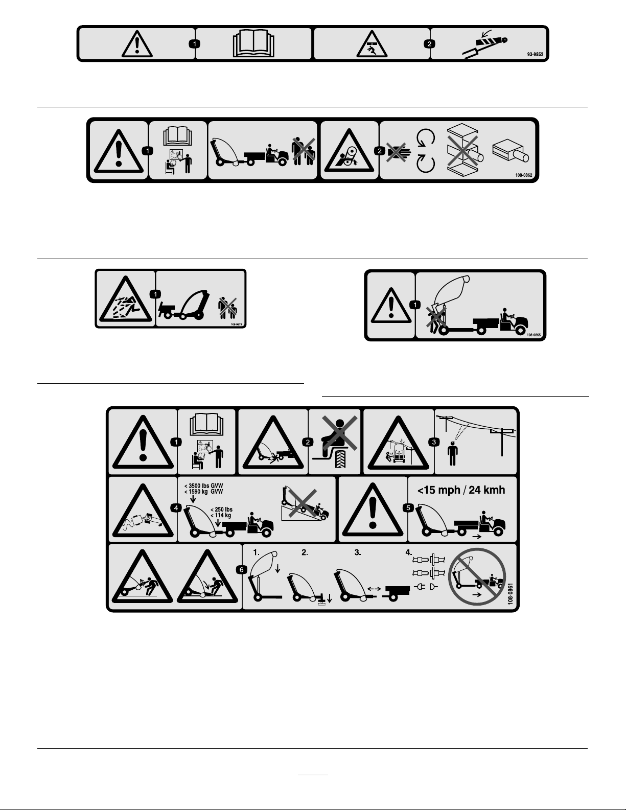
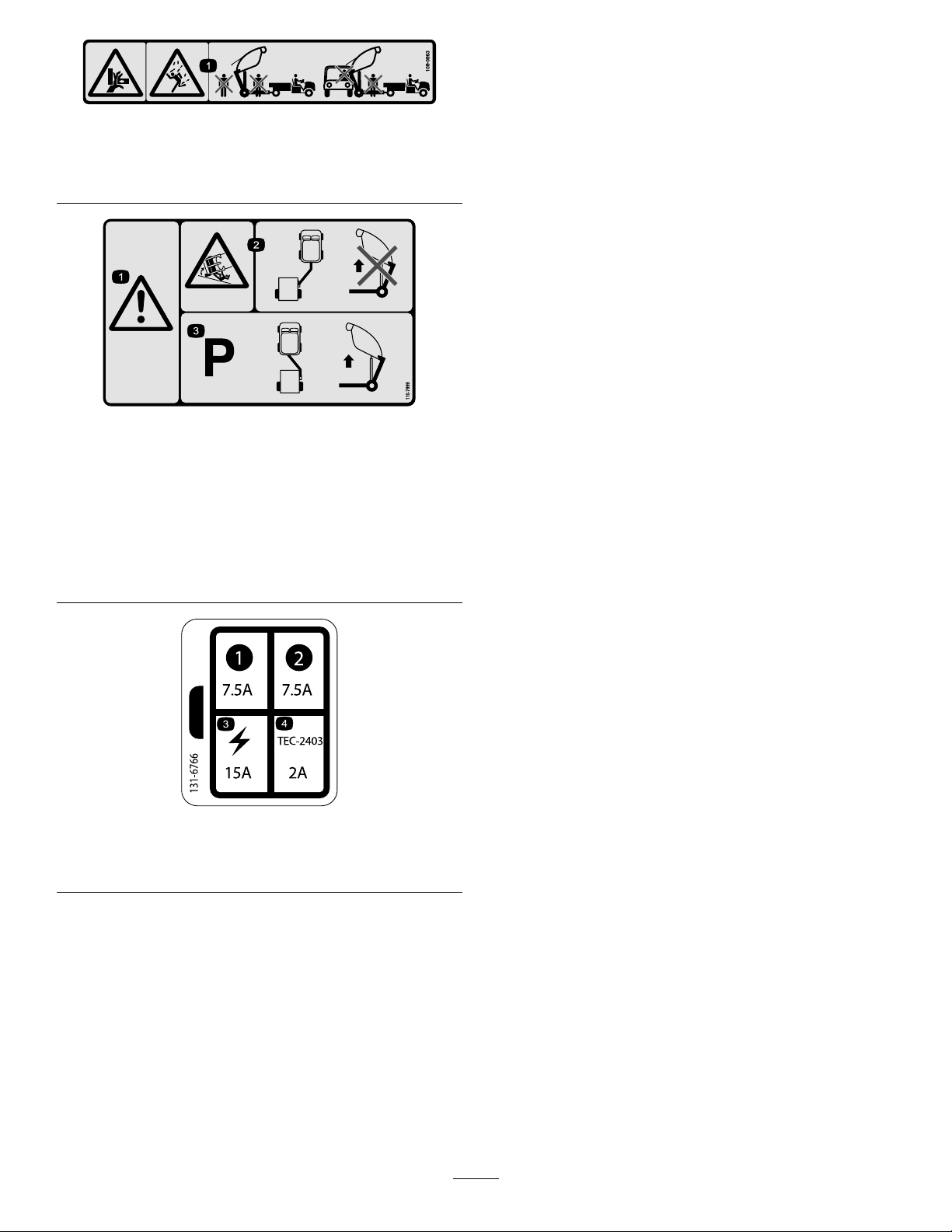
SafetyandInstructionalDecals.................................5
Setup............................................................................8
1RequirementsBeforeUsingtheVehicle....................9
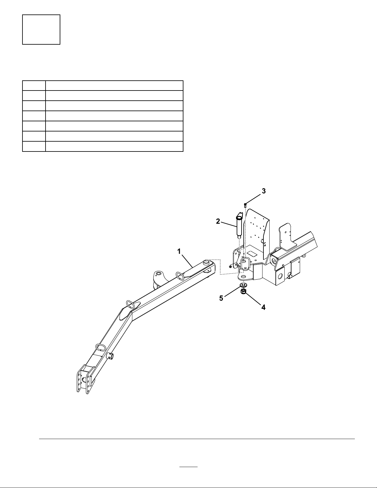
2RemovingtheHitchTongueandHydraulic
CylinderfromtheShippingPosition.......................9
3InstallingtheHitchTongue....................................9
4InstallingtheHydraulicCylinder............................11
5InstallingthePowerWiringHarness.......................12
6MountingtheSweepertotheTowVehicle................12
7RoutingandSecuringtheHydraulicHosesand
WiringHarness..................................................13
8ConnectingtheHydraulicHoses............................13
9ConnectingtheHarness........................................14
10MountingtheWindrowBlades.............................14
11AssemblingtheHandheldRemote........................16
ProductOverview.........................................................17
Controls...............................................................17
Specications........................................................18
DimensionsandWeights.........................................18
Attachments/Accessories........................................18
Operation....................................................................19
OperatingtheSweeper............................................19
AdjustingtheBrushHeight.....................................20
AdjustingtheRollerScraper.....................................21
AdjustingtheFrontFlapHeight..............................22
CheckingtheTirePressure......................................22
CheckingtheWheelLugNutTorque.........................22
ActivatingtheController.........................................22
UsingtheControllerTimeOut.................................23
UsingtheHopperSafetySupport.............................23
CheckingtheInterlockSystem.................................23
OperatingTips.......................................................23
DumpingtheHopper.............................................24
LoweringtheHopper..............................................24
InspectingandCleaningtheMachine........................25
TransportingtheSweeper........................................25
OperatingtheMachineinColdWeather.....................25
SwitchingtheSweeper-UpMode..............................25
Maintenance.................................................................26
RecommendedMaintenanceSchedule(s)......................26
DailyMaintenanceChecklist....................................27
Lubrication............................................................28
AssociatetheRemoteControlandtheBaseUnit
........................................................................29
ReplacingtheRemoteBatteries................................29
Storage........................................................................30
Troubleshooting...........................................................31
CheckingFaultCodes.............................................31
EnteringDiagnosticModeandCheckingthe
Codes................................................................32
ResettingtheFaultCodes........................................33
ExitingDiagnosticMode.........................................33
Safety
Hazardcontrolandaccidentpreventionaredependent
upontheawareness,concern,andpropertraining
ofthepersonnelinvolvedintheoperation,transport,
maintenance,andstorageofthemachine.Improper
useormaintenanceofthemachinecanresultininjury
ordeath.Toreducethepotentialforinjuryordeath,
complywiththefollowingsafetyinstructions.
ThefollowinginstructionsarefromANSIstandard
B71.4-2012.
SafeOperatingPractices
Supervisor'sResponsibilities
•Ensuretheoperatorsarethoroughlytrainedandfamiliar
withtheOperator'sManualandalldecalsonthemachine.
•Establishyourownspecialproceduresandworkrulesfor
unusualoperatingconditions(e.g.,slopestoosteepfor
machineoperation,adverseweatherconditions,etc.).
BeforeOperating
•Read,understandandfollowtheinstructionsinthe
Operator'sManualandonthemachinebeforestarting.
Becomefamiliarwithallcontrolsandknowhowto
stopquickly.Afreereplacementmanualisavailableby
contactingTorodirectlyatwww .Toro.com.
•Neverallowchildrentooperatethemachine.Neverallow
adultstooperatethemachinewithoutproperinstruction.
Onlytrainedoperatorswhohavereadthismanualshould
operatethismachine.
•Neveroperatethemachinewhileundertheinuenceof
drugsoralcohol.
•Becomefamiliarwiththecontrolsandknowhowtostop
thetowvehicleenginequickly.
•Keepallshields,safetydevices,anddecalsinplace.
Ifashield,safetydevice,ordecalbecomesdamaged,
malfunctioning,orillegible,repairorreplaceitbefore
operationiscommenced.Alsotightenloosenutsand
boltstoensuremachineisinsafeoperatingcondition.
•Alwayswearsubstantialshoes.Donotoperatemachine
whilewearingsandals,tennisshoes,orsneakersorwhen
barefoot.Donotwearloose-ttingclothingthatcould
getcaughtinmovingpartsandpossiblycauseinjury.
Wearingsafetyglasses,safetyshoes,longpants,anda
helmetisadvisableandrequiredbysomelocalordinances
andinsuranceregulations.
•Donotalterthisequipmentinanymannerwhichmay
causehazardousconditions.
•Safetyinterlockswitchesarefortheoperatorsprotection.
Disconnectedormalfunctioningsafetyinterlockswitches
couldallowthemachinetooperateinanunsafemanner
andmaycausepersonalinjury
–Donotdisconnectthesafetyinterlockswitches.
3

–Checktheoperationoftheswitchesdailytobesure
theinterlocksystemisoperatingcorrectly.
–Ifaswitchismalfunctioning,replaceitbefore
operatingthemachine.
WhileOperating
•Rotatingpartscancauseseriouspersonalinjury.Keep
handsandfeetawayfromsweeperreelwhilemachineis
running.Keephands,feet,hair,andclothingawayfrom
allmovingpartstopreventinjury.Neveroperatethe
machinewithcovers,shrouds,orguardsremoved.
•Don'ttakeaninjuryrisk!Whenapersonorpet
appearsunexpectedlyinornearthesweepingarea,stop
sweeping.Carelessoperation,combinedwithterrain
angles,ricochets,ormissingordamagedguards,canlead
tothrownobjectinjuries.Donotresumesweepinguntil
areaiscleared.
•Nevercarrypassengers.
•Alwayslooktotherearofmachinebeforebackingupand
assurenooneisbehindthemachine.
•Operatormustbeskilledandtrainedinhowtodriveon
hillsides.Failuretousecautiononslopesorhillsmay
causelossofcontrol,possiblyresultinginpersonalinjury
ordeath.
•WhenusingaWorkmanasatowvehicle,itis
recommendedtoput500poundsofweightintothe
vehiclebedwhenoperatingonanyslopes.
•Lightningcancausesevereinjuryordeath.Iflightning
isseenorthunderisheardinthearea,donotoperate
themachine;seekshelter.
•Tipovercancauseseriousinjuryordeath.
–Neveroperateonsteepslopes.
–Sweepslopesupanddown,neveracrosstheface.
–Whengoinguphillordownhill,donotstoporstart
suddenly.
–Stayalertforholesintheterrainorotherhidden
hazards.Toavoidtippingorlossofcontrol,donot
driveclosetoaditch,creek,ordropoff.
–Nevertransportthesweeperwhenthetransport
alarmisactivated.
–Nevertransportthesweeperwhenitisintheoffset
position.
–Ifenginestallsormachinelosesheadwayandcannot
makeittothetopofaslope,donotturnmachine
around.Alwaysbackslowlystraightdowntheslope.
•Usingthemachinedemandsattention.Failuretooperate
machinesafetymayresultinanaccident,tipoverofthe
machine,andpossibleseriousinjuryordeath.Drive
carefully.Topreventtippingorlossofcontrol:
–Operateonlyindaylightorwhenthereisgood
articiallight.
–Driveslowly.
–Watchforholesorotherhazards.
–Usecarewhenbackingmachine.
–Donotdriveclosetoasandtrap,ditch,tallcurb,
creek,orotherhazard.
–Reducespeedwhenmakingsharpturns.
–Avoidturningthesweeperonahillsideor
embankment.
–Avoidsuddenstopsandstarts.
–Donotgofromreversetoforwardorforwardto
reversewithoutrstcomingtoacompletestop.
–Donotattemptsharpturnsorabruptmaneuversor
otherunsafedrivingactionsthatmaycauselossof
control.
–Watchoutfortrafcwhennearorcrossingroads.
Alwaysyieldtheright-of-way.
WhileDumping
•Thesweepermustbeinthetransportposition(directly
behindtowvehicle)beforeactivatingdumpcycle.
•Dumpingdebriscancauseseriousinjury.Stayclearof
hopperwhilemachineisbackingupordumping.
•Underrarecircumstanceswet,compressedgrassclippings
maygenerateheat.Alwaysemptythehopperbefore
storingtheunit.
•Raisingandloweringofhopperdoorcouldcauseinjury
tobystandersorpets.Keepbystandersandpetsasafe
distancefromhopperwhenoperatingtodumpdebrisor
whenopeningandclosinghopperdoor.
•Toavoidtheriskofelectricalshock,dumphopperonlyin
areaclearofoverheadwiresandotherobstructions.
•Neverdumphopperonaslope.Alwaysdumphopper
onlevelground.
•Parkmachineonalevelsurface,emptyhopper,lower
hooperuntilrollerisonthegroundandblockwheels
beforeremovingsweeperfromtowvehicle.
Maintenance
•Hydraulicuidescapingunderpressurecanpenetrate
skinanddoseriousdamage.Keepbodyandhandsaway
frompinholeleaksornozzlesthatejecthighpressure
hydraulicuid.Usecardboardorpapertondhydraulic
leaks.Fluidaccidentallyinjectedintotheskinmustbe
surgicallyremovedwithinafewhoursbyadoctorfamiliar
withthisformofinjuryorgangrenemayresult.
•Performonlythosemaintenanceinstructionsdescribedin
thismanual.Ifmajorrepairsareeverneededorassistance
desired,contactanAuthorizedToroDistributor.
•Makesureallhydrauliclineconnectorsaretight,andall
hydraulichosesandlinesareingoodconditionbefore
applyingpressuretothesystem.
4

•Performingmaintenanceonmachinenotproperly
supportedwithjackstandsmaycausemachinetofalland
couldcauseinjury.
•Tobesureofoptimumperformanceandsafety,always
purchasegenuineTororeplacementpartsandaccessories.
Replacementpartsandaccessoriesmadebyother
manufacturerscouldbedangerous.Alteringthismachine
inanymannermayaffectthemachine'soperation,
performance,ordurability,oritsusemayresultininjury
ordeath.SuchusecouldvoidproductwarrantyofThe
ToroCompany.
SafetyandInstructionalDecals
Safetydecalsandinstructionsareeasilyvisibletotheoperatorandarelocatednearanyareaofpotential
danger.Replaceanydecalthatisdamagedorlost.
93-9899
93-9899
1.Crushinghazard—installthecylinderlock.
58-6520
1.Grease
108–0868
1.Warning—keephandsandfeetoutofthesweeperbrush.
2.Tippinghazard—donotoperatewiththesweeperinthe
raisedpositiononslopesgreaterthan5degrees.
108–0870
1.Entanglementhazard,belts—stayawayfrommovingparts,
keepallguardsandshieldsinplace;donotoperatewith
coversremoved.
108–0872
1.Crushinghazardofhand—keephandsawayfrompinch
points.
5

93-9852
1.Warning—readtheOperator’sManual.2.Crushinghazard—installthecylinderlock.
108–0862
1.Warning—readtheOperator'sManual,donotoperatethismachineunlessyouaretrained;keepbystandersasafedistancefrom
themachine.
2.Entanglementhazard,belts—stayawayfrommovingparts,keepallguardsandshieldsinplace;donotoperatewithcovers
removed.
108–0873
1.Thrownobjecthazard—keepbystandersasafedistance
away.
108–0865
1.Warning—keepbystandersasafedistancefromthe
machinewhendumpingsweeper.
108–0861
1.Warning—readtheOperator'sManual,donotoperatethismachineunlessyouaretrained.
2.Crushing/dismembermenthazardofbystanders—donotcarrypassengers.
3.Electricalshockhazard,overheadpowerlines—watchforoverheadpowerlines.
4.Lossofcontrolhazard—themaximumloadatthesweeperis1590kg(3500lb),atthehitchis114kg(250lb),donotdrive
downslopes.
5.Warning—keepspeedsbelow24kmh(15mph).
6.Storedenergyhazard,trailer—lowerthesweeper,placeitonblocksorjackstands,disconnectthesweeper,disconnectthe
hydraulicsandwiringharness;donotdrivethesweeperintheraisedposition.
6

108–0863
1.Crushinghazard,fallingobjecthazard—keepbystanders
andvehiclesasafedistancefromthemachinewhenthe
sweeperisraised.
110-7999
1.Warning3.Themachinemustbe
parkedwiththeattachment
inthetowpositionbefore
raisingthesweeperto
dump.
2.Tippinghazard—Whenthe
attachmentisinthesweep
positiondonotraisethe
attachmenttodump.
131-6766
1.7.5A3.Electricalaccessory—15A
2.7.5A4.TEC-2403—2A
7

Setup
LooseParts
Usethechartbelowtoverifythatallpartshavebeenshipped.
ProcedureDescriptionQty.Use
1Nopartsrequired–Requirementsbeforeusingthevehicle.
2Nopartsrequired–Removethetongueandhydraulic
cylinderfromtheshippingposition.
Hitchtongue1
Hitchpin1
Bolt(3/8x1-1/4inch)1
Nut(3/8-16)1
Largewasher1
Largenut1
3
Square-headsetscrew1
Installthehitchtongue
Rear-actuatortab1
Bolt(1/2x2inch)4
Flatwasher(.531x.063)8
Locknut(1/2inch)4
Bolt(3/8x1–1/4inch)2
Pinassembly2
4
Flangenut(3/8inch)2
Installthehydrauliccylinder.
Powerwiringharness1
5Cabletie2Installthepowerwiringharness.
Hitchpin1
6Hairpincotter1Mountthesweepertothetowvehicle.
7Cabletie8Routeandsecurethehydraulichoses
andwiringharness.
8Nopartsrequired–Connectthehydraulichoses.
9Nopartsrequired–Connecttheharness.
Blade-mountingassembly1
Bolt(7/16x3-3/4inch)1
Bolt(7/16x3-1/4inch)1
Smallwasher(1/2inch)4
Largewasher1
Spacer1
Locknut(7/16inch)2
Chain1
Bolt(3/8x1-1/4inch)1
Flangenut(3/8inch)1
10
Snaplink1
Mountthewindrowblades.
Handheldremote1
Battery(AAA)4
11Screws,small6
Assemblethehandheldremote.
8

MediaandAdditionalParts
DescriptionQty.Use
Operator'sManual1Readbeforeoperatingthesweeper
PartsCatalog1Usetoreferencepartnumbers
CECerticate1
RemoteControl1Usetooperatethesweeper
1
RequirementsBeforeUsing
theVehicle
NoPartsRequired
Procedure
•TheToroProSweepcanbetowedbymostutilitytractors
equippedwithhydraulicsproducing7to8GPM@2000
p.s.i.andotationtiresforoperationovergolfgreens.
Ensurethetractorhasadequatebrakesandadrawbar
hitchcapacitytohandlea3500lb.(1587kg.)trailer.
RefertothetowvehicleOperator'sManualfortowing
instructionsandprecautions.
•TheWorkmanvehiclemustbeequippedwiththe
High-FlowHydraulicsKit.Workmanvehicleswithserial
numberspriorto900000001,needtheHeavyDuty
Drawbar(Model44212or44213)installed.
Note:The4WDWorkmanmodelisthebestforhillyor
bermedapproachestogreens.
Important:ForoldermodelWorkmanvehicles,do
notattempttopullthesweeperwhenloadedwith
material,withthestandardWorkmanhitch.Itisonly
ratedto1500lbs.andmaybendordamagethecross
tubeaxlesupportorrearspringshackles.Alwaysuse
theH.D.DrawbarKitModel44212orH.D.Frame
DrawbarModel44213.
Important:Donotattempttowingaloadedsweeper
withalightutilityvehicleorrun-about.These
machinesdonothaveadequatebrakes,suspension,
orframestrengthtohandletheweightofthesweeper.
•Trailerbrakesarerecommendedwhenusingthesweeper
inhillyterrain.Whenfullyloaded,thesweepermayweigh
asmuchas1,588kg(3,500lb)(GVW).Thisweightisover
therecommendedtowingandbrakinglimitofmostutility
vehicles.Aspecialtrailerbrakekitisavailablefordirect
installationwiththeWorkmanvehicle.
Note:Thetrailerbrakekitcanbeadaptedtoother
vehicleswitha12voltbrakelightsource.
2
RemovingtheHitchTongue
andHydraulicCylinderfrom
theShippingPosition
NoPartsRequired
Procedure
Note:Have2peopleremovethehitchassembly.
1.Removethepinassembly,boltandnutsecuringthe
hydrauliccylinderandhosestothehitchtonguefor
shipping.Also,cutthecabletie.Carefullylowerthe
cylinderandhosesfromthetongue.Retainthepin
assemblyandfastenersforre-use.
2.Removethehairpincotterandhitchpinsecuringthe
hitchtonguetotheuppershippingbracket.Thehitch
tongueisveryheavy,usecautionwhenremovingthe
tonguefromtheshippingbrackets.
3.Pivotatthelowershippingpinandpivotthetounge
down.
4.Removethepinassembly,boltandnutsecuringthe
hitchtonguetothelowershippingbracket.
Note:Themachinewillshiftupwardatthelowerpin
shippingbracket.
5.Removethefastenerssecuringtheshippingbracketsto
thesweeper.Removeanddiscardtheshippingbrackets.
9

3
InstallingtheHitchTongue
Partsneededforthisprocedure:
1Hitchtongue
1Hitchpin
1Bolt(3/8x1-1/4inch)
1Nut(3/8-16)
1Largewasher
1Largenut
1Square-headsetscrew
Procedure
Note:Thisprocedurerequires2people.
1.Inserttherearendofthehitchtonguebetweenthe
mountingplatesonthesweeperwhilealigningthe
mountingholes(Figure3).
Note:Thehoseguidesaretobepositionedontop
ofhitchtongue.
2.Insertthehitchpinthroughthemountingplatesand
thehitchtongue(Figure3).
3.Securethetopofthehitchpintothemountingplate
withabolt(3/8x1-1/4inch)andalocknut(3/8inch)
(Figure3).
4.Securethebottomofthehitchpinwithalargewasher,
largenutandsquare-headsetscrew(Figure3).
Figure3
1.Hitchtongue4.Largenutandsquare-headsetscrew
2.Hitchpin5.Largewasher
3.Bolt(3/8x1–1/4inch)andlocknut(3/8inch)
10

5.Loosenthejamnutssecuringtheproximityswitchto
theframeandlowertheswitchuntilitis2.6to4.0mm
(0.10to0.16inch)fromthesensingplateonthehitch
tongue(Figure4).Tightenthejamnutstosecurethe
adjustment.
G01 1587
1
2
3
4
5
2
Figure4
1.Proximityswitch4.Sensingplate
2.Jamnut5.Hitchtongue
3.2.6to4.0mm(0.10to0.16
inch)
4
InstallingtheHydraulic
Cylinder
Partsneededforthisprocedure:
1Rear-actuatortab
4Bolt(1/2x2inch)
8Flatwasher(.531x.063)
4Locknut(1/2inch)
2Bolt(3/8x1–1/4inch)
2Pinassembly
2Flangenut(3/8inch)
Procedure
1.Mounttherearactuatortabtothesweeperframewith
4bolts(1/2x2inch),8atwashers(.531x.063),and
4locknuts(1/2inch).Positionthecomponentsas
showninFigure5.
Figure5
1.Rearactuatortab2.Sweeperframe
2.Secureeachendofthehydrauliccylindertoanactuator
tabwithapinassembly,abolt(3/8x1-1/4inch),and
aangenut(3/8inch)Figure6).
Note:Makesurethattherodend(workingend)of
thecylinderisattachedtothefrontactuatortab.
Figure6
1.Frontactuatortab3.Hydrauliccylinder
2.Rearactuatortab4.Pinassembly
11

5
InstallingthePowerWiring
Harness
Partsneededforthisprocedure:
1Powerwiringharness
2Cabletie
Procedure
1.Disconnectthebatteryfromthevehicle.
2.Attachthepowerwiringharnessringterminaltothe
groundboltnearthevehiclefuseblock.
3.Plugtheharnesswireintotheredwireonthebackof
thefuseblock.
Note:IftheWorkmanvehicledoesnothaveanopen
fuseslot,obtainandinstallaToroaccessoryfuseblock,
Partno.92–2641.
4.Routethewiringharnessalongsidethemainvehicle
wiringharnesstotherearofthevehicle(Figure7).
Figure7
1.Powerwiringharness
5.Securethewiringharnesstothevehicleinseveral
placeswithcableties.Keeptheharnessawayfromany
hotorrotatingcomponents.
Note:Theharnessisequippedwithaconnectorfor
theoptionalbrakecontrolkit.
6.Connectthevehiclebattery.
6
MountingtheSweepertothe
TowVehicle
Partsneededforthisprocedure:
1Hitchpin
1Hairpincotter
Procedure
Toensureproperdebrispickup,makesurethatthesweeper
frameisparallelwiththeground.
1.Positionthesweeperonaat,levelsurface.
2.Backthetowvehicleuptothesweeper.
3.Removethespringpin,rotatethejackdownandinstall
thespringpin(Figure8).
Figure8
1.Jack2.Springpin
4.Jackupthehitchtongueuntilitisparalleltotheground.
5.Adjustthesweeperhitchclevistothesamelevelastow
vehiclehitchasfollows:
•Removetheboltsandlocknutssecuringthehitch
clevis(Figure9)tothehitchtongue.
12

Figure9
1.Hitchpin3.Hairpincotter
2.Clevis
•Raiseorlowerthehitchclevistotheposition
approximatelylevelwiththetowvehiclehitch.
•Securetheclevistothehitchwiththeboltsand
locknutspreviouslyremoved.
Note:Makesurethatthesweeperisparallelwith
theground.
6.Connectthesweeperclevishitchtothetowvehicle
hitchwiththehitchpinandhairpincotter.
7.Removethespringpin,rotatethejackanduptothe
storagepositionandinstallthespringpin.
7
RoutingandSecuringthe
HydraulicHosesandWiring
Harness
Partsneededforthisprocedure:
8Cabletie
Procedure
1.Routethehydraulichosesandwiringharnessthrough
thehoseguidestothefrontofthehitchtongue(Figure
10).
Figure10
1.Hydraulichosesandwiring
harness
2.Hoseguide
2.Securethehydraulichosesandwiringharnessasshown
inFigure11andFigure12.
Figure11
FrontView
1.Cabletie(6)
Figure12
RearView
1.Cabletie(2)
13

8
ConnectingtheHydraulic
Hoses
NoPartsRequired
Procedure
Connectthehydraulichosesfromthesweepertothequick
couplersonthetowvehicle(Figure13).
g03051 1
Figure13
1.Hydraulichoses2.Harness'
Important:Makesurethatthebrushrotatesinthe
properdirection(whenviewedfromthemotorend,
thebrushshouldrotateclockwise).Ifthebrushis
rotatingcounterclockwise,reversethehydraulichose
connections.
Note:Markthehigh-pressurehosewithacabletieto
identifythecorrecthoseinstallation(Figure14).
Figure14
1.Highpressurehose2.Cabletie
9
ConnectingtheHarness
NoPartsRequired
Procedure
Connecttheharnessfromthesweepertothepowerharness
onthetowvehicle(Figure13).
Note:Ensuretheharnesscannotgetpinchedinthehitch
andensuretheharnessisnotontopoforaroundthehitch
pin.
10
MountingtheWindrowBlades
Partsneededforthisprocedure:
1Blade-mountingassembly
1Bolt(7/16x3-3/4inch)
1Bolt(7/16x3-1/4inch)
4Smallwasher(1/2inch)
1Largewasher
1Spacer
2Locknut(7/16inch)
1Chain
1Bolt(3/8x1-1/4inch)
1Flangenut(3/8inch)
1Snaplink
Procedure
1.Securetheblademountingassemblytotheleftend
ofthesweeperframewithabolt(7/16x3-1/4inch)
bolt,2smallwashers,alargewasher,andalocknut
(7/16inch).
Note:PositioncomponentsasshowninFigure15.
2.Securethewindrowbladetothemountingassembly
withabolt(7/16x3-1/4inch),2atwashers,aspacer
andalocknut(7/16inch).Assemblethecomponents
asshowninFigure15.
Note:Positionthelongerendofthebladeawayfrom
thesweeper.
3.Securethechaintotheblademountingassemblywith
abolt(3/8x1-1/4inch)andaangenut(3/8inch)
(Figure15).
14

4.Securetheotherendofthechaintotheslotinthe
framewiththesnaplink(Figure15).
Note:Thereshouldbesomeslackinthechainwhen
connected.
5.Greasethettingontheblademountingassemblyand
onthewindrowbladehubwithNo.2lithiumgrease.
Note:Whenthewindrowisnotrequired,unhookthe
chainfromthesnaplink,pivotthewindrowassembly
upward,andhookthechainattheraisedlevel.
Figure15
1.Bolt(7/16x3-3/4inches)8.Windrowblade
2.Smallwasher(1/2inch)9.Spacer
3.Sweeperframe10.Bolt(3/8x1-1/4inches)
4.Largewasher11.Chain
5.Blade-mountassembly12.Flangenut(3/8inch)
6.Locknut(7/16inch)13.Snaplink
7.Bolt(7/16x3-1/4inches)
15

11
AssemblingtheHandheld
Remote
Partsneededforthisprocedure:
1Handheldremote
4Battery(AAA)
6Screws,small
Procedure
1.Removetherubberbandssecuringtheremotehalves
together,andremovethebackcover.
2.Plugeachbatteryintoaterminalcradleobserving
properpolarity(Figure16).
Note:Ifthebatteriesareimproperlyinstalled,theunit
willnotbedamaged,butitwillfailtooperate.The
cradleisembossedwithpolaritymarkingsforeach
terminal.
Figure16
1.Screw4.Steelgasket
2.Cover5.Batteries
3.Seal6.Handheldremote
3.Ensurethatthesteelgasketandrubbersealareseated
inthechannelintheremoteandsetthebackcover
inplace(Figure16).
4.Securethecoverwith6screws(Figure16)andtorque
themto1.5to1.7N-m(13to15in-lb).
Note:Donotovertightenthescrews.
16

ProductOverview
Controls
HopperDumpButton
Todumpthehopper,pressthehopperdumpbutton2times
(Figure17).
Important:Thesweepermustbedirectlybehindthe
towvehicleandintransportheightbeforethedump
sequencecanbeactivated.
Figure17
1.LEDlight5.Stop
2.Off-setleft6.Sweeperup
3.Sweeperdown7.Off-setright
4.Hopperdump
SweeperDownButton
Tolowerthehopper,pressthesweeperdownbutton(Figure
17).Thehoppercanbeloweredwhenitisatanyofthe
followingpositions:
•Hopperdumpheight
•Transportheight
•Turnaroundheight
Note:Whenloweringthehopperfromthedump
position,thelowerhopperfunctioncanbestoppedatany
timebyreleasingthesweeper-downbutton.
Note:Withthesweeperinthetransportorturn-around
positions,thelowerhopperfunctioncanbestoppedat
anytimebypressingthesweeperupbutton.
SweeperUpButton—StandardMode
Toraisethesweeperinstandardmode,pressthesweeper-up
button.Thehopperwillstopatthepre-denedheight
(Figure17).
•Transportheight(homeposition)is13–1/4to15–1/4
inches.
•Turnaroundheight(off-setposition)is8–1/2to10–1/2
inches.
SweeperUpButton—OptionalMode
Thismodeallowstheoperatortoadjustthesweepertoany
desiredheightanditstopsatthepre-denedheights.
Note:RefertoSwitchingtheSweeper-UpMode(page25)to
switchtotheoptionalmode.
Toraisethesweeperinoptionalmode,pressandholdthe
sweeper-upbuttonuntilthehopperreachesthedesiredheight
orstopsatthepre-denedheight(Figure17).
•Transportheight(homeposition)is13–1/4to15–1/4
inches.
•Turnaroundheight(off-setposition)is8–1/2to10–1/2
inches.
Off-SetLeftButton
Tooff-setthesweepertotheleft,pressandholdtheoff-set
leftbutton(Figure17).Releasingthebuttonwillstopthe
movementtotheleft.
Off-SetRightButton
Tooff-setthesweepertotheright,pressandholdtheoff-set
rightbutton(Figure17).Releasingthebuttonwillstopthe
movementtotheright.
StopButton
Pressingthestopbuttonwilldisableanyactivefunction.
Note:Thereisapproximatelya3seconddelay.
17

DiagnosticLight
Thediagnosticlight(Figure18)islocatedonthefrontcover
andindicatesmachinefaultcodes.Afteryouturnthekey
totheRUNposition,thediagnosticlightwillilluminatefor
5seconds,turnofffor5seconds,andthenbeginashing
3timesaseconduntilyoupushabuttononthehandheld
remote.Ifthelightturnsonfor5secondsandthenstarts
blinking10timesasecond(withorwithouta5secondpause)
thereisafaultwiththemachine;refertoCheckingFault
Codes(page31).
Note:Thediagnosticlightilluminateswhenabuttonis
pushedonthehandheldremote.
Note:Ifyouhaveabuttondepressedonthehandheld
remotewhenyoustartthemachine,thelightwillnotash3
timesasecondafteritturnsofffor5seconds.
Figure18
1.Diagnosticlight
Specications
Note:Specicationsanddesignaresubjecttochange
withoutnotice.
DimensionsandWeights
Width221cm(87inches)
Height202cm(79-1/2inches)
Dumpheightclearance173cm(68inches)
LengthHopperlowered-
173cm(68inches)
Hopperraised-229-249
cm(90-98inches)
Emptyweight680kg(1500lb)
Grossvehicleweight(GVW)1588kg(3500lb)
Attachments/Accessories
AselectionofToroapprovedattachmentsandaccessoriesis
availableforusewiththemachinetoenhanceandexpand
itscapabilities.ContactyourAuthorizedServiceDealeror
Distributororgotowww .Toro.comforalistofallapproved
attachmentsandaccessories.
18

Operation
Note:Determinetheleftandrightsidesofthemachinefromthenormaloperatingposition.
OperatingtheSweeper
Theprimaryfunctionofthemachineistosweepupdebris
fromlargeturfareas.
Thesweeperisoperatedbyusingtheremotecontrol.Referto
Controls(page17)fortheproperuseofthecontrolbuttons.
Positonthesweeperinthefollowingheightswhen
transportingandturning:
•Transportheight(homeposition)is33.7to38.7cm
(13–1/4to15–1/4inches).
•Turnaroundheight(offsetposition)is21.6to26.7cm
(8–1/2to10–1/2inches).
WARNING
Rotatingpartscancauseseriouspersonalinjury.
•Keephandsandfeetawayfromthesweeperreel
whilethemachineisrunning.
•Keephands,feet,hair,andclothingawayfrom
allmovingpartstopreventinjury.
•Neveroperatethemachinewithcovers,shrouds,
orguardsremoved.
19

AdjustingtheBrushHeight
Adjustthesweepersothebrushtipsslightlytouchthesurfacebutdonotpenetratetheturf.Ifthebrushtipsdopenetrate
theturf,improperdebrispickupcouldresult.
Refertothechartsbelowfortherecommendedsweepersettings.
ConditionRoller/BrushAdjustmentFrontFlapAdjustmentNotes
Greens/TeeBoxes2to4notchesfrombottom6to13mm(1/4to1/2inch)
fromground
Brushshouldbeslightly
engagedintheturf
Fairways3to5notchesfrombottom13to25mm(1/2to1inch)from
ground
Brushshouldbeengagedinto
thetop1/3ofthegrassheight
Sportselds5to7notchesfrombottom25to76mm(1to3inches)
fromground
Brushshouldbeengagedinto
thetop1/3ofthegrassheight
Leaves5to9notchesfrombottomRemovefrontpanelBrushshouldbeengagedinto
thetop1/3ofthegrassheight
ABC
OpenSlotsTabUpT abDown
5.5006.000
05.6256.125
5.7506.250
15.8756.375
6.0006.500
26.1256.625
6.2506.750
36.3756.875
6.5007.000
46.6257.125
6.7507.250
56.8757.375
7.0007.500
67.1257.625
7.2507.750
77.3757.875
7.5008.000
87.6258.125
7.7508.250
97.8758.375
8.0008.500
108.1258.625
8.2508.750
118.3758.875
8.5009.000
128.6259.125
8.7509.250
138.8759.375
20
Table of contents
Other Toro Blower manuals

Toro
Toro Power Sweep 51586 User manual

Toro
Toro Flex-Force Power System 51825T User manual

Toro
Toro 51549-79000001 User manual

Toro
Toro Pro Force Debris Blower User manual

Toro
Toro 51618 User manual

Toro
Toro Super 325 User manual

Toro
Toro 30393 User manual

Toro
Toro QuieTech 51589 User manual

Toro
Toro 51599 User manual

Toro
Toro Air Rake User manual

Toro
Toro Pro Force 44553 User manual

Toro
Toro Pro Force 44547 User manual

Toro
Toro 51619 User manual

Toro
Toro Versa Vac 07053 User manual

Toro
Toro 51668 User manual

Toro
Toro Groundsmaster 4000-D User manual

Toro
Toro ProForce Debris User manual

Toro
Toro 51617 User manual

Toro
Toro Flex-Force Power System 51824 User manual

Toro
Toro ProForce 44538 User manual