Toro Pro Sweep 07066 User manual

(Model 07066)
Part No. 10179SL
Service Manual
Pro Sweep
Preface
The purpose of this publication is to provide the service
technician with information for troubleshooting, testing
andrepairofmajor systemsandcomponentsonthePro
Sweep (Model 07066).
REFER TO THE OPERATOR’S MANUAL FOR OPER-
ATING, MAINTENANCE AND ADJUSTMENT
INSTRUCTIONS. SpaceisprovidedinChapter2ofthis
book to insert the Operator’s Manual and Parts Catalog
for your machine. Additional copies of the Operator’s
Manual and Parts Catalog are available on the internet
at www.Toro.com.
TheToroCompany reservestherighttochangeproduct
specifications or this publication without notice.
This safety symbol means DANGER, WARNING,
or CAUTION, PERSONAL SAFETY INSTRUC-
TION. When you see this symbol, carefully read
the instructions that follow. Failure to obey the
instructions may result in personal injury.
NOTE: ANOTE will give general information about the
correct operation, maintenance, service, testing or re-
pair of the machine.
IMPORTANT: The IMPORTANT notice will give im-
portantinstructionswhichmustbefollowedtopre-
vent damage to systems or components on the
machine.
EThe Toro Company -- 2011

Pro Sweep
This page is intentionally blank.

Pro Sweep
Table Of Contents
Chapter 1 -- Safety
Safety Instructions 1 -- 2..........................
Jacking Instructions 1 -- 4.........................
Securing Pro Sweep to Tow Vehicle 1 -- 5...........
Safety and Instruction Decals 1 -- 5................
Chapter 2 -- Product Records and Maintenance
Product Records 2 -- 1...........................
Maintenance 2 -- 1...............................
Equivalents and Conversions 2 -- 2................
Torque Specifications 2 -- 3.......................
Chapter 3 -- Hydraulic System
General Information 3 -- 2........................
Hydraulic Schematic 3 -- 7........................
Hydraulic Flow Diagrams 3 -- 8....................
Troubleshooting 3 -- 16...........................
Service and Repairs 3 -- 22.......................
PARKER TORQLINKTM SERVICE PROCEDURE
Chapter 4 -- Electrical System
General Information 4 -- 2........................
Special Tools 4 -- 2..............................
Troubleshooting 4 -- 3............................
Safety Interlock System 4 -- 6.....................
Adjustments 4 -- 7...............................
Component Testing 4 -- 8.........................
Service and Repairs 4 -- 18.......................
Chapter 5 -- Chassis
Specifications 5 -- 2..............................
General Information 5 -- 3........................
Service and Repairs 5 -- 4........................
Chapter 6 -- Electrical Diagrams
Electrical Schematic 6 -- 3........................
Circuit Drawings 6 -- 4............................
Wire Harness Drawings 6 -- 11....................
SafetyProduct Records
and Maintenance
Hydraulic
System
Electrical
Chassis
Electrical SystemDiagrams

Pro Sweep
This page is intentionally blank.

Pro Sweep Page 1 -- 1 Safety
Chapter 1
Safety
Table of Contents
SAFETY INSTRUCTIONS 2......................
Before Operating 2............................
While Operating 2.............................
Maintenance and Service 3....................
JACKING INSTRUCTIONS 4.....................
SECURING PRO SWEEP TO TOW VEHICLE 5....
SAFETY AND INSTRUCTION DECALS 5..........
Safety

Pro Sweep
Page 1 -- 2
Safety
Safety Instructions
The Pro Sweep is designed and tested to offer safe ser-
vice when operated and maintained properly. Although
hazard control and accident prevention partially are de-
pendent upon the design and configuration of the ma-
chine, these factors are also dependent upon the
awareness, concern and proper training of the person-
nel involved in the operation, transport, maintenance
and storage of the machine. Improper use or mainte-
nanceof themachinecanresult ininjuryordeath. Tore-
duce the potential for injury or death, comply with the
following safety instructions.
WARNING
To reduce the potential for injury or death,
comply with thefollowing safetyinstructions.
Before Operating
1. Read and understand the contents of the Operator’s
Manual before operating the machine. Become familiar
with the controls and know how to stop the sweeper
quickly. Additional copies of the Operator’s Manual are
available on the internet at www.Toro.com.
2. Keep all shields, safety devices and decals in place.
If a shield, safety device or decal is defective, illegible
or damaged, repair or replace it before operating the
machine.
3. Make sure that any loose nuts, bolts or screws are
tightenedtoensurethat themachineisinsafeoperating
condition.
4. Make sure that the tow vehicle is carefully selected
to assure the best performance and safe operation of
the Pro Sweep.
5. Assuresweeper interlocksystemfunctionscorrectly
so sweeper brush does not rotate unless sweeper is
positioned below the transport position.
6. Make sure that operator is familiar with tow vehicle
operation.
While Operating
1. Operator should be in the operators position when
operating the tow vehicle and sweeper. Stay away from
the sweeper when the brush is engaged.
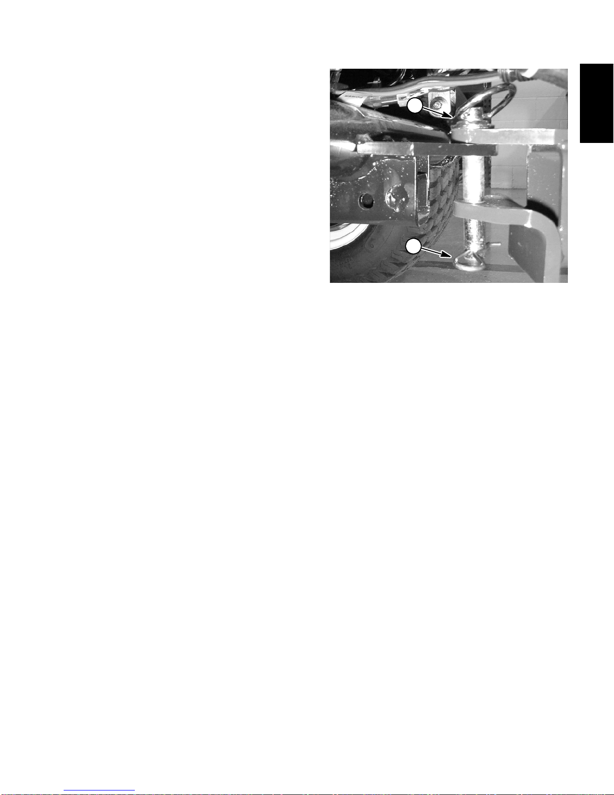
2. Make sure that hitch pin is properly positioned in tow
vehicle and sweeper. Hitch pin should be secured with
hairpin clip.
3. Donotruntowvehicleengineinaconfinedareawith-
out adequateventilation. Exhaust fumes arehazardous
and could possibly be deadly.
4. Do not touch tow vehicle engine, muffler or exhaust
pipe while engine is running or soon after it is stopped.
These areas could be hot enough to cause burns.
5. If abnormal vibration is detected, stop tow vehicle
and sweeper immediately and determine source of
vibration. Correct problems before resuming the use of
sweeper.
6. While operating, the Pro Sweep may exceed noise
levels of 85dB(A) at the operator position. Hearing
protection is recommended for prolonged exposure to
reduce the potential of permanent hearing damage.
7. Before leaving the operator’s position of the tow ve-
hicle:
A. Stop sweeper brush by shutting off vehicle hy-
draulic flow to the sweeper.
B. Make sure that dump hopper is lowered.
C. Ensurethat vehicletractionlever isin neutral,ap-
ply parking brake, stop engine and remove key from
ignition switch.
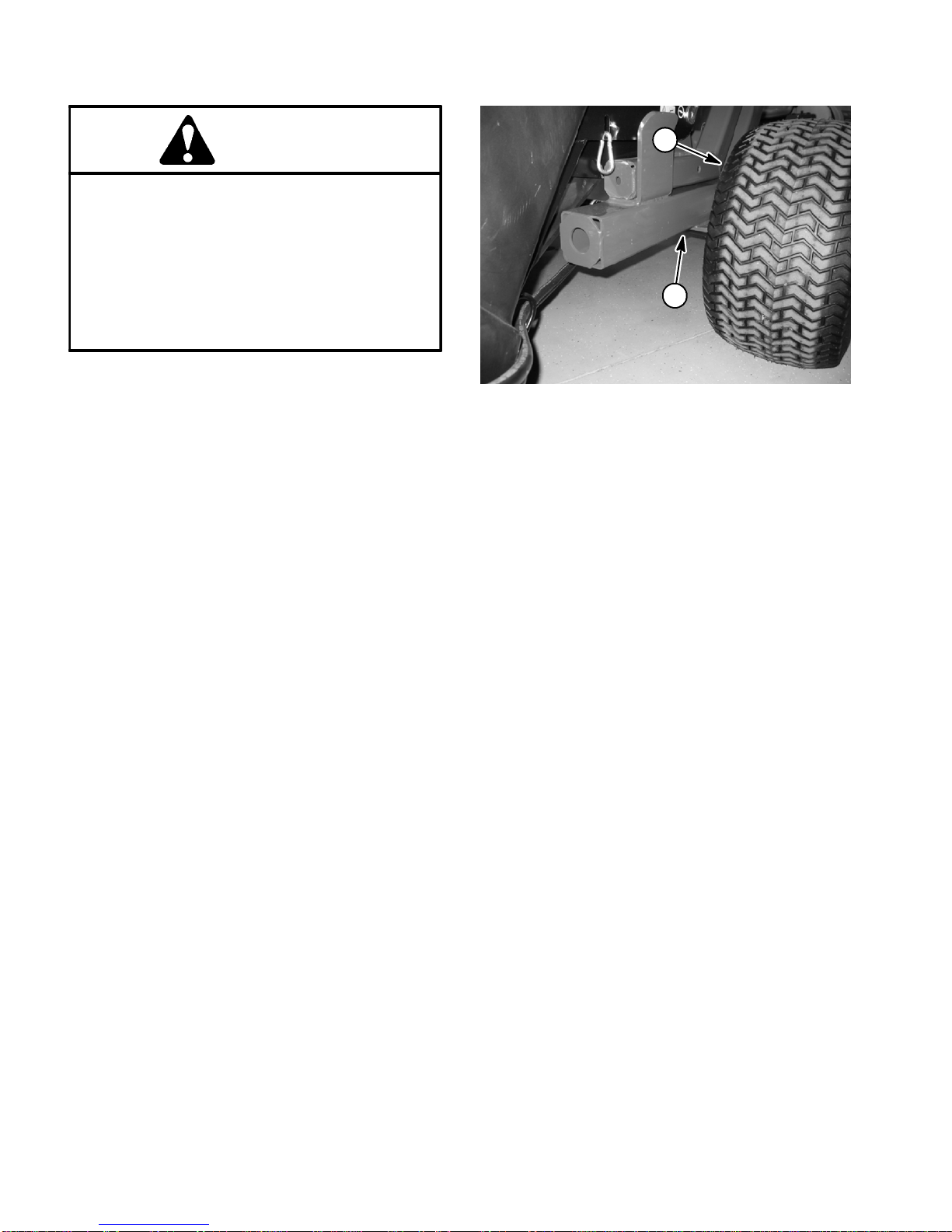
8. Position sweeper on level surface, empty hopper
and chock sweeper wheels before disconnecting Pro
Sweep from tow vehicle.

Pro Sweep Page 1 -- 3 Safety
Maintenance and Service
1. Before servicing or making adjustments, empty Pro
Sweep hopper and position sweeper on a level surface.
Chock sweeper wheels to prevent it from moving. If
sweeper is attached to tow vehicle, apply tow vehicle
parking brake, stop engine and remove key from the
ignition switch.
2. Make sure machine is in safe operating condition by
keeping all nuts, bolts and screws tight.
3. Make sure all hydraulic line connectors are tight and
all hydraulic hoses and lines are in good condition be-
fore applying pressure to the hydraulic system.
4. Keepbodyandhandsawayfrompinholeleaksinhy-
draulic lines that eject high pressure hydraulic fluid. Use
cardboard or paper to find hydraulic leaks. Hydraulic
fluid escaping under pressure can penetrate skin and
cause injury. Hydraulic fluid accidentally injected into
the skin must be surgically removed within a few hours
by a doctor familiar with this form of injury or gangrene
may result.
5. Before disconnecting any hydraulic component or
performing any work on the hydraulic system, all pres-
sure in system must be relieved. See Relieving Hydrau-
lic System Pressure in the General Information section
of Chapter 3 -- Hydraulic System.
6. If hopper is to be raised, make sure that sweeper is
not placed in the offset position.
7. If hopper is raised, install hopper safety support on
lift cylinder to ensure that unexpected shifting of sweep-
er frame does not occur.
8. Disconnect electrical power harness from tow ve-
hicle before servicing the sweeper.
9. If major repairs are ever needed or assistance is de-
sired, contact an Authorized Toro Distributor.
10.At the time of manufacture, the machine conformed
to all applicable safety standards. To assure optimum
performance and continued safety certification of the
machine, use genuine Toro replacement parts and ac-
cessories. Replacement parts and accessories made
by other manufacturers may result in non-conformance
with the safety standards, and the warranty may be
voided.
11.When changing tires or performing other service,
use correct hoists and jacks. Make sure machine is
parked on a solid level surface such as a concrete floor
with the hopper empty and lowered. Have sweeper at-
tached to towing vehicle, apply vehicle parking brake,
stop engineandremovekeyfromtheignitionswitch.Al-
ways chock or block wheels. Use appropriate jack
stands to support the raised machine. If the machine is
not properly supported by appropriate jack stands, the
machine may move or fall, which may result in personal
injury (see Jacking Instructions in this chapter).
Safety

Pro Sweep
Page 1 -- 4
Safety
Jacking Instructions
CAUTION
When changing tires or performing other ser-
vice, use correct hoists and jacks to support
sweeper. Make sure machine is parked on a sol-
id level surfacesuchasaconcrete floor.Always
chock or block wheels. Use appropriate jack
standstosupporttheraisedmachine.If thema-
chine is not properly supported by appropriate
jack stands, the machine may move or fall,
which may result in personal injury.
1. Position sweeper on a level surface with dump hop-
per empty and lowered. Have sweeper attached to tow-
ing vehicle, apply vehicle parking brake, stop engine
and remove key from the ignition switch. Chock sweep-
er wheels to prevent it from moving.
2. Position jack securely under the main sweeper
frame (Fig. 1). Do not use the axle as a jacking point.
3. Carefully jack machine off the ground.
4. Position appropriate jack stands under the main
frame to support the sweeper.
1. Wheel 2. Frame jacking point
Figure 1
2
1

Pro Sweep Page 1 -- 5 Safety
Securing Pro Sweep to Tow Vehicle
While operating or servicing the Pro Sweep, make sure
that hitch pin is properly positioned in tow vehicle hitch
and sweeper tongue. Hitch pin should be secured with
hairpin clip (Fig. 2).
1. Hitch pin 2. Hairpin clip
Figure 2
2
1
Safety and Instruction Decals
Numerous safety and instruction decals are affixed to
the Pro Sweep. If any decal becomes illegible or dam-
aged,installanewdecal.Partnumbersforreplacement
decals are listed in your Parts Catalog. Order replace-
ment decals from your Authorized Toro Distributor.
Safety

Pro Sweep
Page 1 -- 6
Safety
This page is intentionally blank.

Pro Sweep Page 2 -- 1 Product Records and Maintenance
Chapter 2
Product Records and Maintenance
Table of Contents
PRODUCT RECORDS 1.........................
MAINTENANCE 1...............................
EQUIVALENTS AND CONVERSIONS 2...........
Decimal and Millimeter Equivalents 2............
U.S. to Metric Conversions 2...................
TORQUE SPECIFICATIONS 3....................
Fastener Identification 3.......................
Using a Torque Wrench with an Offset Wrench 3..
Standard Torque for Dry, Zinc Plated and
Steel Fasteners (Inch Series) 4...............
Standard Torque for Dry, Zinc Plated and
Steel Fasteners (Metric Fasteners) 5...........
Other Torque Specifications 6..................
Conversion Factors 6..........................
Product Records
InsertOperator’sManualandPartsCatalogforyourPro
Sweep at the end of this chapter. Additionally, if any op-
tional equipment or accessories have been installed to
your machine, insert the Installation Instructions, Oper-
ator’s Manuals and Parts Catalogs for those options at
the end of this chapter.
Maintenance
Maintenanceproceduresandrecommendedservicein-
tervals for the Pro Sweep are covered in the Operator’s
Manual.Refertothatpublicationwhenperformingregu-
lar equipment maintenance.
Product Records
and Maintenance

0.09375
Pro Sweep
Page 2 -- 2
Product Records and Maintenance
Equivalents and Conversions

Pro Sweep Page 2 -- 3 Product Records and Maintenance
Torque Specifications
Recommended fastener torque values are listed in the
followingtables.Forcriticalapplications,as determined
byToro,eithertherecommendedtorqueoratorquethat
is unique to the application is clearly identified and spe-
cified in this Service Manual.
These Torque Specifications for the installation and
tightening of fasteners shall apply toall fasteners which
donothavea specific requirement identified in this Ser-
vice Manual. The following factors shall be considered
when applying torque: cleanliness of the fastener, use
of a thread sealant (e.g. Loctite), degree of lubrication
onthefastener,presenceofaprevailingtorquefeature,
hardnessofthesurfaceunderneaththefastener’shead
or similar condition which affects the installation.
Asnotedinthefollowingtables,torquevaluesshouldbe
reduced by 25% for lubricated fasteners to achieve
the similar stress as a dry fastener. Torque values may
also have to be reduced when the fastener is threaded
into aluminum or brass. The specific torque value
should be determined based on the aluminum or brass
material strength, fastener size, length of thread en-
gagement, etc.
The standard method of verifying torque shall be per-
formed by marking a line on the fastener (head or nut)
and mating part, then back off fastener 1/4 of a turn.
Measurethetorquerequiredtotightenthefasteneruntil
the lines match up.
Fastener Identification
Figure 1
Grade 1 Grade 5 Grade 8
Inch Series Bolts and Screws Figure 2
Class 8.8 Class 10.9
Metric Bolts and Screws
Using a Torque Wrench with an Offset Wrench
Useofanoffsetwrench(e.g.crowfootwrench)willaffect
torquewrenchcalibrationdueto the effectivechangeof
torquewrenchlength.Whenusingatorquewrenchwith
an offset wrench, multiply the listed torque recommen-
dation by the calculated torque conversion factor (Fig.
3) to determine proper tightening torque. Tightening
torque when using a torque wrench with an offset
wrench will be lower than the listed torque recommen-
dation.
Example: The measured effective length of the torque
wrench (distance from the center of the handle to the
center of the square drive) is 18”.
Themeasuredeffectivelengthofthetorquewrenchwith
the offset wrench installed (distance from the center of
the handle to the center of the offset wrench) is 19”.
The calculated torque conversion factor for this torque
wrenchwiththisoffsetwrenchwouldbe18/19 = 0.947.
If the listed torque recommendation for a fastener is
from 76 to 94 ft--lb, the proper torque when using this
torque wrench with an offset wrench would be from 72
to 89 ft--lb.
Figure 3
(effective length of
torque wrench)
TORQUE CONVERSION FACTOR = A / B
A
B
(effective length of torque
Torque wrenchOffset wrench
wrench + offset wrench)
Product Records
and Maintenance

Pro Sweep
Page 2 -- 4
Product Records and Maintenance
Standard Torque for Dry, Zinc Plated and Steel Fasteners (Inch Series)
Thread Size Grade 1, 5 &
8withThin
Height Nuts
SAE Grade 1 Bolts, Screws, Studs &
Sems with Regular Height Nuts
(SAE J995 Grade 2 or Stronger Nuts)
SAE Grade 5 Bolts, Screws, Studs &
Sems with Regular Height Nuts
(SAE J995 Grade 2 or Stronger Nuts)
SAE Grade 8 Bolts, Screws, Studs &
Sems with Regular Height Nuts
(SAE J995 Grade 5 or Stronger Nuts)
in--lb in--lb N--cm in--lb N--cm in--lb N--cm
# 6 -- 32 UNC
1
0
+
2
1
3
+
2
1
4
7
+
2
3
15 + 2169 + 23 23 + 3262 + 34
# 6 -- 40 UNF 10 + 213 + 2147 + 23 17 + 2192 + 23 25 + 3282 + 34
# 8 -- 32 UNC
1
3
+
2
2
5
+
5
2
8
2
+
3
0
29 + 3328 + 34 41 + 5463 + 56
# 8 -- 36 UNF 13 + 225 + 5282 + 30 31 + 4350 + 45 43 + 5486 + 56
#10--24UNC
1
8
+
2
3
0
+
5
3
3
9
+
5
6
42 + 5475 + 56 60 + 6678 + 68
#10--32UNF 18 + 230 + 5339 + 56 48 + 5542 + 56 68 + 7768 + 79
1/4 -- 20 UNC 48 + 753 + 7599 + 79 100 + 10 1130 + 113 140 + 15 1582 + 169
1/4 -- 28 UNF 53 + 765 + 10 734 + 113 115 + 12 1299 + 136 160 + 17 1808 + 192
5/16 -- 18 UNC 115 + 15 105 + 15 1186 + 169 200 + 25 2260 + 282 300 + 30 3390 + 339
5/16 -- 24 UNF 138 + 17 128 + 17 1446 + 192 225 + 25 2542 + 282 325 + 33 3672 + 373
ft--lb ft--lb N--m ft--lb N--m ft--lb N--m
3/8 -- 16 UNC 16 + 216 + 222 + 330 + 341 + 443 + 558 + 7
3/8 -- 24 UNF 17 + 218 + 224 + 335 + 447 + 550 + 668 + 8
7/16 -- 14 UNC 27 + 327 + 337 + 450 + 568 + 770 + 795 + 9
7/16 -- 20 UNF 29 + 329 + 339 + 455 + 675 + 877 + 8104 + 11
1/2 -- 13 UNC 30 + 348 + 765 + 975 + 8102 + 11 105 + 11 142 + 15
1/2 -- 20 UNF 32 + 453 + 772 + 985 + 9115 + 12 120 + 12 163 + 16
5/8 -- 11 UNC 65 + 10 88 + 12 119 + 16 150 + 15 203 + 20 210 + 21 285 + 28
5/8 -- 18 UNF 75 + 10 95 + 15 129 + 20 170 + 18 230 + 24 240 + 24 325 + 33
3/4 -- 10 UNC 93 + 12 140 + 20 190 + 27 265 + 27 359 + 37 375 + 38 508 + 52
3/4 -- 16 UNF 115 + 15 165 + 25 224 + 34 300 + 30 407 + 41 420 + 43 569 + 58
7/8 -- 9 UNC 140 + 20 225 + 25 305 + 34 430 + 45 583 + 61 600 + 60 813 + 81
7/8 -- 14 UNF 155 + 25 260 + 30 353 + 41 475 + 48 644 + 65 667 + 66 904 + 89
NOTE: Reduce torque values listed in the table above
by 25% for lubricated fasteners. Lubricated fasteners
are defined as threads coated with a lubricant such as
engine oil or thread sealant such as Loctite.
NOTE: Torque values may have to be reduced when
installing fasteners into threaded aluminum or brass.
The specific torque value should be determined based
on the fastener size, the aluminum or base material
strength, length of thread engagement, etc.
NOTE: The nominal torque values listed above for
Grade 5 and 8 fasteners are based on 75% of the mini-
mumproofloadspecified in SAE J429. The tolerance is
approximately + 10% of the nominal torque value. Thin
height nuts include jam nuts.

Pro Sweep Page 2 -- 5 Product Records and Maintenance
Standard Torque for Dry, Zinc Plated and Steel Fasteners (Metric Fasteners)
T
h
r
e
a
d
S
i
z
e
Class 8.8 Bolts, Screws and Studs with
R
e
g
u
l
a
r
H
e
i
g
h
t
N
u
t
s
Class 10.9 Bolts, Screws and Studs with
R
e
g
u
l
a
r
H
e
i
g
h
t
N
u
t
s
Thread Size Regular Height Nuts
(Class 8 or Stronger Nuts) Regular Height Nuts
(Class 10 or Stronger Nuts)
M5 X 0.8 57 + 6in--lb 644 + 68 N--cm 78 + 8in--lb 881 + 90 N--cm
M6 X 1.0 96 + 10 in--lb 1085 + 113 N--cm 133 + 14 in--lb 1503 + 158 N--cm
M8 X 1.25 19 + 2ft--lb 26 + 3N--m 28 + 3ft--lb 38 + 4N--m
M10 X 1.5 38 + 4ft--lb 52 + 5N--m 54 + 6ft--lb 73 + 8N--m
M12 X 1.75 66 + 7ft--lb 90 + 10 N--m 93 + 10 ft--lb 126 + 14 N--m
M16 X 2.0 166 + 17 ft--lb 225 + 23 N--m 229 + 23 ft--lb 310 + 31 N--m
M20 X 2.5 325 + 33 ft--lb 440 + 45 N--m 450 + 46 ft--lb 610 + 62 N--m
NOTE: Reduce torque values listed in the table above
by 25% for lubricated fasteners. Lubricated fasteners
are defined as threads coated with a lubricant such as
engine oil or thread sealant such as Loctite.
NOTE: Torque values may have to be reduced when
installing fasteners into threaded aluminum or brass.
The specific torque value should be determined based
on the fastener size, the aluminum or base material
strength, length of thread engagement, etc.
NOTE: The nominal torque values listed above are
based on 75% of the minimum proof load specified in
SAEJ1199.Thetoleranceisapproximately+10%ofthe
nominal torque value.
Product Records
and Maintenance

Pro Sweep
Page 2 -- 6
Product Records and Maintenance
Other Torque Specifications
SAE Grade 8 Steel Set Screws
T
h
r
e
a
d
S
i
z
e
Recommended Torque
Thread Size Square Head Hex Socket
1/4 -- 20 UNC 140 + 20 in--lb 73 + 12 in--lb
5/16 -- 18 UNC 215 + 35 in--lb 145 + 20 in--lb
3/8 -- 16 UNC 35 + 10 ft--lb 18 + 3ft--lb
1/2 -- 13 UNC 75 + 15 ft--lb 50 + 10 ft--lb
Thread Cutting Screws
(Zinc Plated Steel)
Type 1, Type 23 or Type F
Thread Size Baseline Torque*
No. 6 -- 32 UNC 20 + 5in--lb
No. 8 -- 32 UNC 30 + 5in--lb
No. 10 -- 24 UNC 38 + 7in--lb
1/4 -- 20 UNC 85 + 15 in--lb
5/16 -- 18 UNC 110 + 20 in--lb
3/8 -- 16 UNC 200 + 100 in--lb
Wheel Bolts and Lug Nuts
Thread Size Recommended Torque**
7/16 -- 20 UNF
Grade 5 65 + 10 ft--lb 88 + 14 N--m
1/2 -- 20 UNF
Grade 5 80 + 10 ft--lb 108 + 14 N--m
M12 X 1.25
Class 8.8 80 + 10 ft--lb 108 + 14 N--m
M12 X 1.5
Class 8.8 80 + 10 ft--lb 108 + 14 N--m
** For steel wheels and non--lubricated fasteners.
Thread Cutting Screws
(Zinc Plated Steel)
Thread
S
i
z
e
Threads per Inch
B
a
s
e
l
i
n
e
T
o
r
q
u
e
*
Size Type A Type B Baseline Torque
*
No. 6 18 20 20 + 5in--lb
No. 8 15 18 30 + 5in--lb
No. 10 12 16 38 + 7in--lb
No. 12 11 14 85 + 15 in--lb
*Holesize,materialstrength,materialthickness&finish
must be considered when determining specific torque
values. All torque values are based on non--lubricated
fasteners.
Conversion Factors
in--lb X 11.2985 = N--cm N--cm X 0.08851 = in--lb
ft--lb X 1.3558 = N--m N--m X 0.7376 = ft--lb

Pro Sweep Hydraulic SystemPage 3 -- 1
Chapter 3
Hydraulic System
Table of Contents
GENERAL INFORMATION 2.....................
Operator’s Manual 2..........................
Hydraulic Hoses 2............................
Hydraulic Hose and Tube Installation 3..........
Hydraulic Fitting Installation 4...................
Relieving Hydraulic System Pressure 6..........
Securing Pro Sweep to Tow Vehicle 6...........
HYDRAULIC SCHEMATIC 7.....................
HYDRAULIC FLOW DIAGRAMS 8................
Brush Circuit 8...............................
Sweeper Raise/Hopper Dump Circuits 10........
Sweeper Lower Circuits 12.....................
Sweeper Offset Circuits 14.....................
TROUBLESHOOTING 16........................
SERVICE AND REPAIRS 22.....................
General Precautions for Removing and Installing
Hydraulic System Components 22.............
Check Hydraulic Lines and Hoses 23............
Brush Motor 24...............................
Brush Motor Service 26........................
Hydraulic Control Manifold 28...................
Hydraulic Control Manifold Service 30...........
Lift Cylinder 32...............................
Lift Cylinder Service 34........................
Offset Cylinder 36.............................
Offset Cylinder Service 38......................
PARKER TORQLINKTM SERVICE PROCEDURE
Hydraulic
System

Pro SweepHydraulic System Page 3 -- 2
General Information
Operator’s Manual
The Operator’s Manual provides information regarding
the operation, general maintenance and maintenance
intervalsforyourProSweepmachine.Refertothatpub-
lication for additional information when servicing the
machine.
Hydraulic Hoses
Hydraulichosesaresubjecttoextremeconditionssuch
aspressuredifferentialsduring operationandexposure
to weather, sun, chemicals, very warm storage condi-
tionsormishandlingduringoperationandmaintenance.
These conditions can cause hose damage and deterio-
ration. Some hoses are more susceptible to these
conditions than others. Inspect all machine hydraulic
hoses frequently for signs of deterioration or damage:
Hard, cracked, cut, abraded, charred, leaking or
otherwise damaged hose.
Kinked, crushed, flattened or twisted hose.
Blistered, soft, degraded or loose hose cover.
Cracked, damaged or badly corroded hose fittings.
When replacing a hydraulic hose, be sure that the hose
is straight (not twisted) before tightening the fittings.
This can be done by observing the imprint (layline) on
the hose. Use two wrenches when tightening a hose;
hold the hose straight with one wrench and tighten the
hose swivel nut onto the fitting with the second wrench
(see Hydraulic Hose and Tube Installation in this sec-
tion). If the hose has an elbow at one end, tighten the
swivel nut on that end before tightening the nut on the
straight end of the hose.
For additional hydraulic hose information, refer to Toro
Service Training Book, Hydraulic Hose Servicing (Part
Number 94813SL).
WARNING
Beforedisconnectingor performingany work on
hydraulic system, relieve all pressure in system
(seeRelievingHydraulic SystemPressure in this
section).
Keepbodyandhandsawayfrompinholeleaksor
nozzles that eject hydraulic fluid under high
pressure. Use paper or cardboard, not hands, to
search for leaks. Hydraulic fluid escaping under
pressure can have sufficient force to penetrate
the skin and cause serious injury. If fluid is in-
jected into the skin, it must be surgically re-
moved within a few hours by a doctor familiar
withthistypeofinjury.Gangrenemayresultfrom
such an injury.

Pro Sweep Hydraulic SystemPage 3 -- 3
Hydraulic Hose and Tube Installation (O--Ring Face Seal Fitting)
1. Makesurethreadsandsealingsurfacesofthehose/
tube and the fittingare free of burrs, nicks, scratches or
any foreign material.
2. Asapreventativemeasureagainstleakage,itisrec-
ommended that the face seal O--ring be replaced any
time the connection is opened. Make sure the O--ring is
installedandproperlyseatedinthefittinggroove.Lightly
lubricate the O--ring with clean hydraulic oil.
3. Place the hose/tube against the fitting body so that
theflatfaceofthehose/tubesleevefullycontactstheO--
ring in the fitting.
4. Thread the swivel nut onto the fitting by hand. While
holding the hose/tube with a wrench, use a torque
wrench to tighten the swivel nut to the recommended
installation torque shown in Figure 3. This tightening
process will require the use of an offset wrench (e.g.
crowfoot wrench). Use of an offset wrench will affect
torque wrench calibration due to the effective length
change of the torque wrench. Tightening torque when
usingatorquewrenchwithanoffsetwrenchwillbelower
than the listed installation torque (see Using a Torque
Wrench with an Offset Wrench in the Torque Specifica-
tionssectionofChapter2 -- ProductRecords andMain-
tenance).
5. If a torque wrench is not available or if space at the
swivelnutpreventsuseofatorquewrench,analternate
method of assembly is the Flats From Wrench Resist-
ance (F.F.W.R.) method (Fig. 2).
A. Usingawrench,tightentheswivelnutontothefit-
tinguntillightwrenchresistanceisreached(approxi-
mately 30 in--lb).
B. Mark the swivel nut and fitting body. Hold the
hose/tube with a wrench to prevent it from turning.
C. Useasecondwrenchtotightenthenuttothecor-
rect Flats From Wrench Resistance (F.F.W.R.). The
markingsonthenutandfittingbodywillverifythatthe
connection has been properly tightened.
Size F.F.W.R.
4 (1/4 in. nominal hose or tubing) 1/2 to 3/4
6 (3/8 in.) 1/2 to 3/4
8 (1/2 in.) 1/2 to 3/4
10 (5/8 in.) 1/2 to 3/4
12 (3/4 in.) 1/3 to 1/2
16 (1 in.) 1/3 to 1/2
Figure 1
O--ring Fitting Body
Swivel Nut
Tube or Hose
Figure 2
Final
AT WRENCH RESISTANCE
Position
Mark Nut
and Fitting
Initial
Position
Extend Line
AFTER TIGHTENING
Body
Fitting Dash Size Hose/Tube Side Thread Size Installation Torque
49/16 -- 18 18to22ft--lb(25to29N--m)
611/16 -- 16 27to33ft--lb(37to44N--m)
813/16 -- 16 37to47ft--lb(51to63N--m)
10 1--14 60 to 74 ft--lb (82 to 100 N--m)
12 13/16--12 85 to 105 ft--lb (116 to 142 N--m)
16 17/16--12 110 to 136 ft--lb (150 to 184 N--m)
20 1 11/16 -- 12 140 to 172 ft--lb (190 to 233 N--m)
Figure 3
Hydraulic
System

Pro SweepHydraulic System Page 3 -- 4
Hydraulic Fitting Installation (SAE Straight Thread O--Ring Fitting into Component Port)
Non--Adjustable Fitting (Fig. 4)
1. Make sure all threads and sealing surfaces of fitting
and component port are free of burrs, nicks, scratches
or any foreign material.
2. Asapreventativemeasureagainstleakage,itisrec-
ommended that the O--ring be replaced any time the
connection is opened.
3. Lightly lubricate the O--ring with clean hydraulic oil.
Fittingthreadsshouldbecleanwithnolubricantapplied.
IMPORTANT: Before installing fitting into port, de-
termine port material. If fitting is to be installed into
an aluminum port, installation torque is reduced.
4. Install the fitting into the port. Then, use a torque
wrench and socket to tighten the fitting to the recom-
mended installation torque shown in Figure 5.
NOTE: Use of an offset wrench(e.g. crowfoot wrench)
will affect torque wrench calibration due to the effective
length change of the torque wrench. Tightening torque
when using a torque wrench with an offset wrench will
be less than the recommended installation torque. See
Using a Torque Wrench with an Offset Wrench in the
Torque Specifications section of Chapter 2 -- Product
RecordsandMaintenancetodeterminenecessarycon-
version information.
5. If a torque wrench is not available, or if space at the
portpreventsuseofatorquewrench,analternatemeth-
od of assembly is the Flats From Finger Tight (F.F.F.T.)
method.
A. Install the fitting into the port and tighten it down
full length until finger tight.
B. If port material is steel, tighten the fitting to the
listed F.F.F.T. If port material is aluminum, tighten fit-
ting to 60% of listed F.F.F.T.
Size F.F.F.T.
4 (1/4 in. nominal hose or tubing) 1.00 + 0.25
6(3/8in.) 1.50+0.25
8(1/2in.) 1.50+0.25
10 (5/8 in.) 1.50 + 0.25
12 (3/4 in.) 1.50 + 0.25
16 (1 in.) 1.50 + 0.25
Figure 4
O--ring
Fitting
Fitting
Dash Size Fitting Port Side
Thread Size Installation Torque Into
Steel Port Installation Torque Into
Aluminum Port
47/16 -- 20 15to19ft--lb(21to25N--m) 9to11ft--lb(13to15N--m)
51/2 -- 20 18to22ft--lb(25to29N--m) 11to15ft--lb(15to20N--m)
69/16 -- 18 34to42ft--lb(47to56N--m) 20to26ft--lb(28to35N--m)
83/4 -- 16 58to72ft--lb(79to97N--m) 35to43ft--lb(48to58N--m)
10 7/8 -- 14 99 to 121 ft--lb (135 to 164 N--m) 60 to 74 ft--lb (82 to 100 N--m)
12 11/16--12 134 to 164 ft--lb (182 to 222 N--m) 81 to 99 ft--lb (110 to 134 N--m)
14 13/16--12 160 to 196 ft--lb (217 to 265 N--m) 96 to 118 ft--lb (131 to 160 N--m)
16 15/16--12 202 to 248 ft--lb (274 to 336 N--m) 121 to 149 ft--lb (165 to 202 N--m)
20 15/8--12 247 to 303 ft--lb (335 to 410 N--m) 149 to 183 ft--lb (202 to 248 N--m)
Figure 5
Table of contents
Other Toro Blower manuals

Toro
Toro 51544 User manual

Toro
Toro POWERVAC 51985 User manual

Toro
Toro 51581 User manual

Toro
Toro Flex-Force Power System 51825T User manual

Toro
Toro Pro Force User manual

Toro
Toro Flex-Force Power System 51825T User manual

Toro
Toro 51593 User manual

Toro
Toro Power Sweep 51586 User manual

Toro
Toro Flex-Force Power System 51820 User manual

Toro
Toro Flex-Force Power System 51825T User manual

Toro
Toro 08759 User manual

Toro
Toro QUIETECH 51566 User manual

Toro
Toro RAKE-O-VAC 07050 User manual

Toro
Toro 51619 User manual

Toro
Toro 51821 User manual

Toro
Toro ProForce 44538 User manual

Toro
Toro Power Plex 51690 User manual

Toro
Toro 30823 User manual

Toro
Toro Pro Force 44553 User manual

Toro
Toro Power Plex 51134 User manual