Toro TX 1000 Compact Tool Carrier User manual

FormNo.3423-965RevA
TX1000CompactToolCarrier
ModelNo.22327—SerialNo.402000000andUp
ModelNo.22327G—SerialNo.402800000andUp
ModelNo.22327HD—SerialNo.402000000andUp
ModelNo.22328—SerialNo.403330000andUp
ModelNo.22328HD—SerialNo.403100000andUp
Registeratwww.Toro.com.
OriginalInstructions(EN)*3423-965*A

ThisproductcomplieswithallrelevantEuropean
directives;fordetails,pleaseseetheseparateproduct
specicDeclarationofConformity(DOC)sheet.
ItisaviolationofCaliforniaPublicResourceCode
Section4442or4443touseoroperatetheengineon
anyforest-covered,brush-covered,orgrass-covered
landunlesstheengineisequippedwithaspark
arrester,asdenedinSection4442,maintainedin
effectiveworkingorderortheengineisconstructed,
equipped,andmaintainedforthepreventionofre.
Theenclosedengineowner'smanualissupplied
forinformationregardingtheUSEnvironmental
ProtectionAgency(EPA)andtheCaliforniaEmission
ControlRegulationofemissionsystems,maintenance,
andwarranty.Replacementsmaybeorderedthrough
theenginemanufacturer.
WARNING
CALIFORNIA
Proposition65Warning
Dieselengineexhaustandsomeofits
constituentsareknowntotheStateof
Californiatocausecancer,birthdefects,
andotherreproductiveharm.
Batteryposts,terminals,andrelated
accessoriescontainleadandlead
compounds,chemicalsknownto
theStateofCaliforniatocause
cancerandreproductiveharm.Wash
handsafterhandling.
Useofthisproductmaycauseexposure
tochemicalsknowntotheStateof
Californiatocausecancer,birthdefects,
orotherreproductiveharm.
Introduction
Thismachineisacompacttoolcarrierintendedfor
useinvariousearthandmaterialsmovingactivitiesfor
landscapingandconstructionwork.Itisdesignedto
operateawidevarietyofattachmentseachofwhich
performaspecializedfunction.
Readthisinformationcarefullytolearnhowtooperate
andmaintainyourproductproperlyandtoavoid
injuryandproductdamage.Youareresponsiblefor
operatingtheproductproperlyandsafely.
YoumaycontactT orodirectlyatwww.T oro.com
forproductsafetyandoperationtrainingmaterials,
accessoryinformation,helpndingadealer,orto
registeryourproduct.
Wheneveryouneedservice,genuineToroparts,or
additionalinformation,contactanAuthorizedService
DealerorToroCustomerServiceandhavethemodel
andserialnumbersofyourproductready.Figure1
identiesthelocationofthemodelandserialnumbers
ontheproduct.Writethenumbersinthespace
provided.
Important:Withyourmobiledevice,youcan
scantheQRcodeontheserialnumberdecal(if
equipped)toaccesswarranty,parts,andother
productinformation.
g239557
Figure1
1.Modelandserialnumberlocation
ModelNo.
SerialNo.
Thismanualidentiespotentialhazardsandhas
safetymessagesidentiedbythesafety-alertsymbol
(Figure2),whichsignalsahazardthatmaycause
seriousinjuryordeathifyoudonotfollowthe
recommendedprecautions.
g000502
Figure2
Safety-alertsymbol
Thismanualuses2wordstohighlightinformation.
Importantcallsattentiontospecialmechanical
©2018—TheToro®Company
8111LyndaleAvenueSouth
Bloomington,MN554202
Contactusatwww.Toro.com.
PrintedintheUSA
AllRightsReserved

informationandNoteemphasizesgeneralinformation
worthyofspecialattention.
Contents
Safety.......................................................................4
GeneralSafety...................................................4
SafetyandInstructionalDecals..........................5
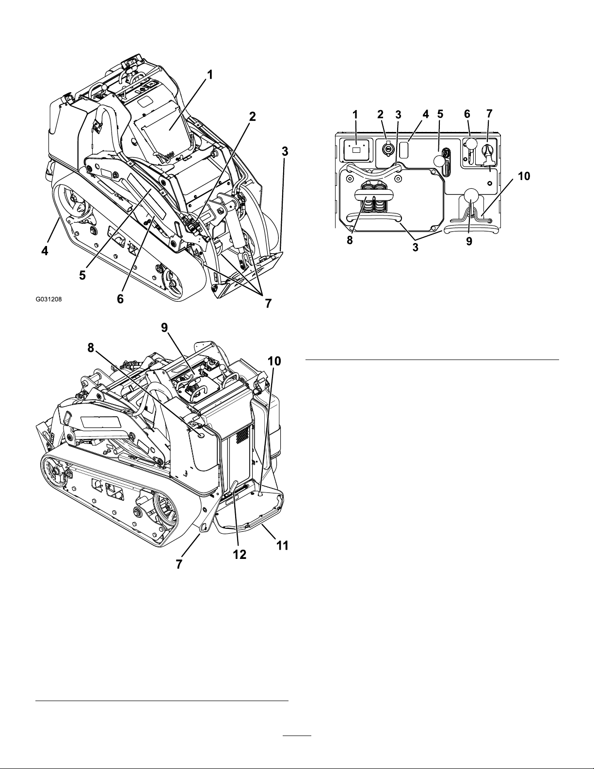
ProductOverview...................................................10
Controls...........................................................10
MessageDisplay...........................................14
Specications..................................................15
Attachments/Accessories.................................15
BeforeOperation.................................................15
BeforeOperationSafety...................................15
AddingFuel......................................................16
PerformingDailyMaintenance..........................16
DuringOperation.................................................17
DuringOperationSafety...................................17
StartingtheEngine...........................................18
DrivingtheMachine..........................................18
ShuttingOfftheEngine.....................................19
UsingAttachments...........................................19
AfterOperation....................................................21
AfterOperationSafety......................................21
MovingaNon-FunctioningMachine..................21
TransportingtheMachine.................................21
LiftingtheMachine...........................................23
Maintenance...........................................................24
RecommendedMaintenanceSchedule(s)...........24
Pre-MaintenanceProcedures..............................25
MaintenanceSafety..........................................25
UsingtheCylinderLocks..................................25
AccessingInternalComponents.......................26
Lubrication..........................................................28
GreasingtheMachine.......................................28
EngineMaintenance...........................................29
EngineSafety...................................................29
ServicingtheAirCleaner..................................29
ServicingtheEngineOil....................................30
FuelSystemMaintenance...................................32
DrainingtheFuelFilter/WaterSeparator...........32
ReplacingtheFuelFilterCanisterand
In-LineFilter..................................................32
CheckingtheFuelLinesand
Connections..................................................33
BleedingtheFuelSystem.................................33
DrainingtheFuelTank(s)..................................33
ElectricalSystemMaintenance...........................34
ElectricalSystemSafety...................................34
ServicingtheBattery.........................................34
ServicingtheFuses..........................................38
DriveSystemMaintenance..................................38
ServicingtheTracks.........................................38
CoolingSystemMaintenance..............................43
CoolingSystemSafety.....................................43
ServicingtheCoolingSystem...........................43
BrakeMaintenance.............................................44
TestingtheParkingBrake.................................44
ControlsSystemMaintenance.............................45
AdjustingtheControls.......................................45
HydraulicSystemMaintenance...........................45
HydraulicSystemSafety...................................45
HydraulicFluidSpecications...........................45
CheckingtheHydraulic-FluidLevel...................46
ReplacingtheHydraulicFilter...........................46
ChangingtheHydraulicFluid............................47
Cleaning..............................................................48
RemovingDebris..............................................48
CleaningtheChassis........................................48
Storage...................................................................49
StorageSafety..................................................49
Storage.............................................................49
Troubleshooting......................................................50
Schematics.............................................................54
3

Safety
DANGER
Theremaybeburiedutilitylinesinthework
area.Diggingintothemmaycauseashock
oranexplosion.
Havethepropertyorworkareamarkedfor
buriedlinesanddonotdiginmarkedareas.
Contactyourlocalmarkingserviceorutility
companytohavethepropertymarked(for
example,intheUS,call811orinAustralia,
call1100forthenationwidemarkingservice).
GeneralSafety
Alwaysfollowallsafetyinstructionstoavoidserious
injuryordeath.Usingthisproductforpurposesother
thanitsintendedusecouldprovedangeroustoyou
andbystanders.
•Donotcarryaloadwiththearmsraised;always
carryloadsclosetotheground.
•Slopesareamajorfactorrelatedtoloss-of-control
andtip-overaccidents,whichcanresultinsevere
injuryordeath.Operatingthemachineonany
slopeoruneventerrainrequiresextracaution.
•Operatethemachineupanddownslopeswith
theheavyendofthemachineuphillandtheload
closetotheground.Weightdistributionchanges
withattachments.Anemptybucketmakesthe
rearofthemachinetheheavyend,andafull
bucketmakesthefrontofthemachinetheheavy
end.Mostotherattachmentsmakethefrontofthe
machinetheheavyend.
•Havethepropertyorworkareamarkedforburied
linesandotherobjects,anddonotdiginmarked
areas.
•ReadandunderstandthecontentofthisOperator’s
Manualbeforestartingtheengine.
•Useyourfullattentionwhileoperatingthe
machine.Donotengageinanyactivitythat
causesdistractions;otherwise,injuryorproperty
damagemayoccur.
•Neverallowchildrenoruntrainedpeopleto
operatethemachine.
•Keepyourhandsandfeetawayfromthemoving
componentsandattachments.
•Donotoperatethemachinewithouttheguards
andothersafetyprotectivedevicesinplaceand
workingonthemachine.
•Keepbystandersandpetsasafedistanceaway
fromthemachine.
•Stopthemachine,shutofftheengine,andremove
thekeybeforeservicing,fueling,orunclogging
themachine.
Improperlyusingormaintainingthismachinecan
resultininjury.Toreducethepotentialforinjury,
complywiththesesafetyinstructionsandalways
payattentiontothesafety-alertsymbol,which
meansCaution,Warning,orDanger—personalsafety
instruction.Failuretocomplywiththeseinstructions
mayresultinpersonalinjuryordeath.
Youcanndadditionalsafetyinformationwhere
neededthroughoutthismanual.
4

SafetyandInstructionalDecals
Safetydecalsandinstructionsareeasilyvisibletotheoperatorandarelocatednearanyarea
ofpotentialdanger.Replaceanydecalthatisdamagedormissing.
decalbatterysymbols
BatterySymbols
Someorallofthesesymbolsareonyourbattery.
1.Explosionhazard6.Keepbystandersasafe
distanceawayfromthe
battery.
2.Nore,opename,or
smoking
7.Weareyeprotection;
explosivegasescan
causeblindnessandother
injuries.
3.Causticliquid/chemical
burnhazard
8.Batteryacidcancause
blindnessorsevereburns.
4.Weareyeprotection.9.Flusheyesimmediately
withwaterandgetmedical
helpfast.
5.ReadtheOperator's
Manual.
10.Containslead;donot
discard
decal93-6681
93-6681
1.Cutting/dismembermenthazard,fan—stayawayfrom
movingparts.
decal93-7814
93-7814
1.Entanglementhazard,belt—stayawayfrommovingparts.
decal93-9084
93-9084
1.Liftpoint/Tie-downpoint
decal115-2047
115-2047
1.Warning—donottouchthehotsurface.
decal115-4855
115-4855
1.Hotsurface/burnhazard—wearprotectivegloveswhen
handlingthehydrauliccouplersandreadtheOperator's
Manualforinformationonhandlinghydrauliccomponents.
decal115-4858
115-4858
1.Crushinghazardofhandsorfeet—installthecylinderlock.
decal115-4865
115-4865
1.Enginecoolant2.ReadtheOperator's
Manual.
5

decal117-3276
117-3276
1.Enginecoolantunder
pressure
3.Warning—donottouchthe
hotsurface.
2.Explosionhazard—read
theOperator'sManual.
4.Warning—readthe
Operator'sManual.
decal120-0625
120-0625
1.Pinchpoint,hand—keephandsaway.
decal130-2836
130-2836
1.Crushinghazard;cuttinghazard—keepawayfromthe
attachmentandtheliftarm.
decal130-7637
130-7637
1.Blinking
light—engine-coolant
temperature
6.Enginestart
2.Steadylight—engine-oil
pressure
7.Parkingbrakedisengaged
3.Blinkinglight—glowplug8.Tractionneutral
4.Steadylight—battery
warning
9.Auxiliaryleverneutral
5.Hourmeter
decal131-0709
131-0709
1.Parkingbrake—engage2.Parkingbrake—disengage
decal131-0711
131-0711
1.Crushinghazard—keepawayfrompinchpointsand
actuatingparts.
6

decal131-8026
131-8026
1.Battery
power—disconnect
3.Off
2.On4.ReadtheOperator's
Manual.
decal136-5750
136-5750
1.ReadtheOperator's
Manual.
2.Tensionblockguide
decal137-9030
137-9030
1.Engine—stop3.Engine—start
2.Engine—run
decal133-8056
133-8056
7

decal131-0597
131-0597
decal131-0708
131-0708
1.Moveforward3.Moverearward
2.Turnright4.Turnleft
8

decal131-0710
131-0710
1.Warning—readtheOperator'sManual.7.Cutting/severinghazardofhandorfoot—waitforallmoving
partstostopbeforeservicing;keepawayfrommovingparts;
keepallguardsandshieldsinplace.
2.Warning—receivetrainingbeforeoperatingthemachine.8.Explosionhazard;electrocutionhazard—callthelocalutilities
hotlinebeforebeginningworkinanarea.
3.Warning—wearhearingprotection.9.Crushinghazard—keepawayfromtheattachmentwhen
operatingthemachine;keepbystandersawayfromthe
machine.
4.Warning—engagetheparkingbrake,lowertheattachmentto
theground,shutofftheengine,andremovethekeyfromthe
ignitionbeforeleavingthemachine.
10.Tippinghazard—alwaysmoveupordownslopeswith
theattachmentlowered;neverdriveonaslopewiththe
attachmentraised;alwaysoperatewiththeheavyenduphill;
alwayscarryloadslow;neverjerkthecontrollevers;use
asteady,evenmotion.
5.Electrocutionhazard,powerlines—checkforpowerlinesin
theareabeforeusingthemachine.
11.Tippinghazard—donotmakefastturns;alwayscheckbehind
youbeforereversingthemachine.
6.Crushinghazard—keepawayfrompinchpoints;read
theOperator'sManualbeforeservicingorperforming
maintenance.
decal136-5824
136-5824
1.Powersocket7.Enginespeed
2.Hydraulicuid—slow8.Lower/oattheattachment.
3.Hydraulicuid—fast9.Tilttheattachmentforward.
4.Hydraulicattachment—neutral10.Raisetheattachment.
5.Hydraulicattachment—forward11.Tilttheattachmentrearward.
6.Hydraulicattachment—reverse12.Leverlock
9

ProductOverview
g031208
g259625
Figure3
1.Hood7.Tie-down/liftloop
2.Auxiliaryhydraulic
couplers
8.Fuelgauge
3.Mountplate9.Controlpanel
4.Track10.Auxiliaryhydraulicslock
switch
5.Loaderarm11.Operatorplatform
6.Liftcylinder12.Parkingbrake
Controls
Becomefamiliarwithallthecontrols(Figure4)before
youstarttheengineandoperatethetractionunit.
ControlPanel
g259644
Figure4
1.Messagedisplay6.Throttlelever
2.Powersocket7.Keyswitch
3.Referencebar8.Tractioncontrol
4.Plug9.Loader-arm/attachment-tilt
lever
5.Auxiliaryhydraulicslever10.Loaderlock
KeySwitch
Thekeyswitch,usedtostartandshutofftheengine,
has3positions:OFF,RUN,andSTART.Referto
StartingtheEngine(page18).
ThrottleLever
Movethecontrolforwardtoincreasetheenginespeed
andrearwardtodecreasespeed.
ReferenceBar
Whendrivingthetractionunit,usethereferencebar
asahandleandaleveragepointforcontrollingthe
tractioncontrolandtheauxiliary-hydraulicslever.T o
ensuresmooth,controlledoperation,donottake
yourhandsoffthereferencebarswhileoperatingthe
machine.
10

TractionControl
g259646
Figure5
1.Referencebar
2.Tractioncontrol
•Tomoveforward,movethetractioncontrolforward
(Figure6).
g259645
Figure6
•Tomoverearward,movethetractioncontrol
rearward(Figure7).
Important:Whenreversing,lookbehindyou
forobstructionsandkeepyourhandsonthe
referencebar.
g259647
Figure7
•Toturnright,rotatethetractioncontrolclockwise
(Figure8).
g259649
Figure8
•Toturnleft,rotatethetractioncontrol
counterclockwise(Figure9).
g259648
Figure9
•Tostopthemachine,releasethetractioncontrol
(Figure5).
Note:Thefartheryoumovethetractioncontrolin
anydirection,thefasterthemachinemovesinthat
direction.
11

LoaderArm/Attachment-TiltLever
•Totilttheattachmentforward,slowlymovethe
levertotheright(Figure10).
•Totilttheattachmentrearward,slowlymovethe
levertotheleft(Figure10).
•Tolowertheloaderarms,slowlymovethelever
forward(Figure10).
•Toraisetheloaderarms,slowlymovethelever
rearward(Figure10).
•Tolowertheloaderarmstoadetent(oat)
position,pushtheleverfullyforward(Figure10).
Note:Thisallowsattachmentssuchastheleveler
andthehydraulicbladetofollowthecontoursof
theground(i.e.,oat)whengrading.
g029293
Figure10
1.Detent(oat)position4.Tilttheattachment
rearward.
2.Lowertheloaderarms.5.Tilttheattachment
forward.
3.Raisetheloaderarms.
Bymovingthelevertoanintermediateposition(e.g.,
forwardandleft),youcanmovetheloaderarmsand
tilttheattachmentatthesametime.
Loader-ValveLock
Theloader-valvelocksecurestheloader
arm/attachment-tiltleversothatyoucannotpushit
forward.Thishelpstoensurethatnooneaccidentally
lowerstheloaderarmsduringmaintenance.Secure
theloaderarmswiththelockanytimeyouneedto
shutoffthemachinewiththeloaderarmsraised.
Tosetthelock,liftuponitsothatitclearstheholein
thecontrolpanelandswingittotheleft,infrontof
theloader-armlever,pushingitdownintothelocked
position(Figure11).
g029981
Figure11
1.Loaderarm/attachment-tilt
lever
2.Loader-valvelock
Loader-Control-ReferenceBar
Theloader-control-referencebarhelpsstabilizeyour
handwhileoperatingtheloaderarm/attachment-tilt
lever(Figure3).
12

Auxiliary-HydraulicsLever
•Tooperateahydraulicattachmentintheforward
direction,movetheauxiliary-hydraulicslever
forward(Figure12).
•Tooperateahydraulicattachmentinthereverse
direction,movetheauxiliary-hydraulicslever
rearward(Figure12).
Note:IfyoureleasetheleverwhileintheFORWARD
orREVERSEposition,theleverautomaticallyreturnsto
theNEUTRALposition(Figure12).
g029294
Figure12
1.Forward-owhydraulics3.Neutral
2.Reverse-owhydraulics
Auxiliary-HydraulicsLockSwitch
Useyourrightfoottopressthe
auxiliary-hydraulics-lockswitchtocontinuethe
forwardorreverseowoftheauxiliaryhydraulicsand
freeyourhandforothercontrols(Figure13).
g205234
Figure13
1.Auxiliary-hydraulicslockswitch
Parking-BrakeLever
•Toengagetheparkingbrake,rotatetheleverto
left(Figure14).
Note:Thetractionunitmayrollslightlybeforethe
brakesengageinthedrivesprocket.
•Toreleasethebrake,rotatethebrakelevertothe
right.
Note:Youmayneedtoadjustthetractioncontrol
toreleasethebrakepinsandrotatethelever.
g030721
Figure14
FuelGauge
Thisgaugemeasurestheamountoffuelinthefuel
tank(s).
13

MessageDisplay
Engine-Coolant-TemperatureLight
Iftheenginecoolantbecomestoohot,thelighton
theleftashesandthehornsounds(Figure15).If
thishappens,disengagetheauxiliaryhydraulicsand
letthemachinerunathighidletoallowthecooling
systemtocoolthemachine.Checkthecoolantlevel
whentheenginehasfullycooled.
Important:Donotshutofftheengine,asthis
maycausethemachinetooverheat.
g029666
Figure15
Engine-Oil-PressureLight
Iftheengine-oil-pressurebecomestoolow,thelight
ontheleftilluminatessteadily(Figure16).Ifthis
happens,shutofftheengineimmediatelyandcheck
theoillevel.Ifitislow,addoilandlookforpossible
leaks.
g029665
Figure16
Glow-PlugLight
Thelightontherightasheswhiletheglowplugsare
chargedandwarmingtheengine(Figure17).
g029668
Figure17
Battery-ChargeLight
Ifthebatterychargebecomestoolow,thelightonthe
rightilluminatessteadily(Figure18).Ifthishappens,
shutofftheengineandchargeorreplacethebattery.
RefertoServicingtheBattery(page34).
g029667
Figure18
HourMeter
Thehourmeterdisplaysthenumberofhoursof
operationthathavebeenloggedonthetractionunit
andthefollowingindicators:
•Enginestart—displayswhenyoustarttheengine
g029974
Figure19
•Parkingbrake—displayswhenyoudisengagethe
parkingbrake
g030520
Figure20
•Tractionneutral—displayswhenthetraction
controlisintheNEUTRALposition
g029211
Figure21
•Auxiliaryleverneutral—displayswhentheauxiliary
leverisintheNEUTRALposition
g029975
Figure22
14

Specications
Note:Specicationsanddesignaresubjectto
changewithoutnotice.
Model22327
Width85cm(33inches)
Length256cm(101inches)
Height138cm(54inches)
Weight1234kg(2,720lb)
Operatingcapacity(with75kg(165lb)
operatorandstandardbucket)
454kg(1,000lb)
Tippingcapacity(with75kg(165lb)
operatorandstandardbucket)
1296kg(2,857lb)
Wheelbase104cm(41inches)
Dumpheight(withstandardbucket)155cm(61inches)
Reach—fullyraised(withstandard
bucket)
62cm(25inches)
Heighttohingepin(withstandard
bucketinhighestposition)
206cm(81inches)
Model22328
Width103cm(41inches)
Length256cm(101inches)
Height138cm(54inches)
Weight1297kg(2,860lb)
Operatingcapacity(with75kg(165lb)
operatorandstandardbucket)
454kg(1,000lb)
Tippingcapacity(with75kg(165lb)
operatorandstandardbucket)
1296kg(2,857lb)
Wheelbase104cm(41inches)
Dumpheight(withstandardbucket)155cm(61inches)
Reach—fullyraised(withstandard
bucket)
62cm(25inches)
Heighttohingepin(withstandard
bucketinhighestposition)
206cm(81inches)
Attachments/Accessories
AselectionofT oroapprovedattachmentsand
accessoriesisavailableforusewiththemachine
toenhanceandexpanditscapabilities.Contact
yourAuthorizedServiceDealerorauthorizedT oro
distributororgotowww.T oro.comforalistofall
approvedattachmentsandaccessories.
Toensureoptimumperformanceandcontinuedsafety
certicationofthemachine,useonlygenuineToro
replacementpartsandaccessories.Replacement
partsandaccessoriesmadebyothermanufacturers
couldbedangerous,andsuchusecouldvoidthe
productwarranty.
Operation
Note:Determinetheleftandrightsidesofthe
machinefromthenormaloperatingposition.
BeforeOperation
BeforeOperationSafety
GeneralSafety
•Neverallowchildrenoruntrainedpeopleto
operateorservicethemachine.Localregulations
mayrestricttheageorrequirecertiedtrainingof
theoperator.Theownerisresponsiblefortraining
alloperatorsandmechanics.
•Becomefamiliarwiththesafeoperationofthe
equipment,operatorcontrols,andsafetydecals.
•Knowhowtostopthemachineandshutoffthe
enginequickly.
•Checkthattheoperator'spresencecontrols,safety
switches,andshieldsareattachedandfunctioning
properly.Donotoperatethemachineunlessthey
arefunctioningproperly.
•Locatethepinch-pointareasmarkedonthe
machineandattachments;keepyourhandsand
feetawayfromtheseareas.
•Beforeoperatingthemachinewithanattachment,
ensurethattheattachmentisproperlyinstalled
andthatitisagenuineToroattachment.Readall
theattachmentmanuals.
•Evaluatetheterraintodeterminewhataccessories
andattachmentsyouneedtoproperlyandsafely
performthejob.
•Havethepropertyorworkareamarkedforburied
linesandotherobjects,anddonotdiginmarked
areas;notethelocationofunmarkedobjectsand
structures,suchasundergroundstoragetanks,
wells,andsepticsystems.
•Inspecttheareawhereyouwillusetheequipment
andremovealldebris.
•Ensurethattheareaisclearofbystandersbefore
operatingthemachine.Stopthemachineif
anyoneentersthearea.
FuelSafety
•Useextracarewhenhandlingfuel.Itisammable
anditsvaporsareexplosive.
•Extinguishallcigarettes,cigars,pipes,andother
sourcesofignition.
•Useonlyanapprovedfuelcontainer.
•Donotremovethefuelcaporllthefueltank
whiletheengineisrunningorhot.
15

•Donotaddordrainfuelinanenclosedspace.
•Donotstorethemachineorfuelcontainerwhere
thereisanopename,spark,orpilotlight,such
asonawaterheaterorotherappliance.
•Ifyouspillfuel,donotattempttostarttheengine;
avoidcreatinganysourceofignitionuntilthefuel
vaporshavedissipated.
AddingFuel
RecommendedFuel
Useonlyclean,freshdieselfuelorbiodieselfuelswith
low(<500ppm)orultralow(<15ppm)sulfurcontent.
Theminimumcetaneratingshouldbe40.Purchase
fuelinquantitiesthatyoucanusewithin180daysto
ensurefuelfreshness.
Usesummer-gradedieselfuel(No.2-D)at
temperaturesabove-7°C(20°F)andwintergrade
(No.1-DorNo.1-D/2-Dblend)belowthat
temperature.Usingwinter-gradefuelatlower
temperaturesprovideslowerashpointandcoldow
characteristics,whicheasesstartingandreducesfuel
lterplugging.
Usingsummer-gradefuelabove-7°C(20°F)
contributestowardlongerfuelpumplifeandincreased
powercomparedtowinter-gradefuel.
Important:Donotusekeroseneorgasoline
insteadofdieselfuel.Failuretoobservethis
cautionwilldamagetheengine.
BiodieselReady
Thismachinecanalsouseabiodieselblendedfuel
ofuptoB20(20%biodiesel,80%petrodiesel).The
petrodieselportionshouldbeloworultralowsulfur.
Observethefollowingprecautions:
•Thebiodieselportionofthefuelmustmeet
specicationASTMD6751orEN14214.
•TheblendedfuelcompositionshouldmeetASTM
D975orEN590.
•Paintedsurfacesmaybedamagedbybiodiesel
blends.
•UseB5(biodieselcontentof5%)orlesserblends
incoldweather.
•Monitorseals,hoses,gasketsincontactwithfuel
astheymaydegradeovertime.
•Fuellterpluggingmayoccurforatimeafter
convertingtobiodieselblends.
•Contactyourdistributorformoreinformationon
biodiesel.
FillingtheFuelTanks
Fueltankcapacity:41L(11USgallons)
FillthefueltanksasshowninFigure23.
Note:Thefuel-tankcapsclickwhenyouclosethem
securely.Usethebracketstolockthefueltanks.
g029669
Figure23
PerformingDaily
Maintenance
Beforestartingthemachineeachday,performthe
EachUse/DailyprocedureslistedintheMaintenance
(page24).
Important:Checkthehydraulic-uidlevel
andbleedthefuelsystembeforestartingthe
engineforthersttime;refertoCheckingthe
Hydraulic-FluidLevel(page46)andBleedingthe
FuelSystem(page33).
16

DuringOperation
DuringOperationSafety
GeneralSafety
•Donotcarryaloadwiththearmsraised.Always
carryloadsclosetotheground.
•Donotexceedtheratedoperatingcapacity,asthe
machinemaybecomeunstable,whichmayresult
inlossofcontrol.
•UseonlyToro-approvedattachmentsand
accessories.Attachmentscanchangethestability
andtheoperatingcharacteristicsofthemachine.
•Formachineswithaplatform:
–Lowertheloaderarmsbeforesteppingoffthe
platform.
–Donottrytostabilizethemachinebyputting
yourfootontheground.Ifyoulosecontrolof
themachine,stepofftheplatformandaway
fromthemachine.
–Donotplaceyourfeetundertheplatform.
–Donotmovethemachineunlessyouare
standingwithbothfeetontheplatformandyour
handsareholdingontothereferencebars.
•Useyourfullattentionwhileoperatingthe
machine.Donotengageinanyactivitythat
causesdistractions;otherwise,injuryorproperty
damagemayoccur.
•Lookbehindanddownbeforebackingupto
ensurethatthepathisclear.
•Neverjerkthecontrols;useasteadymotion.
•Theowner/usercanpreventandisresponsible
foraccidentsthatmaycausepersonalinjuryor
propertydamage.
•Wearappropriateclothingincludinggloves,eye
protection,longpants,substantialslip-resistant
footwear,andhearingprotection.Tiebacklong
hairanddonotwearlooseclothingorloose
jewelry.
•Donotoperatethemachinewhenyouaretired,ill,
orundertheinuenceofalcoholordrugs.
•Nevercarrypassengersandkeeppetsand
bystandersawayfromthemachine
•Operatethemachineonlyingoodlight,keeping
awayfromholesandhiddenhazards.
•Ensurethatallthedrivesareinneutralandengage
theparkingbrake(ifequipped)beforestartingthe
engine.Starttheengineonlyfromtheoperator's
position.
•Usecarewhenapproachingblindcorners,shrubs,
trees,orotherobjectsthatmayobscurevision.
•Slowdownandusecautionwhenmakingturns
andcrossingroadsandsidewalks.Watchfor
trafc.
•Stoptheattachmentwhenyouarenotworking.
•Stopthemachine,turnofftheengine,remove
thekey,andinspectthemachineifyoustrike
anobject.Makeanynecessaryrepairsbefore
resumingoperation.
•Neverrunanengineinanenclosedarea.
•Neverleavearunningmachineunattended.
•Beforeleavingtheoperatingposition,dothe
following:
–Parkthemachineonalevelsurface.
–Lowertheloaderarmsanddisengagethe
auxiliaryhydraulics.
–Engagetheparkingbrake(ifequipped).
–Shutofftheengineandremovethekey.
•Donotoperatethemachinewhenthereistherisk
oflightning.
•Operatethemachineonlyinareaswherethereis
sufcientclearanceforyoutosafelymaneuver.
Beawareofobstaclesincloseproximitytoyou.
Failuretomaintainadequatedistancefromtrees,
walls,andotherbarriersmayresultininjuryasthe
machinebacksupduringoperationifyouarenot
attentivetothesurroundings.
•Checkforoverheadclearance(i.e.,electrical
wires,branches,anddoorways)beforedriving
underanyobjectsanddonotcontactthem.
•Donotoverlltheattachmentandalwayskeepthe
loadlevelwhenraisingtheloaderarms.Itemsin
theattachmentcouldfallandcauseinjury.
SlopeSafety
•Operatethemachineupanddownslopeswith
theheavyendofthemachineuphill.Weight
distributionchangeswithattachments.Anempty
bucketmakestherearofthemachinetheheavy
end,andafullbucketmakesthefrontofthe
machinetheheavyend.Mostotherattachments
makethefrontofmachinetheheavyend.
•Raisingtheloaderarmsonaslopeaffectsthe
stabilityofthemachine.Keeptheloaderarmsin
theloweredpositionwhenonslopes.
•Slopesareamajorfactorrelatedtolossofcontrol
andtip-overaccidents,whichcanresultinsevere
injuryordeath.Operatingthemachineonany
slopeoruneventerrainrequiresextracaution.
•Establishyourownproceduresandrulesfor
operatingonslopes.Theseproceduresmust
includesurveyingthesitetodeterminewhich
slopesaresafeformachineoperation.Always
17

usecommonsenseandgoodjudgmentwhen
performingthissurvey.
•Slowdownanduseextracareonhillsides.Ground
conditionscanaffectthestabilityofthemachine.
•Avoidstartingorstoppingonaslope.Ifthe
machinelosestraction,proceedslowly,straight
downtheslope.
•Avoidturningonslopes.Ifyoumustturn,turn
slowlyandkeeptheheavyendofthemachine
uphill.
•Keepallmovementsonslopesslowandgradual.
Donotmakesuddenchangesinspeedor
direction.
•Ifyoufeeluneasyoperatingthemachineona
slope,donotdoit.
•Watchforholes,ruts,orbumps,asuneventerrain
couldoverturnthemachine.T allgrasscanhide
obstacles.
•Usecautionwhenoperatingonwetsurfaces.
Reducedtractioncouldcausesliding.
•Donotoperatethemachineneardrop-offs,
ditches,embankments,orbodiesofwater.The
machinecouldsuddenlyrolloverifawheelor
trackgoesovertheedgeortheedgecavesin.
Maintainasafedistancebetweenthemachine
andanyhazard.
•Donotremoveoraddattachmentsonaslope.
•Donotparkthemachineonahillsideorslope.
StartingtheEngine
1.Ensurethatthebattery-disconnectswitchisin
theONposition.
2.Ensurethattheauxiliary-hydraulicsleverand
traction-controlareintheNEUTRALposition.
3.Movethethrottlelevermidwaybetweenthe
SLOWandFASTpositions.
4.Insertthekeyintothekeyswitchandturnitto
theONposition.
5.Waitfortheglow-plugindicatorlighttostop
blinking.
6.TurnthekeytotheSTARTposition.Whenthe
enginesstarts,releasethekey.
Important:Donotengagethestarterfor
morethan10secondsatatime.Iftheengine
failstostart,wait30secondsforthestarter
tocooldownbetweenattempts.Failureto
followtheseinstructionscouldburnoutthe
startermotor.
7.MovethethrottlelevertotheFASTposition.
Important:Runningtheengineathigh
speedswhenthehydraulicsystemiscold
(i.e.,whentheairtemperatureisator
belowfreezing)coulddamagethehydraulic
system.Whenstartingtheengineincold
conditions,allowittoruninthemiddle
throttlepositionfor2to5minutesbefore
movingthethrottletotheFASTposition.
Note:Iftheoutdoortemperatureisbelow
freezing,storethetractionunitinagarageto
keepitwarmerandtoaidinstarting.
DrivingtheMachine
Usethetractioncontroltomovethemachine.The
fartheryoumovethetractioncontrolinanydirection,
thefasterthemachinemovesinthatdirection.
Releasethetractioncontroltostopthemachine.
Thethrottlecontrolregulatestheenginespeedas
measuredinrpm(revolutionsperminute).Placethe
throttleleverintheFASTpositionforbestperformance.
Youcan,however,usethethrottlepositiontooperate
atslowerspeeds.
18

ShuttingOfftheEngine
1.Parkthemachineonalevelsurface,engage
theparkingbrake(ifequipped),andlowerthe
loaderarms.
2.Ensurethattheauxiliaryhydraulicsleverisin
theNEUTRALposition.
3.MovethethrottlelevertotheSLOWposition.
4.Iftheenginehasbeenworkinghardorishot,let
itidleforaminutebeforeturningthekeyswitch
totheOFFposition.
Note:Thishelpstocooltheenginebeforeyou
shutitoff.Inanemergency,youcanshutoff
theengineimmediately.
5.TurnthekeyswitchtotheOFFpositionand
removethekey.
CAUTION
Achildoruntrainedbystandercouldattempt
tooperatethetractionunitandbeinjured.
Removethekeyfromthekeyswitchwhen
leavingthetractionunit,evenifjustforafew
seconds.
UsingAttachments
InstallinganAttachment
Important:UseonlyToro-approvedattachments.
Attachmentscanchangethestabilityandthe
operatingcharacteristicsofthemachine.The
warrantyofthemachinemaybevoidedifyouuse
themachinewithunapprovedattachments.
Important:Beforeinstallingtheattachment,
ensurethatthemountplatesarefreeofanydirtor
debrisandthatthepinsrotatefreely.Ifthepins
donotrotatefreely,greasethem.
1.Positiontheattachmentonalevelsurfacewith
enoughspacebehindittoaccommodatethe
machine.
2.Starttheengine.
3.Tilttheattachmentmountplateforward.
4.Positionthemountplateintotheupperlipofthe
attachmentreceiverplate(Figure24).
g003710
Figure24
1.Mountplate2.Receiverplate
5.Raisetheloaderarmswhiletiltingbackthe
mountplateatthesametime.
Important:Raisetheattachmentenoughto
clearthegroundandtiltthemountplateall
thewayback.
6.Shutofftheengineandremovethekey.
7.Engagethequick-attachpins,ensuringthatthey
arefullyseatedinthemountplate(Figure25).
Important:Ifthepinsdonotrotatetothe
engagedposition,themountplateisnot
fullyalignedwiththeholesintheattachment
receiverplate.Checkthereceiverplateand
cleanitifnecessary.
19

g003711
Figure25
1.Quick-attachpins
(engagedposition)
3.Engagedposition
2.Disengagedposition
WARNING
Ifyoudonotfullyseatthequick-attach
pinsthroughtheattachmentmountplate,
theattachmentcouldfalloffthemachine,
crushingyouorbystanders.
Ensurethatthequick-attachpinsarefully
seatedintheattachmentmountplate.
ConnectingtheHydraulicHoses
WARNING
Hydraulicuidescapingunderpressurecan
penetrateskinandcauseinjury.Fluidinjected
intotheskinmustbesurgicallyremoved
withinafewhoursbyadoctorfamiliarwith
thisformofinjury;otherwise,gangrenemay
result.
•Ensurethatallhydraulic-uidhoses
andlinesareingoodconditionandall
hydraulicconnectionsandttingsaretight
beforeapplyingpressuretothehydraulic
system.
•Keepyourbodyandhandsawayfrom
pinholeleaksornozzlesthateject
high-pressurehydraulicuid.
•Usecardboardorpapertondhydraulic
leaks;neveruseyourhands.
CAUTION
Hydrauliccouplers,hydrauliclines/valves,
andhydraulicuidmaybehot.Ifyoucontact
hotcomponents,youmaybeburned.
•Weargloveswhenoperatingthehydraulic
couplers.
•Allowthemachinetocoolbeforetouching
hydrauliccomponents.
•Donottouchhydraulicuidspills.
Iftheattachmentrequireshydraulicsforoperation,
connectthehydraulichosesasfollows:
1.Shutofftheengineandremovethekey.
2.Movetheauxiliary-hydraulicsleverforward,
backward,andbacktotheNEUTRALpositionto
relievepressureatthehydrauliccouplers.
3.Removetheprotectivecoversfromthehydraulic
connectorsonthemachine.
4.Ensurethatallforeignmatteriscleanedfrom
thehydraulicconnectors.
5.Pushtheattachmentmaleconnectorintothe
femaleconnectoronthemachine.
Note:Whenyouconnecttheattachmentmale
connectorrst,yourelieveanypressurebuilt
upintheattachment.
6.Pushtheattachmentfemaleconnectorontothe
maleconnectoronthemachine.
7.Conrmthattheconnectionissecurebypulling
onthehoses.
20
Other manuals for TX 1000 Compact Tool Carrier
1
Table of contents
Other Toro Compact Loader manuals