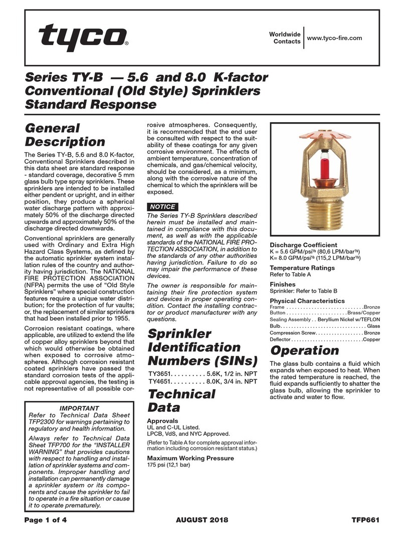
Toro R Series Guide

Introduction
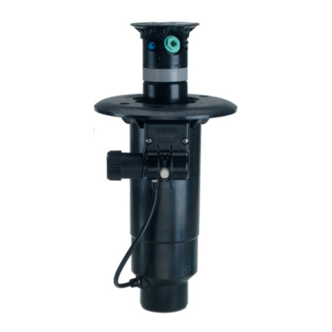
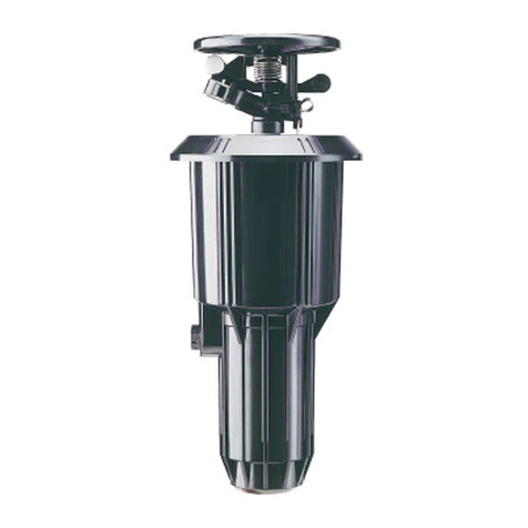
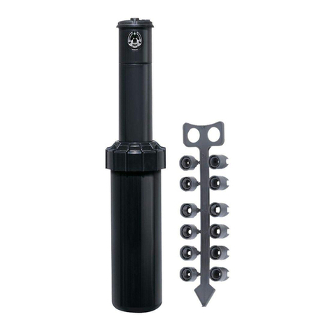
The Toro R Series sprinkler conversion assemblies provide a convenient,
cost-effective method of upgrading existing Rain Bird® Eagle™ 900 and
1100 Series sprinklers to industry-leading Toro irrigation technology.
Benefits include:
• Simple, flexible TruJectory™ spray height adjustment
• 1” (38mm) increase in pop-up height
• Adjustable 40°–330° part-circle and true 360° full circle rotation
in one sprinkler (855RB/DT55RB series)
• Ratcheting riser and arc adjustment band for easy, accurate watering
pattern definition.
Installation Procedure
WARNING: Prior to performing any service procedure on a large-turf irrigation system, ensure the controller
and water supply are shut off and secured to prevent inadvertent operation. When manually operating the
sprinkler pilot valve, never stand or lean over the top of the sprinkler. When performing arc/spray adjustment
procedures during operation, never come in full contact with spray. Failure to comply can result in serious injury.
R Series Sprinkler Conversion Assembly
Installation and Adjustment Guide
1. Insert a small screwdriver blade through the slot
provided in the sprinkler assembly retaining ring.
Pry the end of the ring out of the body, then work
the blade around the retainer to remove.
2. Pry the sprinkler assembly up and out of the body.
3. Ensure the conversion assembly is prepared for
installation with the riser hold up tool inserted as
shown in Figure 3.
4. Insert the conversion assembly into the body ensuring
the ratchet ring is properly keyed to the body guides.
Figure 2
Figure 1
Figure 3
Figure 4
Ratchet Ring
Body Guides
Hold Up Tool Slot,
855R Series
Retaining Ring
Riser Hold Up
Support Tool
Hold Up Tool Slot,
DT55/54R Series
Seal Retainer
Toro 855 R Series
Conversion Assembly
installed in Rain Bird
Eagle 900 body

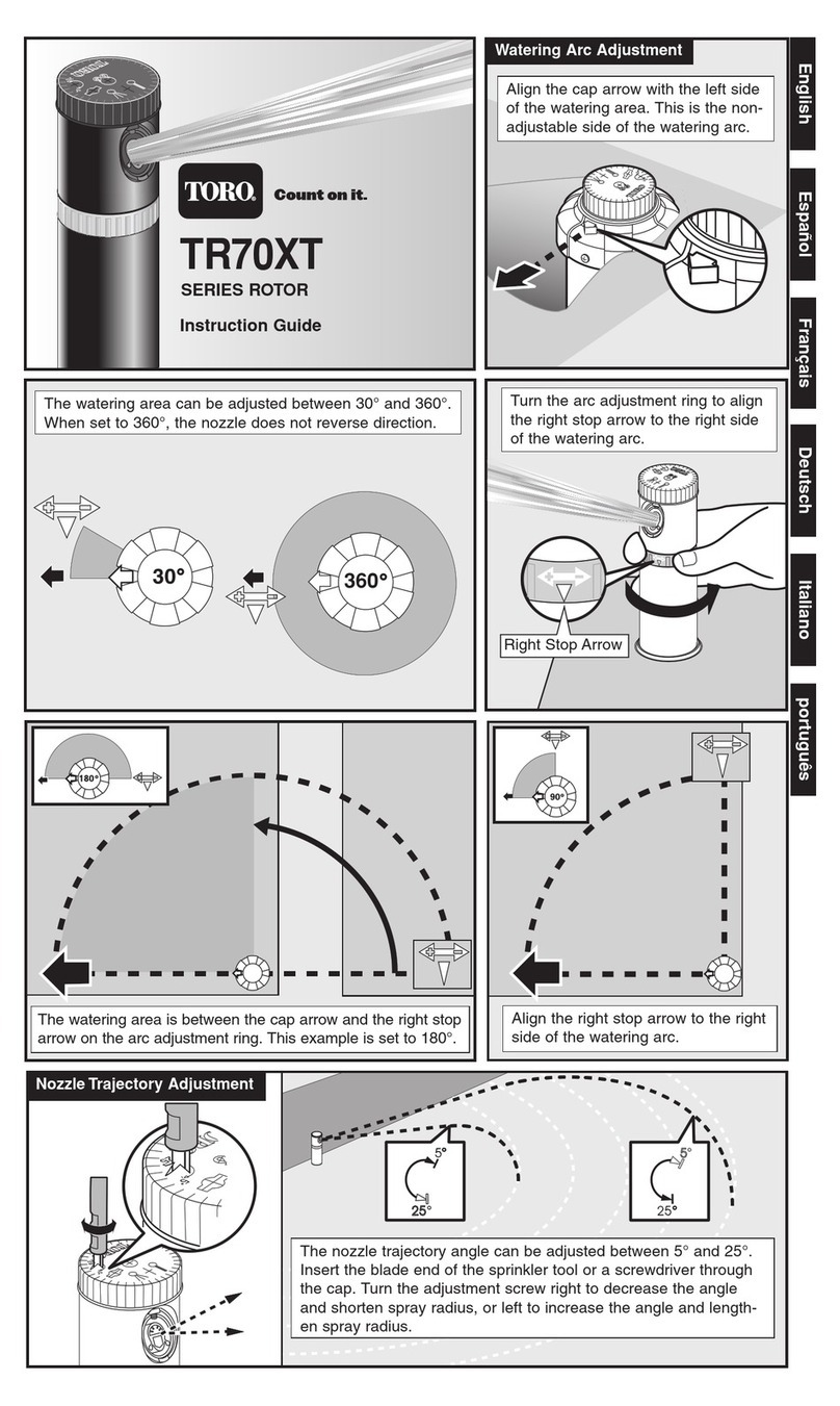
855RB and DT55RB Series Arc Pattern Adjustment
The left side of the sprinkler’s part-circle arc pattern is non-adjustable, requiring all arc pattern adjustments to be
made on the right side of the pattern. Adaptive arc adjustment enables the pattern to be set in 5° increments, ranging
from 40° minimum, to 330° maximum. Standard part-circle arc settings for 1/4, 1/2, 3/4, and continuous full-circle
rotation are indicated on the riser assembly, enabling the watering pattern to be easily set prior to installation.
Note: The 855RB and DT55RB sprinkler conversion assembly arc pattern is factory-set to 180° (1/2 circle).
Adaptive Arc Adjustment – 40° to 330°
1. Insert the end of the Multipurpose Tool (#995-83) into the slot provided in the top of
the cap. Hook the inner edge of the cap to pull the riser assembly up. Grasp the riser
assembly firmly below the arc adjustment band to prevent retraction. See Figure 7.
2. Slowly rotate the nozzle turret back and forth to locate the current left and right
travel limits. Leave the nozzle turret rotated to the left travel limit. See Figure 8.
3. Align the nozzle turret with the left watering border by rotating the ratcheting riser
assembly in either direction. See Figure 9.
Caution: Never attempt to turn the ratcheting riser assembly during operation.
Forcing the riser assembly to turn can result in severe sprinkler damage.
4. Rotate the nozzle turret clockwise to the right travel limit. See Figure 10.
5. Squeeze and hold the arc adjust band at the ribbed section. Rotate the nozzle turret
in either direction to the desired right limit, then release pressure on adjustment band.
See Figure 11.
6. Slowly rotate the nozzle turret back and forth to check the adjusted arc pattern.
7. Check the arc pattern again during sprinkler operation. Fine tune the arc as needed
to achieve the optimum watering pattern.
Figure 7
Figure 8 Figure 9 Figure 10 Figure 11
Turn to Left
Travel Limit Turn Riser to
Align with
Left Border
Turn to Right
Travel Limit
Squeeze Arc
Adjust Band
at Ribs
Multipurpose
Tool (#995-83)
5. Press the seal retainer into the body until it bottoms
out – just below the bottom of the snap ring groove.
See Figure 5.
6. Fit the snap ring onto the riser assembly, orienting
the stepped side facing up (as shown in the cross
section in Figure 6).
7. Insert either end of the snap ring into the groove
just above the seal retainer. Continue working the
ring into the groove until it is fully seated and flush
against the seal retainer.
Note: When properly installed, the snap ring end gap
will measure approximately 1/2” (13 mm).
Figure 6Figure 5
Snap Ring
Arc Adjust
Band

Standard Arc and Full Circle Adjustment
The arc adjustment band is marked for 1/4, 1/2, 3/4
and full-circle settings.
1. Squeeze the ribbed area of the arc adjustment
band (see Figure 11), then rotate the band
to align the desired indicator with the arrow
indicator on the side of the nozzle turret (directly
below the back nozzle). See Figure 12.
Main Nozzle Trajectory Adjustment
Main nozzle spray trajectory can be easily adjusted
up or down to help compensate for difficult watering
conditions, such as mounded turf or low overhead
obstructions.
The default trajectory setting is 25°. The 855RB
sprinkler series has an adjustment range of 7° to 30°,
and is accessed through the top of the cap, either
wet or dry. The DT55/54RB series sprinklers provide a
15° or 25° trajectory angle, and are adjusted dry with
the sprinkler cap removed.
Note: Spray radius will decrease proportionally when
decreasing the trajectory angle.
For DT55/54RB series: A #2 Phillips screwdriver and
a 5/8” nut driver (p/n 995-83) are required for this
procedure.
1. Remove the cap screw and cap.
2. Rotate the main nozzle assembly clockwise to
orient the indicator tab to the 15° or 25° trajectory
position as shown in Figure 13.
3. Reinstall the cap.
For 855RB series: A 5/16” nut driver (p/n 995-105) is
required for this procedure .
1. Turn the trajectory adjustor left to increase, or
right to decrease angle. See Figure 13.
Main Nozzle Diffusion Adjustment (optional)
A 3/32” hex driver (P/N 995-82) is required for this
procedure.
1. Move the diffusion screw from its storage position
next to the cap screw, to the pilot hole in front of
the main nozzle.
2. With the sprinkler operating, adjust the screw
depth for the preferred amount of spray diffusion.
Caution: The diffusion screw can be lost in the nozzle
stream if over-adjusted.
Cap Marker Installation
The lavender-color cap insert (provided), or optional
yardage markers are easily installed in place of the blank
insert. A small slotted screwdriver and diagonal cutters
are required for this procedure.
1. Insert the screwdriver tip under the inside edge of
the blank cap and pry upward to remove..
2. Press the inserts into place, flush with the cap.
3. Trim off the two outer insert tabs, flush with the
bottom of the cap.
Figure 12
25°
30°
Figure 13
855RB
1/4
3/4
1/2
Full
15°
7°
855RB
Figure 14
Figure 15
855RB Series
855RB Series
DT54/55RB
Diffusion
Screw
3/32” Hex Driver
(#995-82)
Relocate
Diffusion
Screw
Trim Outer
Tabs Flush
DT54/55RB

Front Nozzle Performance Charts
Back Nozzle Performance Charts
855RB-5154 Performance Chart 855RB-5558 Performance Chart
Front
Nozzle
Positions
Nozzle Set 51
(Yellow)
Nozzle Set 52
(Blue)
Nozzle Set 53
(Brown)
Nozzle Set 54
(Orange)
Nozzle Set 55
(Green)
Nozzle Set 56
(Gray)
Nozzle Set 57
(Black)
Nozzle Set 58
(Red)
102-4587 102-4588 102-4589 102-0728 102-0729 102-0730 102-4261 102-4260
Blue Gray Red Gray Orange Gray Orange Gray Blue Gray Blue Gray Orange Gray Blue Gray
102-2925 102-2910 102-2928 102-2910 102-2926 102-2910 102-2926 102-2910 102-2925 102-2910 102-2925 102-2910 102-2926 102-2910 102-2925 102-2910
Back
Nozzle
Positions
Red Plug Red Plug Red Plug Red Plug Red Plug Red Plug Red Plug Red Plug
102-4335 102-4335 102-4335 102-4335 102-4335 102-4335 102-4335 102-4335
PSI rad/ft gpm rad/ft gpm rad/ft gpm rad/ft gpm rad/ft gpm rad/ft gpm rad/ft gpm rad/ft gpm
60 55 16.1 63 20.3 69 23.4 75 31.3 — — — — — — — —
70 56 17.4 66 21.8 70 25.3 76 33.8 — — — — — — — —
80 57 18.5 68 23.3 72 27.0 77 36.0 80 39.1 85 41.0 88 45.4 92 49.7
90 58 19.4 70 24.5 75 28.5 79 38.1 83 41.5 87 43.5 91 48.2 94 52.8
100 59 20.5 72 25.9 76 30.0 80 40.2 86 43.7 90 45.7 94 50.6 96 55.3
Stator 102-1939 Yellow 102-1940 White
Conver. 855RB-5154 855RB-5558
DT54RB-5154 Performance ChartDT54RB-5558 Performance Chart
Front
Nozzle
Positions
Nozzle Set 51
(Yellow)
Nozzle Set 52
(Blue)
Nozzle Set 53
(Brown)
Nozzle Set 54
(Orange)
Nozzle Set 55
(Green)
Nozzle Set 56
(Gray)
Nozzle Set 57
(Black)
Nozzle Set 58
(Red)
102-0725 102-7001 102-0727 102-7002 102-6908 102-0730 102-4261 102-4260
Red Plug Red Plug Red Plug Red Plug Red Plug Red Plug Red Plug Red Plug Red Plug Red Plug Red Plug Red Plug Red Plug Brown Red Plug Brown
102-4335 102-4335 102-4335 102-4335 102-4335 102-4335 102-4335 102-4335 102-4335 102-4335 102-4335 102-4335 102-4335 102-6883 102-4335 102-6883
Back
Nozzle
Positions
Yellow Blue Yellow Orange Yellow Red Yellow Beige Yellow Beige Yellow Red Yellow Gray Yellow Gray
102-6937 102-2925 102-6937 102-2926 102-6937 102-2928 102-6937 102-2929 102-6937 102-2929 102-6937 102-2928 102-6937 102-4965 102-6937 102-4965
PSI rad/ft gpm rad/ft gpm rad/ft gpm rad/ft gpm rad/ft gpm rad/ft gpm rad/ft gpm rad/ft gpm
60 59 14.6 62 17.4 68 24.3 71 28.2 — — — — — — — —
70 60 15.7 63 18.8 70 26.3 75 30.6 — — — — — — — —
80 61 16.4 64 20.0 72 27.6 78 32.6 83 39.5 85 42.7 87 45.9 91 50.2
90 62 17.8 66 21.3 74 29.9 80 34.7 85 41.6 88 44.9 90 48.5 93 52.8
100 63 18.1 67 23.6 75 30.4 81 36.7 87 43.7 90 46.8 93 51.2 95 55.4
Stator 102-6929 Blue 102-1940 White
Conver. DT54RB-5154 DT54RB-5558
Not recommended at these pressures. Radius shown in feet.
Toro recommends the use of a 11⁄4" swing joint at flows over 25-GPM (95-LPM). Sprinkler radius data collected in Toro’s zero wind test facility per ASAE standard S398.1.
Actual site conditions must be considered when selecting the appropriate nozzle.
DT55RB-5154 Performance ChartDT55RB-5558 Performance Chart
Front
Nozzle
Positions
Nozzle Set 51
(Yellow)
Nozzle Set 52
(Blue)
Nozzle Set 53
(Brown)
Nozzle Set 54
(Orange)
Nozzle Set 55
(Green)
Nozzle Set 56
(Gray)
5Nozzle Set 57
(Black)
Nozzle Set 58
(Red)
102-6906 102-0726 102-6907 102-0728 102-6955 102-6935 102-6936 102-6909
Yellow Brown Yellow Yellow Yellow Yellow Yellow Yellow Yellow Green Green Green Green Green Green Green
102-5670 102-5671 102-5670 102-6884 102-5670 102-6884 102-5670 102-6884 102-5670 102-6885 102-6531 102-6885 102-6531 102-6885 102-6531 102-6885
Back
Nozzle
Positions
Red Plug Red Plug Red Plug Red Plug Red Plug Red Plug Red Plug Red Plug Red Plug Red Plug Red Plug Red Plug Red Plug Red Plug Red Plug Red Plug
102-4335 102-4335 102-4335 102-4335 102-4335 102-4335 102-4335 102-4335 102-4335 102-4335 102-4335 102-4335 102-4335 102-4335 102-4335 102-4335
PSI rad/ft gpm rad/ft gpm rad/ft gpm rad/ft gpm rad/ft gpm rad/ft gpm rad/ft gpm rad/ft gpm
60 56 15.2 57 20.1 66 24.3 68 28.0 — — — — — — — —
70 58 16.5 60 21.7 67 26.2 71 30.4 — — — — — — — —
80 59 17.5 62 23.1 68 27.8 72 31.7 76 39.7 80 43.1 83 48.2 85 53.0
90 60 18.4 64 24.5 71 28.8 74 34.5 78 43.1 81 45.1 86 51.2 87 56.0
100 61 19.3 66 25.3 72 30.3 75 36.5 80 45.5 82 49.0 90 54.5 89 59.0
Stator 102-1939 Yellow 102-1940 White
Conver. DT55RB-5154 DT55RB-5558
Nozzles 65 PSI 80 PSI
Part # Description Color Radius GPM Radius GPM Profile
Nozzles 65 PSI 80 PSI
Part # Description Color Radius GPM Radius GPM Profile
102-6937 Inner Nozzle
w/ Yellow Restrictor Yel/Yel 29 3.7 30 4.1
102-6531 Inner Nozzle
w/ White Restrictor Grn/Wht 31 4.3 33 4.6
102-6883 Intermediate Nozzle Brown 38 2.8 38 2.8
102-6884 Intermediate Nozzle Yellow 41 4.1 43 4.5
102-6885 Intermediate Nozzle Green 42 5.4 45 6.0
102-2925 Intermediate Nozzle Blue 40 2.8 42 3.2
102-2926 Intermediate Nozzle Orange 44 4.3 45 4.8
102-2927 Intermediate Nozzle Gray 46 5.1 47 5.4
102-2928 Intermediate Nozzle Red 48 6.5 50 7.0
102-2929 Intermediate Nozzle Beige 51 8.1 53 9.1
© 2011 The Toro Company • Irrigation Division • www.toro.com Form Number 373-0581 Rev. A
This manual suits for next models
6
Other Toro Irrigation System manuals

Toro
Toro MULTIMATIX 720G User manual

Toro
Toro 69X-01-XX Quick guide

Toro
Toro SingleStream 53261 User manual

Toro
Toro T5 Series User manual

Toro
Toro 340 Series User manual

Toro
Toro 860S Series Quick guide

Toro
Toro P2 Series User manual

Toro
Toro FLX35 Series Quick guide

Toro
Toro IMPACT 53721 User manual

Toro
Toro 2001 Series User manual

Toro
Toro INFINITY Series User manual

Toro
Toro TR50XT Series Manual

Toro
Toro 340 Series User manual

Toro
Toro Super 800 Series User manual

Toro
Toro 53763 User manual

Toro
Toro 640 Series Quick guide

Toro
Toro TR50 Series Manual

Toro
Toro TS120 User manual

Toro
Toro TR50XT Series Manual

Toro
Toro TruJectory FLEX800 Series User manual