2
Note: Seal will be destroyed when servicing the rear roller.
Do not attempt to re-use these seals.
Bearing Removal
Reference: The bearings are pressed on to the shaft
(.0003–.0016 in. interference) and loose fit to housing
(.0020–.0035 in. clearance).
1. Remove retaining ring (Fig. 3). Repeat on other end.
2. Loosely secure roller assembly in bench vise and lightly
tap one end of roller shaft until free from housing.
3. Remove second bearing from shaft. Support bearing on
inner race and tap on roller shaft.
4. Inspect bearings, shaft, and retaining ring for damage.
Replace damaged components. Re-assemble roller.
Assembly
1. Press bearing onto one end of shaft. Apply pressure to
inner race only.
2. Install spiral retaining ring on same end as assembled
bearing.
3. Install shaft with single bearing into tube assembly.
4. Install second bearing into roller assembly. Press only
on inner race. The inner race will contact shoulder of
shaft before outer race contacts shoulder of housing.
5. Install second spiral retaining ring.
6. Partially fill cavity between bearing and seal with
grease, prior to installation of new seals, to prevent
contamination.
7. Press new seal flush to .030 in. recessed into housing.
Repeat for other side.
Front Roller
Inspect front roller for wear, excess wobble or binding.
Service or replace roller or components if any of these
conditions exist.
Disassembly
1. Remove roller mounting bolt (Fig. 4).
2. Insert punch through end of roller housing and drive
opposite bearing out by alternating taps to opposite side
of inner bearing race. There should be a 1/16 in.
(.060 in.) lip of inner race exposed.
1
2
3
4
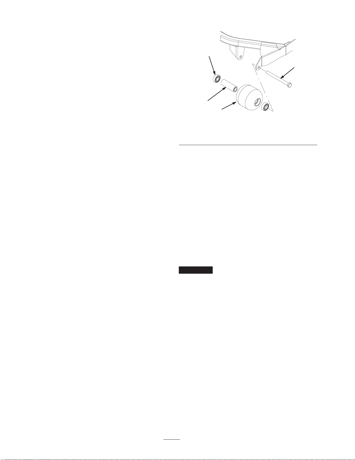
Figure 4
1. Front roller
2. Mounting bolt 3. Bearing
4. Bearing spacer
3. Push second bearing out in press.
4. Inspect roller housing, bearings, and bearing spacer for
damage (Fig. 4). Replace damaged components and
re-assemble.
Assembly
1. Press first bearing into roller housing (Fig. 4). Press on
outer race only or equally on inner and outer race.
2. Insert spacer (Fig. 4).
3. Press second bearing into roller housing (Fig. 4)
pressing equally on inner and outer race until the inner
race comes in contact with spacer.
4. Install roller assembly into deck frame.
Important Securing roller assembly with a gap larger
than .060 in. creates a side load on bearing and can lead to
premature bearing failure.
5. Verify that there is no more than a .060 in. gap between
roller assembly and the roller mount brackets of the
deck frame. If there is a gap over .060 in., install
enough 5/8 in. diameter washers to take up the slop.
6. Secure mounting bolt to 80 ft.-lb. (108 N⋅m).


