manuals.online logo
Brands
  1. Home
  2. •
  3. Brands
  4. •
  5. Toro
  6. •
  7. Lawn Mower Accessories
  8. •
  9. Toro 78537 User manual

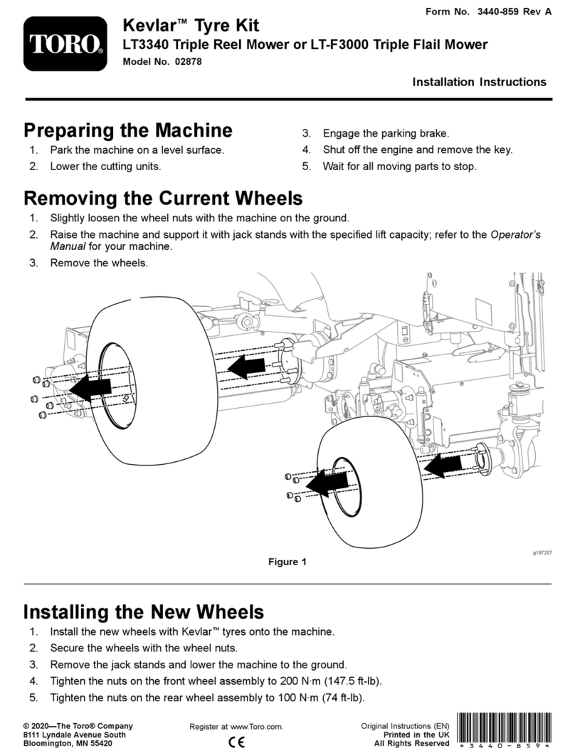
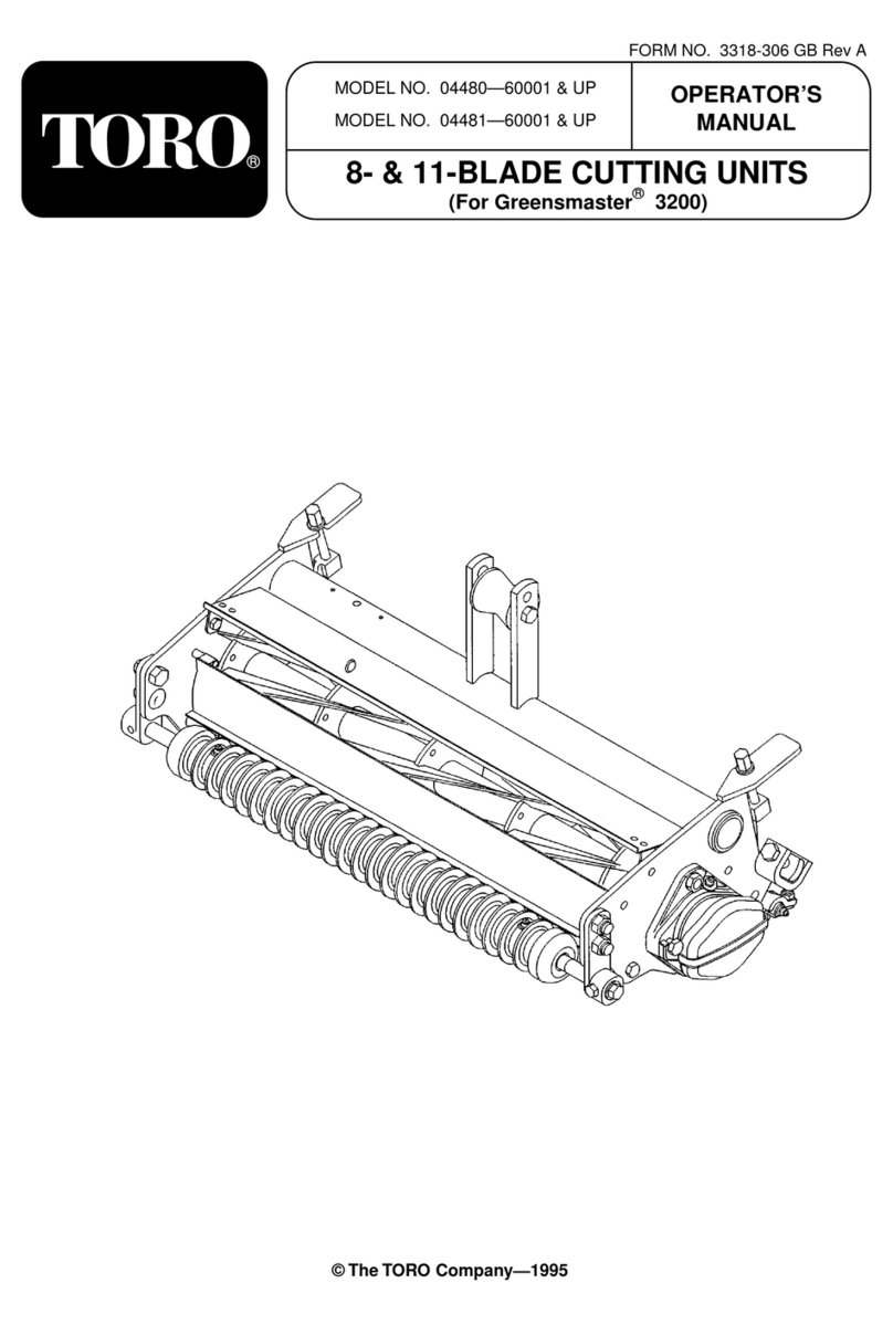
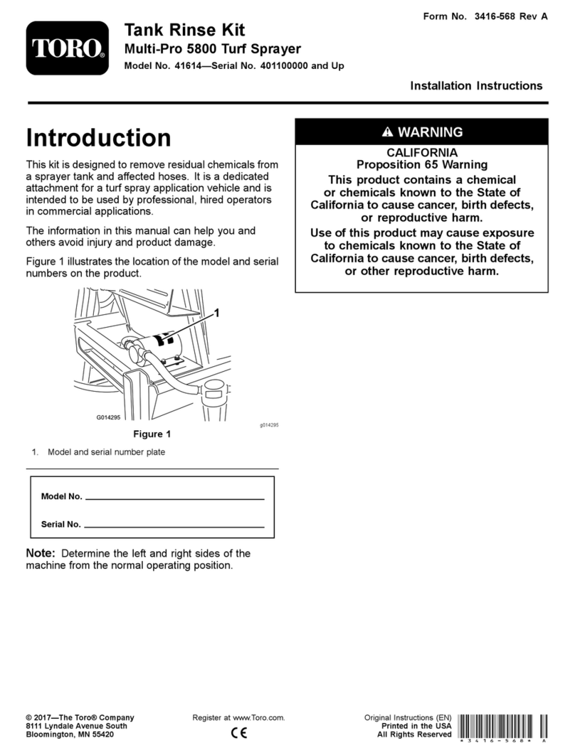
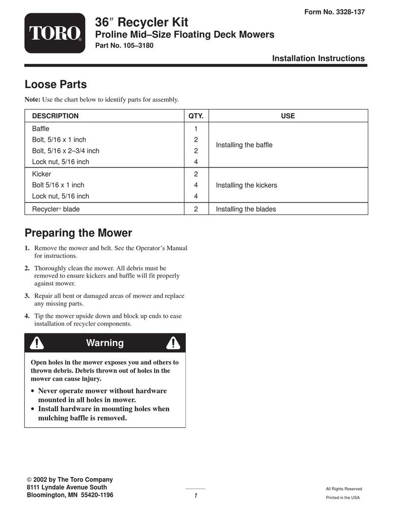
Toro 78537 User manual

Other Toro Lawn Mower Accessories manuals

Toro Polar Trac Cab 30474 User manual

Toro

Toro Polar Trac Cab 30474 User manual

Toro 30215 User manual

Toro

Toro 30215 User manual

Toro GrandStand 133-1495 User manual

Toro

Toro GrandStand 133-1495 User manual

Toro 138-0798 User manual

Toro

Toro 138-0798 User manual

Toro HoverPro 450 User manual

Toro

Toro HoverPro 450 User manual

Toro Z Master 116-0231 User manual

Toro

Toro Z Master 116-0231 User manual

Toro TITAN ZX Series User manual

Toro

Toro TITAN ZX Series User manual

Toro Z Master 74060 Quick start guide

Toro

Toro Z Master 74060 Quick start guide

Toro 22441 User manual

Toro

Toro 22441 User manual

Toro 140-9347 User manual

Toro

Toro 140-9347 User manual

Toro 04707 User manual

Toro

Toro 04707 User manual

Toro Workman GTX Series User manual

Toro

Toro Workman GTX Series User manual

Toro Greensmaster TriFlex 3300 Series User manual

Toro

Toro Greensmaster TriFlex 3300 Series User manual

Toro REELMASTER 6000 Series User manual

Toro

Toro REELMASTER 6000 Series User manual

Toro 147-0520 User manual

Toro

Toro 147-0520 User manual

Toro 140-2054 User manual

Toro

Toro 140-2054 User manual

Toro 145-8319 User manual

Toro

Toro 145-8319 User manual

Toro 31213 User manual

Toro

Toro 31213 User manual

Toro 78534 User manual

Toro

Toro 78534 User manual

Toro 22202 User manual

Toro

Toro 22202 User manual

Toro 78593 User manual

Toro

Toro 78593 User manual

Toro 78463 User manual

Toro

Toro 78463 User manual

Toro 133-0157 User manual

Toro

Toro 133-0157 User manual

Toro Groundsmaster 360 Series User manual

Toro

Toro Groundsmaster 360 Series User manual

Popular Lawn Mower Accessories manuals by other brands

Ariens 891008 Operator's manual

Ariens

Ariens 891008 Operator's manual

Rover 108 - 109 owner's manual

Rover

Rover 108 - 109 owner's manual

Snapper 1690047 Operator's manual

Snapper

Snapper 1690047 Operator's manual

RHINO 800 Operator's manual

RHINO

RHINO 800 Operator's manual

Exmark Quest 126-7506 Operator's manual

Exmark

Exmark Quest 126-7506 Operator's manual

Snapper 1685167 installation instructions

Snapper

Snapper 1685167 installation instructions

Cub Cadet 19B70029100 installation manual

Cub Cadet

Cub Cadet 19B70029100 installation manual

Stihl AMK 043.1 instruction manual

Stihl

Stihl AMK 043.1 instruction manual

MTD 753-0873 Service kit manual

MTD

MTD 753-0873 Service kit manual

Bush Hog RG60 Operator's manual

Bush Hog

Bush Hog RG60 Operator's manual

Scag Power Equipment GC-F4 Operator's manual

Scag Power Equipment

Scag Power Equipment GC-F4 Operator's manual

Land Pride RCF2760 Operator's manual

Land Pride

Land Pride RCF2760 Operator's manual

Peco SPARTAN RZ Series Operator's manual

Peco

Peco SPARTAN RZ Series Operator's manual

Peco 28621206 Operator's manual

Peco

Peco 28621206 Operator's manual

Simplicity 367 Operator's manual

Simplicity

Simplicity 367 Operator's manual

Simplicity 211 Operator's manual

Simplicity

Simplicity 211 Operator's manual

Iseki SSM72 Operators & service manual

Iseki

Iseki SSM72 Operators & service manual

Simplicity 1690043 Operator's manual

Simplicity

Simplicity 1690043 Operator's manual

manuals.online logo
manuals.online logoBrands
  • About & Mission
  • Contact us
  • Privacy Policy
  • Terms and Conditions

Copyright 2025 Manuals.Online. All Rights Reserved.

Form No. 3355-379 Rev B
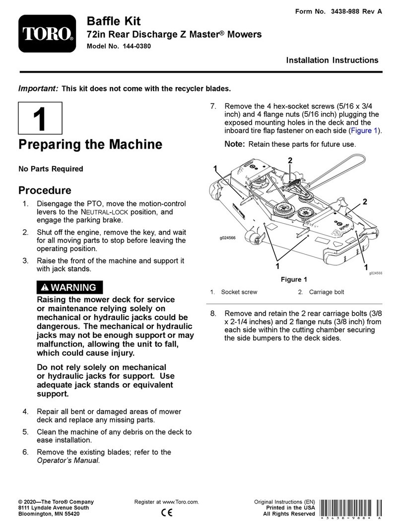
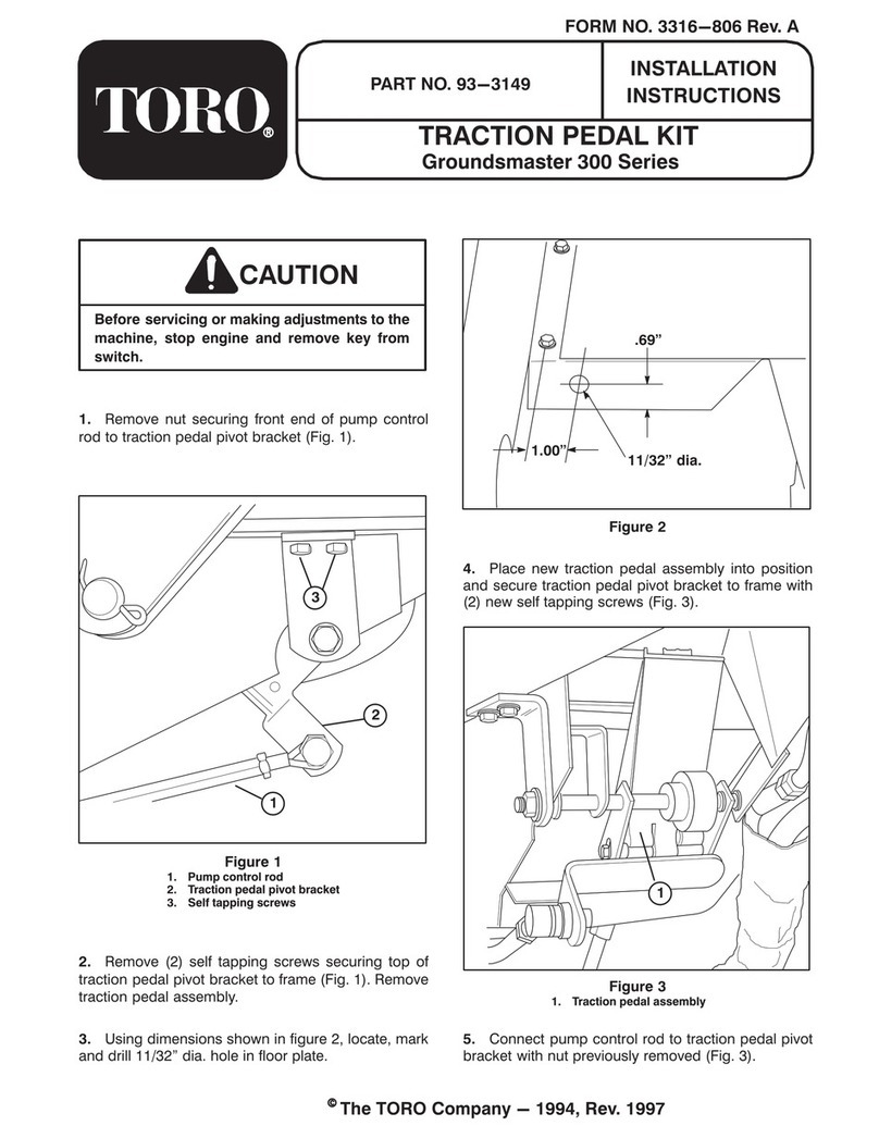
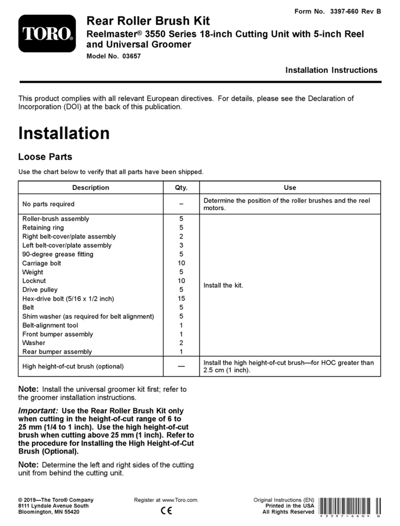
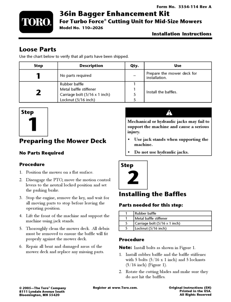
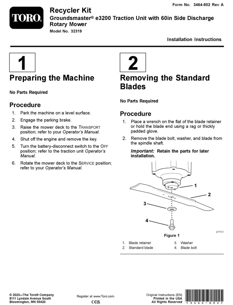
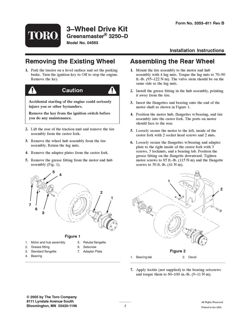
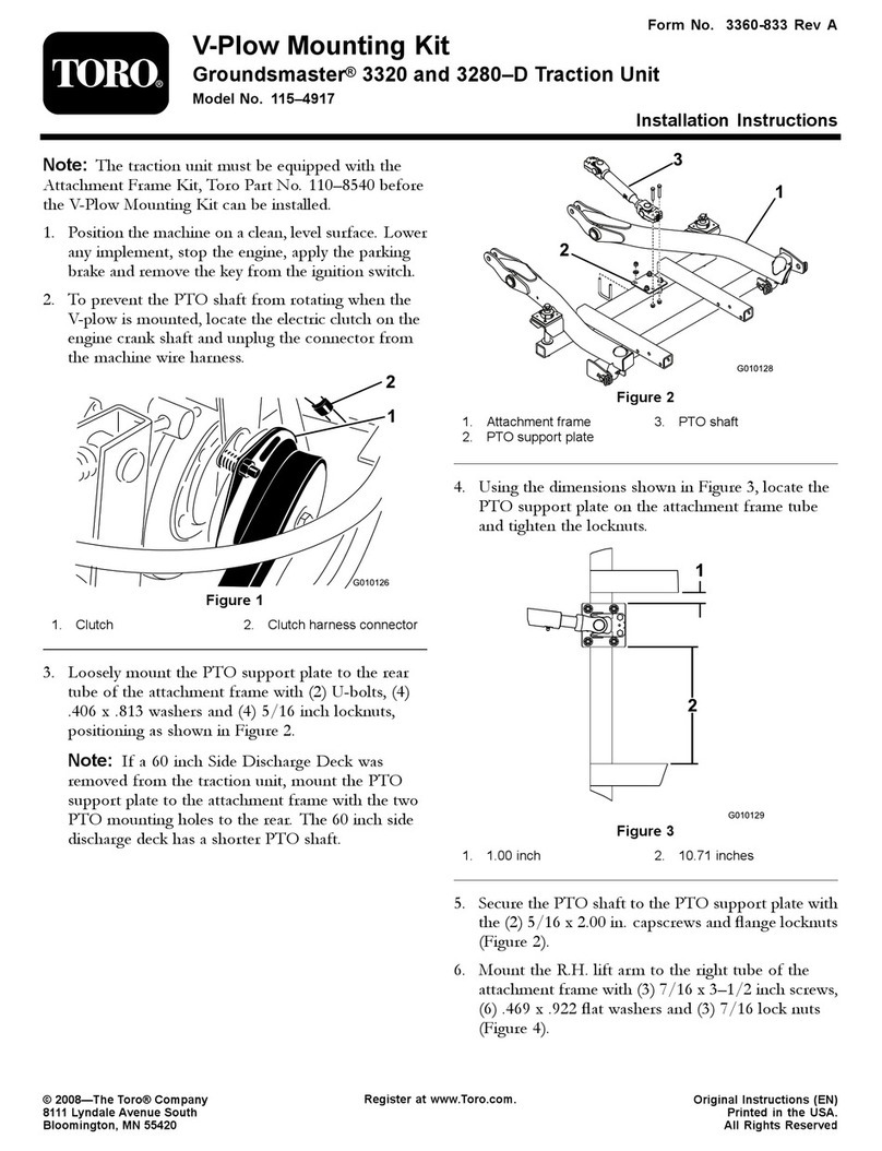
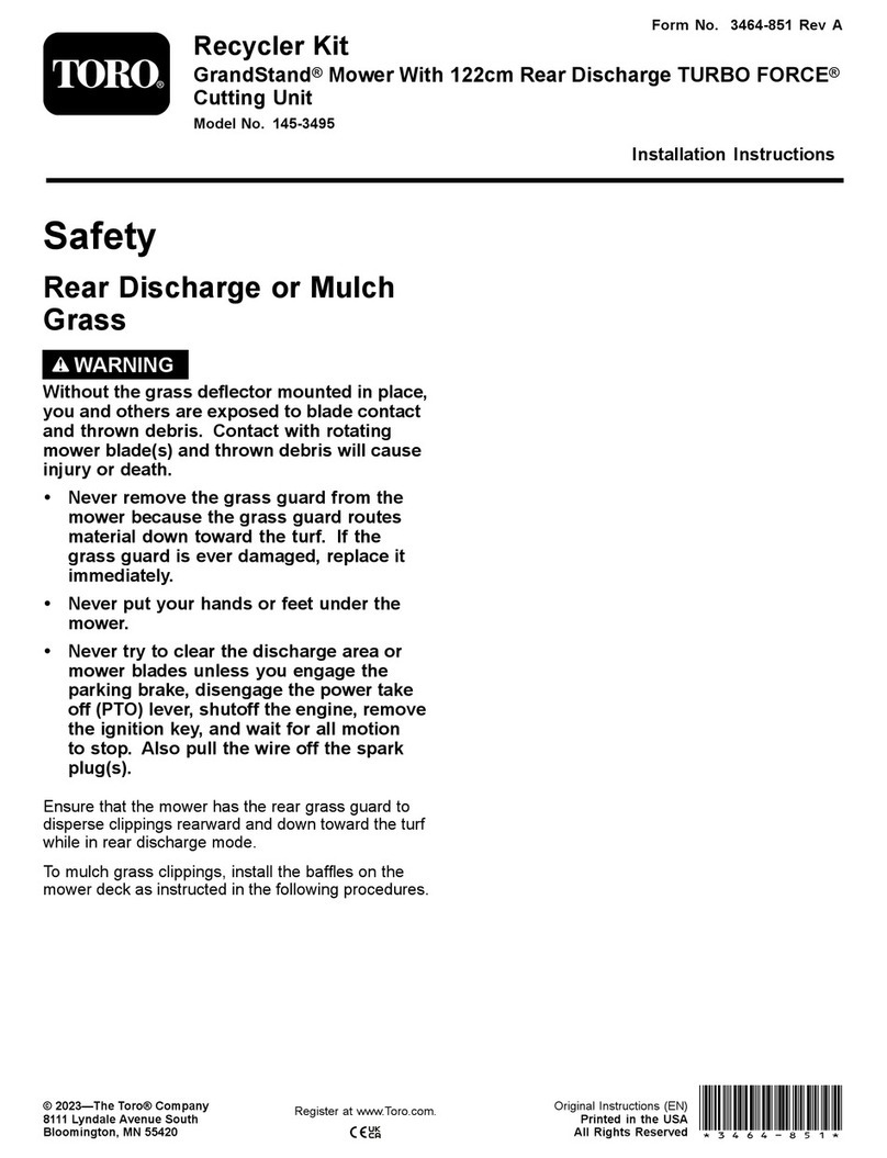
Blower and Drive KitFor 52in E-Z Vac® Bagger for Z400 and Z500 Series ZMaster® MowersModel No. 78537 —Serial No. 260000001 and Up
Installation Instructions
Note: Deter mine the left and right sides of the mac hine from the nor mal operating position.
Loose PartsUse the chart below to verify that all parts have been shipped.
Step
Description
Qty.
Use
1
No parts required
–
Verify an existing pivot tube.
2
No parts required
–
Prepare the mower and remove thebelt cover.
3
No parts required
–
Remove the existing anti-scalproller and bracket.
4
Pulley assembly
1
Install the pulley assembly.
Pivot bracket
1
Metal template
1
Bolt (3/8 x 1 inch)
35
Locknut (3/8 inch)
3
Install the pivot bracket.
Blower assembly
1
Bagger belt
16
Blower belt cover
1
Install the blower, bagger belt,spring, and belt cover.
Step
1
Verifying an Existing PivotTube
No Parts Required
Procedure
If y our mo w er has a pi v ot tube as sho wn in Figure
1 , then proceed to Ste p 6 and the Operator’ s
Man ual to install the blo w er assembly .
Note: Do not remo v e the existing pi v ot tube .
Figure 1
1. Z400 mower deck 3. Z500 mower deck2. Pivot tube 4. Pivot tube
© 2006—The Toro® Company8111 Lyndale Avenue SouthBloomington, MN 55420
Register at www.Toro.com. Original Instructions (EN)Printed in the USA.All Rights Reserved
Step
2
Preparing the Mower andRemove the Belt Cover
No Parts Required
Procedure
P erfor m the follo wing procedure to pre pare the
mo w er for attac hing the blo w er and finishing kit.
1. Diseng ag e the PTO , mo v e the motion control
lev ers to the neutral loc k ed position and set
the parking brak e .
2. Stop the engine , remo v e the k ey , and w ait for
all mo ving par ts to stop before lea ving the
operating position.
3. R e pair all bent or damag ed areas of mo w er
dec k and re place any missing par ts .
4. Clean the mo w er of any debris on the dec k or
rear par t of the mo w er to ease installation.
Note: Clean the area around the belt co v er
before remo ving .
5. Unlatc h and remo v e the right belt co v er . Sa v e
this hardw are .
6. Store the right belt co v er for later use . If the
bag g er blo w er and pulley is remo v ed it can be
reused.
Step
3
Removing the ExistingAnti-Scalp Roller andBracket
No Parts Required
Procedure
Note: Clean the area around the right, rear
anti-scalp wheel.
1. R emo v e the anti-scalp roller from the brac k et
b y loosening and remo ving the flang e n ut (3/8
inc h) and axle bolt (3/8 x 4-1/2 inc h) as sho wn
in Figure 2 .
2. R emo v e the three car riag e bolts (3/8 x 3/4
inc h) and flang e n uts (3/8 inc h) securing the
brac k et to the mo w er ( Figure 2 ). Sa v e the
fasteners for later use .
3. R emo v e the brac k et and discard.
Figure 2
1. Anti-scalp roller
4. Carriage bolt, (3/8 x 3/4inch)2. Anti-scalp bracket
5. Flange nut, (3/8 inch)3. Bolt, (3/8 x 4–1/2 inch)
6. Mower deck
Step
4
Installing the PulleyAssembly
Parts needed for this step:
1
Pulley assembly
Procedure
1. Lo w er the mo w er dec k to the lo w est
height-of-cut position.
2
2. Loosen, but do not remo v e , the tapping bolts
on the existing mo w er dec k pulley ( Figure 3 ).
T here should be a 3/16 inc h (5 mm) clearance
betw een the bolt head and pulley .
3. Align the new pulley assembly so that the
openings fit o v er the pulley bolt heads ( Figure
3 ).
4. T ur n the pulley to loc k it into position ( Figure
3 ).
Note: If the pulley does not tur n, loosen
the bolts to raise the bolt heads and allo w the
pulley to loc k into position.
5. After the new pulley assembly is in position,
tighten the existing bolts to secure new pulley
assembly .
Note: T or que the bolts to 23 ft-lb ± 2 ft-lb
(31 N ⋅m ± 3 N ⋅m).
Figure 3
1. Pulley assembly 4. Bolt heads2. Mower deck pulley
5. 3/16 inch (5mm)3. Locking slots
6. R emo v e the belt co v er suppor t brac k et from
the mo w er dec k ( Figure 4 ).
Figure 4
1. Bolt 3. Mower deck2. Belt cover support bracket
Step
5
Installing the Pivot Bracket
Parts needed for this step:
1
Pivot bracket
1
Metal template
3
Bolt (3/8 x 1 inch)
3
Locknut (3/8 inch)
Procedure
1. Install the metal template , with the n umber 52
in it, to the mo w er dec k with the previously
remo v ed car riag e bolts and n uts using the
existing holes in the mo w er dec k ( Figure 5 ).
Mak e sure the car riag e bolts and n uts are tight
and the template is tight ag ainst the mo w er
dec k.
2. Center punc h the new mo w er dec k hole
locations using the 3 holes in the template
( Figure 5 ).
3. R emo v e the metal template and drill three , 1/8
inc h diameter , pilot holes with a shar p drill bit
( Figure 5 ).
3
4. Drill three , 13/32 inc h diameter , holes into the
pilot holes with a shar p drill bit ( Figure 5 ).
5. R emo v e par t of the metal belt co v er suppor t
on top of the mo w er . R efer to Figure 5 for the
cor rect size and location to remo v e .
Figure 5
1. Cut 1 inch (25 mm) off themetal belt cover supporthere
5. Template location onmower deck
2. Mower deck 6. Carriage bolts3. Drill three, 1/8 inch pilotholes and 13/32 inchdiameter holes, here
7. Lock nuts
4. Template with the number52 in it
6. Install the new blo w er pi v ot assembly using
the 3 bolts (3/8 x 1 inc h) and 3 loc kn uts (3/8
inc h) ( Figure 6 ).
7. Install the anti-scalp roller with the axle bolt
(3/8 x 4-1/2 inc hes), flang e n ut (3/8 inc h)
( Figure 6 ).
Figure 6
1. Mower deck
4. Bolt, (3/8 x4–1/2 inch)
7. Bushing
2. Bolt, (3/8 x 1inch)
5. Spacer
8. Blower pivotassembly3. Locknut, (3/8inch)
6. Anti-scalp roller 9. Drilled holes
Step
6
Installing the BlowerAssembly, Bagger Belt,Spring, and Blower BeltCover
Parts needed for this step:
1
Blower assembly
1
Bagger belt
1
Blower belt cover
Procedure
R efer to the bag g er Operator’ s Manual for the
cor rect procedure to install the blo w er , bag g er
belt, spring, and blo w er belt co v er .
4