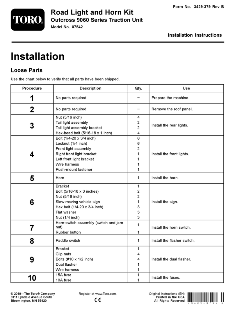
Toro 145-3530 User manual
Other Toro Lawn Mower Accessories manuals
Toro
Toro 133-0157 User manual
Toro
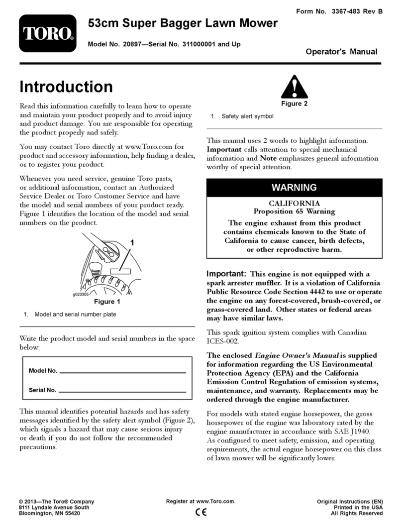
Toro Super Bagger 20897 User manual
Toro
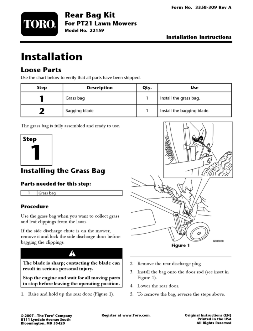
Toro 22159 User manual

Toro
Toro GrandStand 133-1434 User manual
Toro
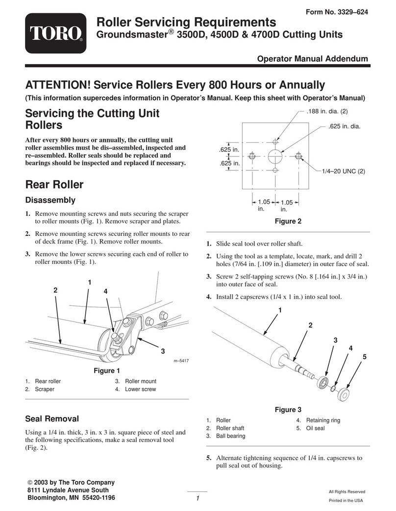
Toro Groundsmaster 3500-D User manual
Toro
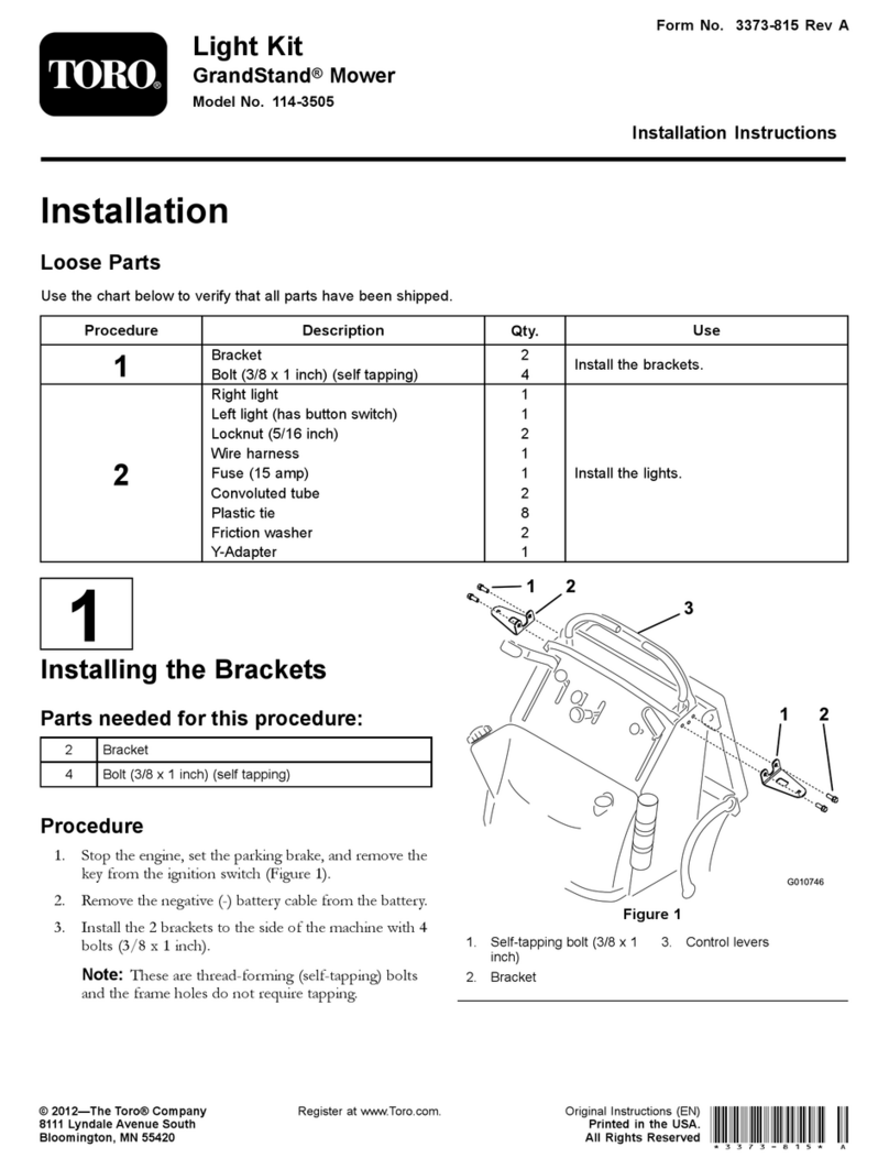
Toro GrandStand 114-3505 User manual
Toro
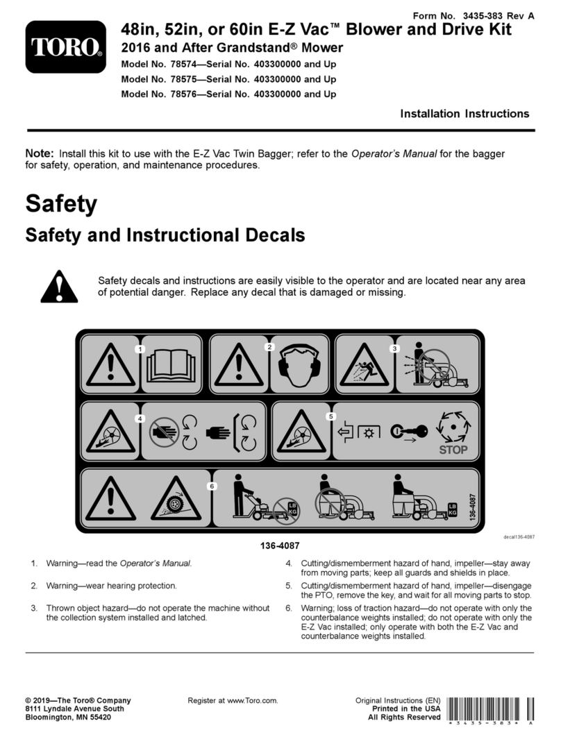
Toro E-Z Vac 78574 User manual
Toro
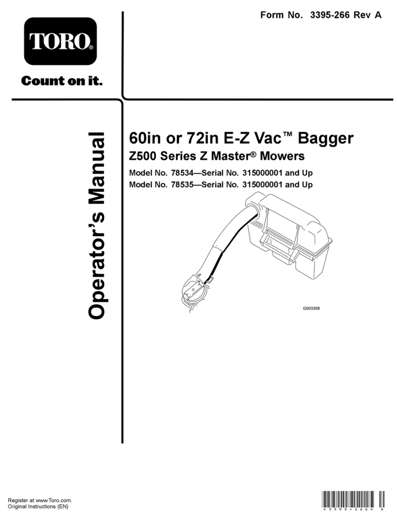
Toro 78534 User manual
Toro
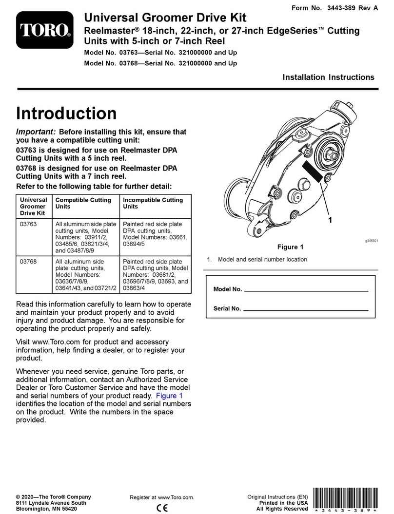
Toro Universal Groomer Drive Kit User manual

Toro
Toro Groundsmaster 4500 Series User manual
Toro
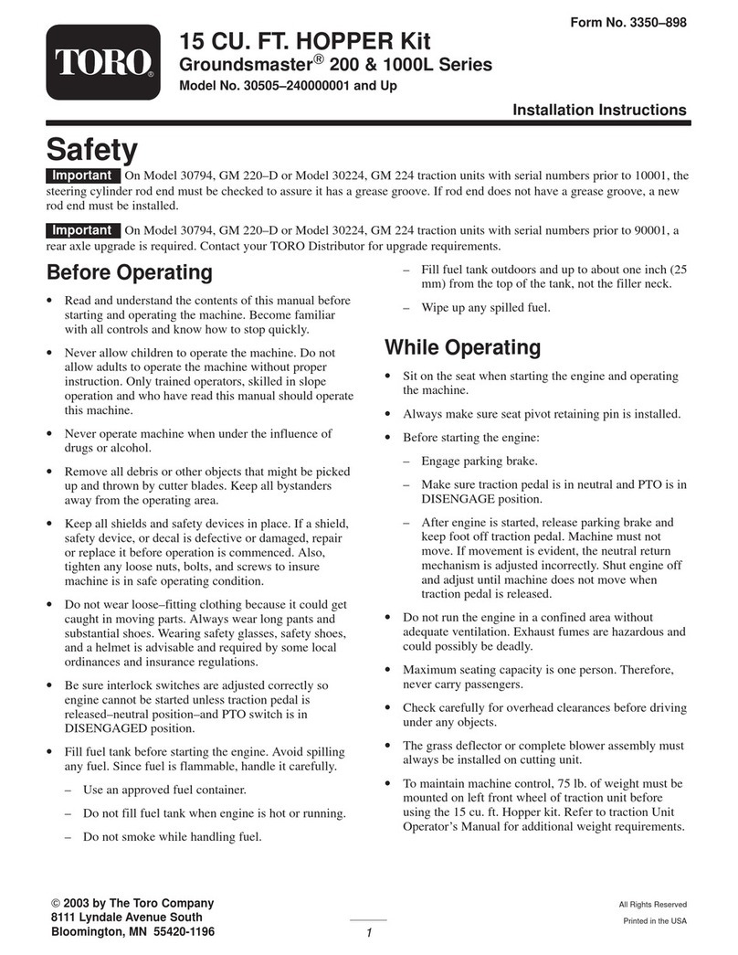
Toro Groundsmaster 200 Series User manual
Toro
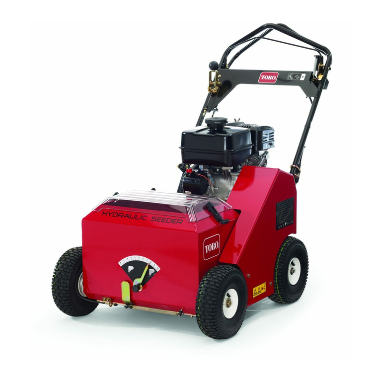
Toro 23508 Installation and operating manual
Toro
Toro 142-7070 User manual

Toro
Toro 59226 User manual

Toro
Toro 03698 User manual
Toro
Toro 44923 User manual
Toro
Toro 04480 User manual

Toro
Toro 138-6246 User manual
Toro
Toro 31204 User manual
Toro
Toro 4045 User manual
